1
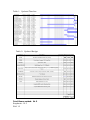
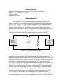
Project Identity
Modified Communication System for Client with Disabilities
Week 11: 11/5/06 – 11/11/06
Philip Licitra
Stephanie Santos
Work Completed
This week, all of our final necessary tasks were completed. We
spent a significant amount making our final assembly of the ABS casing
for the LCD monitor. The pieces were assembled using a cyanoacrylate
bonding agent. Prior to the attachment of the front panel, the monitor
screen was secured to the front panel using several metal clips which
were bolted to the plastic interior. This provided at tight and secure fit for
holding the monitor in place. All of the wire connections were also made.
The final circuit design for the entire monitor is shown in Figure 1:
Figure 1: Power Switch Schematic
The LED will indicate that power is being delivered to the monitor
whether it is connected to the DynaVox or not. All connections to the
power switch were made using secure by removable connectors, so that if
the client ever desires to remove/replace the battery supply, they may do
so without causing any damage to the switch or the rest of the circuit.
The battery was secured by placing small ABS pieces securely around it,
so that it would not slide or shake around the box. Enough room was
allowed for the removal of the battery if so desired. The connector plug
for the VGA cable to the monitor was secured in place inside the box as
well. Once all of the electrical connections were made and all of the
internal components were in place, the front panel was bonded to the
rest of the box. The small PCB containing all the connectors and
switches for the monitor was secured to the removable top panel. The top
panel was then secured to the case with small screws. Once the case was
completely assembled, we spent some time filing and shaping the edges
of the box and rounding off the corners to improve upon the quality of
appearance and the seal at all of the bonding junctions. Figure 2 shows
the interior of the screen enclosure.
Figure 2: Inside View of Screen Enclosure and its Wiring
The top panel was made removable via four screws to allow access
to the battery, interior connections, and the LCD screen brightness,
contrast, and color controls on the PCB that was attached to the top
panel. Figure 3 shows the Tamiya clip for charging the battery and the
screen enclosure mounting bracket on the back panel of the enclosure.
Figure 3: Charging Tamiya Clip on Back Panel
of Screen Enclosure
Future Work
Future work will consist of replacing the four access panel screws
with raised screws, and minor filing of the edges to smooth all corners
and places where two pieces of ABS plastic meet. We will start to
compile the user’s manual and the final report for this project as we have
basically completed its construction and testing. We are also waiting for
some measurements on Franky’s wheelchair to be sure that the joystick
will mount properly.
Now that we have reached our project’s completion, we have made
plans to travel to Sea Girt, NJ on November 26th to make the installation
for our client and to instruct him and his family on how to use the
devices, make all adjustments, and how to install and uninstall the
devices for the client’s own everyday use.
Project Review
As long as all of the information that was received from our client
has been correct, the joystick and screen systems should work properly
with their existing DynaVox system. The joystick and screen can either
be implemented together or work separately as to the liking of our client.
Our timeline is ahead of schedule and we are now under budget due to a
shipment of bonding agent that was never received and thus was
credited to our account. We are $5.16 under our budget of $750.00.
Table 1 shows the updated timeline and Table 2 shows our updated
budget.
Table 1: Updated Timeline
Table 2: Updated Budget
Total Hours worked: 24.5
Stephanie: 12.5
Phil: 12