1
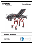
FERNO
®
When It’s Critical ®
Users’ Manual
Model 418-1 Adjustable Lifting Bridle
September, 2010 GLO
Pub. No. 234-0234-04
Read this Manual
and Retain for
Future Reference
Model 418-1 Lifting Bridle
Ferno Technical Support
Disclaimer
Customer service and product support are important aspects of
each Ferno product. For technical support questions:
Telephone (Toll-free)
1.800.733.3766 ext. 1010
Telephone 1.937.382.1451 ext. 1010
This manual contains general instructions for the use, operation
and care of this product. The instructions are not all-inclusive. Safe
and proper use of this product is solely at the discretion of the
user. Safety information is included as a service to the user. All
other safety measures taken by the user should be within and under
consideration of applicable regulations. It is recommended that
training on the proper use of this product be provided before using
this product in an actual situation.
Email
[email protected]
Ferno Customer Relations
Retain this manual for future reference. Include it with the product
in the event of transfer to new users. Additional free copies are
available upon request from Customer Relations.
For ordering assistance or general information:
Canada and the U.S.A.
Telephone (Toll-free)
Telephone Fax (Toll-free)
Fax
1.877.733.0911
1.937.382.1451
1.888.388.1349
1.937.382.1191
Internet
www.ferno.com
All Other Locations
For assistance or information, please contact your Ferno distributor.
If you do not have a Ferno distributor, please contact Ferno
Customer Relations:
Ferno-Washington, Inc.
70 Weil Way
Telephone Fax
Internet
Wilmington, Ohio 45177-9371, U.S.A.
+1.937.382.1451
+1.937.382.6569
Proprietary Notice
The information disclosed in this manual is the property of FernoWashington, Inc., Wilmington, Ohio, USA. Ferno-Washington, Inc.
reserves all patent rights, proprietary design rights, manufacturing
rights, reproduction use rights, and sales use rights thereto, and
to any article disclosed therein except to the extent those rights
are expressly granted to others or where not applicable to vendor
proprietary parts.
Limited Warranty Statement
The products sold by Ferno are covered by a limited warranty,
which is printed on all Ferno invoices. The complete terms and
conditions of the limited warranty, and the limitations of liability
and disclaimers, are also available upon request by calling Ferno at
1.800.733.3766 or 1.937.382.1451.
www.ferno.com
European Representative
Ferno (UK) Limited
Stubs Beck Lane, Cleckheaton
West Yorkshire BD19 4TZ, United Kingdom
Telephone
+44 (0) 1274 851999
Fax
+44 (0) 1274 851111
Internet
www.ferno.co.uk
users’ manual
To request additional free users’ manuals,
contact Ferno Customer Relations, your
Ferno distributor, or visit www.ferno.com.
© Copyright Ferno-Washington, Inc. All Rights Reserved.
2
© Ferno-Washington, Inc 234-0234-04 September 2010
Model 418-1 Lifting Bridle
Table of Contents
Section
Page
Ferno Customer Relations_______________________ 2
Ferno Technical Support________________________ 2
1 - Safety Information____________________________ 4
1.1 Warning_________________________________ 4
1.2 Important________________________________ 4
1.3 Bloodborne Disease Notice__________________ 4
1.4 Safety and Instruction Labels________________ 4
1.5 Symbol Glossary__________________________ 4
2 - Operator Skills and Training___________________ 5
2.1 Skills___________________________________ 5
2.2 Training_________________________________ 5
3 - About the Bridle______________________________ 6
3.1 Description______________________________ 6
3.2 General Specifications_ ____________________ 6
3.3 Bridle Components________________________ 6
© Ferno-Washington, Inc 234-0234-04 September 2010
Section
Page
4 - Bridle Features_______________________________ 7
4.1 Color-Coded Webbing_ ____________________ 7
4.2 Bridle Length Adjustment___________________ 7
4.3 Carabiners _ _____________________________ 8
5 - Using the Bridle______________________________ 9
5.1 Before Placing the Bridle in Service___________ 9
5.2 General Guidelines for Use__________________ 9
5.3 Horizontal Lifting/Lowering________________ 10
5.4 Vertical Lifting/Lowering__________________ 11
6 - Maintaining the Bridle_ ______________________ 12
6.1 Maintenance Schedule_ ___________________ 12
6.2 Disinfecting and Cleaning the Bridle_________ 12
6.3 Lubricating the Carabiners_________________ 12
6.4 Inspecting the Bridle______________________ 13
6.5 Storing the Bridle________________________ 13
Training Record_ ______________________________ 14
Maintenance Record____________________________ 15
3
Model 418-1 Lifting Bridle
Safety Information
1 - Safety Information
1.1 Warning
1.4Safety and Instruction Labels
Warning notices indicate a potentially hazardous situation
which, if not avoided, could result in injury or death.
Safety and instruction labels place important information
from the users’ manual on the bridle. The label below is
affixed to two legs of the bridle.
Warning
Untrained operators can cause injury or be injured. Permit
only trained personnel to operate the bridle.
Improper use of the bridle can cause injury. Use the bridle
only for the purpose described in this manual.
BRIDLE CAPACITY
600 LB/272 KG
TOTAL WEIGHT
Improper operation can cause injury. Operate the bridle
only as described in this manual.
An unrestrained or improperly restrained patient can be
injured. Secure the patient in the basket stretcher with a
restraint system suitable to the rescue situation.
Modifying the bridle can cause injury and damage. Use
the bridle only as manufactured by Ferno.
Improper maintenance can cause injury. Maintain the
bridle only as described in this manual.
1.5Symbol Glossary
The symbols defined below are used on the bridle and in
this users’ manual. Ferno uses symbols recognized by the
International Standards Organization (ISO), American
National Standards Institute (ANSI) and the emergency
medical services industry.
1.2Important
Important notices emphasize important usage or maintenance
information.
Important
600 lb
272 kg
General Warning of
Potential Injury
Standard Load Limit
Read the
Users’ Manual
Product meets European
Union Standards
1.3 Bloodborne Disease Notice
To reduce the risk of exposure to bloodborne diseases such
as HIV-1 and hepatitis when using the bridle, follow the
disinfecting and cleaning instructions in this manual.
4
© Ferno-Washington, Inc 234-0234-04 September 2010
Model 418-1 Lifting Bridle
Operator Skills and Training
2 - Operator Skills and Training
2.1Skills
Operators using the bridle need:
●
a working knowledge of emergency patient-handling
procedures.
●
the ability to assist the patient.
2.2 Training
Operator trainees need to:
●
receive professional instruction and training in rescue
procedures using lifting bridles.
●
read and understand this manual.
●
be trained on the use of the bridle.
●
practice with the bridle before using it with a patient.
●
record their training information. A sample training
record sheet is provided on page 14.
© Ferno-Washington, Inc 234-0234-04 September 2010
Warning
Untrained operators can cause injury or be injured.
Permit only trained personnel to operate the
bridle.
Important
Rescue procedures using the lifting bridle require
special skills and are potentially hazardous activities.
No rescue personnel should attempt such rescue
procedures unless they have received professional
instruction and training.
5
Model 418-1 Lifting Bridle
About the Bridle
3 - About the Bridle
3.1 Description
3.2 General Specifications
The Model 418-1 Adjustable Lifting Bridle (called the
bridle in this manual) is designed to be used as an interface
between a basket stretcher and a rope hoist, cable, or other
lifting device.
“D” Lift Ring
3" x 2-5/8" (76 mm x 67 mm)
Webbing Width
1-¾" and 1" (44 mm and 25 mm)
Leg Length
Lift Ring to Carabiner
54-½" (1384 mm)
Individual Legs
34-½" (876 mm)
Range of Adjustment
11" (279 mm) per branch
Leg Separation 100" (254 cm) maximum
between gray and orange legs
Temperature Range
-40°F to 140°F (-40°C to 60°C)
Weight
5 lb (2 kg)
Load Limit
600 lb (272 kg)
The bridle is compatible with the Ferno® Models 71, 71-S,
and 71-SS Basket Stretchers.
Warning
Improper use of the bridle can cause injury. Use
the bridle only for the purpose described in this
manual.
Load Limit
600 lb
272 kg
General specifications are rounded to the nearest whole number.
Metric conversions are calculated before rounding the Imperial
measurements. For more information, contact Ferno Customer
Relations (page 2) or your Ferno distributor.
Ferno reserves the right to change specifications without notice.
Inspect the bridle if the load limit
has been exceeded (See Inspecting
the Bridle, page 13).
3.3 Bridle Components
Locking
Carabiner (4)
Leg (4)
“V” Ring with
Adjustment Assembly (2)
Branch (2)
Storage Pouch (not to scale)
6
Lift Ring
Users’ Manual
234-0234
© Ferno-Washington, Inc 234-0234-04 September 2010
Model 418-1 Lifting Bridle
Bridle Features
4 - Bridle Features
4.1 Color-Coded Webbing
The center section of the bridle divides into two branches of 1-¾
in. (44 mm) webbing.
Each branch terminates with a “V” ring assembly that serves
two purposes: it is used to adjust the branch length, and it is the
attachment point for two legs of one-inch (25 mm) webbing.
Gray Legs
Orange Legs
The pair of legs attached to one branch is orange and the pair of
legs attached to the other branch is gray.
For horizontal lifting, attach the orange legs to the grommets on
opposite sides of one end of the stretcher, and attach the gray legs
to the grommets on opposite sides of the other end of the stretcher
(Figure 1). This arrangement allows adjustment of the bridle length
but keeps the stretcher level side-to-side.
Important
Do not attach straps of the same color to the same side of the
stretcher. Doing so will cause the stretcher to tilt to one side
when the straps are shortened or lengthened. Always attach
straps of the same color to the same end of the stretcher.
Figure 1 - Placement of Color-Coded Legs
4.2 Bridle Length Adjustment
Adjusting the length of a branch changes the elevation at the end of
the stretcher attached to that branch. The length of each branch of
the bridle may be shortened as much as 11 in. (279 mm).
shortening the bridle
To shorten a branch of the bridle, hold the “V” ring perpendicular
to the webbing and pull the bottom layer of webbing backward
through the “V”-ring slide assembly until the branch is the desired
length (Figure 2).
Pulling the bottom layer of webbing allows the slack portion of
webbing to hang toward the inside of the bridle where it is less
likely to snag on elements encountered in a rescue situation.
Figure 2 - Shortening the Bridle
returning the bridle to full length
To return a branch of the bridle to its full length, grasp the branch
with one hand and with the other hand pull the “V” ring until no
slack remains in the branch webbing (Figure 3).
Figure 3 - Returning the Bridle To Full Length
© Ferno-Washington, Inc 234-0234-04 September 2010
7
Model 418-1 Lifting Bridle
Bridle Features
4.3 Carabiners
Each bridle leg terminates with a locking carabiner (Figure
4). To open the carabiner:
Locking
Sleeve
1. Rotate the screw-type locking sleeve to uncover the
nose.
Nose
2. Squeeze the gate open and slide the nose of the
carabiner through a tie-in point (grommet) on the
basket stretcher (Figure 5).
Note: Normally, a carabiner is oriented with the gate toward
the inside of the stretcher to prevent the gate being opened by
rubbing against a cliff face, building, rock or other element
encountered during a rescue. However, certain situations
may dictate the opposite orientation. It is the responsibility
of the user to know which orientation is best suited to a
given situation.
To secure the carabiner:
Gate
Spine
Hinge
Figure 4 - Carabiner Components
1. Release the gate.
2. Rotate the locking sleeve until it covers the nose and
stops traveling (Figure 6).
Figure 5 - Attach the Carabiner With the Gate
Facing the Inside of the Stretcher
Locking Sleeve
Figure 6 - Carabiner Gate Locked Closed
8
© Ferno-Washington, Inc 234-0234-04 September 2010
Using the Bridle
Model 418-1 Lifting Bridle
5 - Using the Bridle
5.1 Before Placing the Bridle
in Service
●
Personnel who will work with the bridle need to read
this manual.
●
Confirm that the bridle operates properly by operating
it according to instructions in Bridle Features, pages 7
and 8, and Inspecting the Bridle, page 13.
5.2 General Guidelines for Use
●
●
Rescue procedures using the lifting bridle require
special skills and are potentially hazardous activities.
No rescue personnel should attempt such rescue
procedures unless they have received professional
instruction and training.
Because rescue situations are rarely the same, this
manual must be general in nature. It is the responsibility
of personnel specially trained in technical rescue to
know the techniques involved and to select the lifting
equipment, stretcher, and patient restraint system
suitable for each rescue situation.
●
Make sure all equipment used with the bridle has a
load rating at least equivalent to that of the bridle.
●
Anytime a bridle is used in conjunction with a stretcher
to lift a victim, the stretcher may be suspended
horizontally, vertically, or at an angle, and rescuers
may slide or carry it at various angles. Secure the
patient in the stretcher so that he or she does not slip
lengthwise, slide from side to side, or come out of the
stretcher.
© Ferno-Washington, Inc 234-0234-04 September 2010
Warning
Improper operation can cause injury. Operate the
bridle only as described in this manual.
Warning
An unrestrained or improperly restrained patient
can be injured. Secure the patient in the basket
stretcher with a restraint system suitable to the
rescue situation.
Warning
Modifying the bridle can cause injury and damage.
Use the bridle only as manufactured by Ferno.
Important
Rescue procedures using lifting bridles and other
specialized gear are considered technical in nature.
They are potentially hazardous activities and require
special skills. No rescue personnel should attempt
technical rescue procedures unless they have received
professional instruction and training.
Important
Personnel using the bridle in a technical-rescue
situation are responsible for knowing the techniques
involved and for selecting the bridle, stretcher, and
patient restraint system best suited to the rescue
situation.
9
Model 418-1 Lifting Bridle
Using the Bridle
5.3Horizontal Lifting/Lowering
Read the General Guidelines for Use, page 9, before using
the bridle.
using the color-coded webbing
Gray Legs
Orange Legs
For proper hookup, both orange legs must be attached to
opposite sides of the same end of the stretcher (either
the head end or the foot end) and both gray legs must be
attached to opposite sides of the other end of the stretcher
(Figure 7). See page 7 for more information about the colorcoded webbing.
Important
Do not attach webbing of the same color to the same
side of the stretcher. Doing so can cause the stretcher
to tilt to one side when the bridle length is adjusted.
Always attach webbing of the same color to the same
end of the stretcher.
Figure 7 - Attaching the Orange and Gray Legs
At Opposite Ends of the Stretcher
attaching the carabiners
The Ferno Models 71, 71-S, and 71-SS Basket Stretchers
are fitted with four grommetted tie-in points for the bridle
(Figure 8).
®
Attach the carabiners to the tie-in points (see page 8 for
carabiner operating instructions).
Tie-in points on basket stretchers not manufactured by FernoWashington, Inc., may vary in type and location. Follow the
stretcher manufacturer’s instructions for choosing and using
tie-in points.
Adjust the length of the branch webbing until the basket
stretcher is level. See length adjustment instructions on
page 7.
Grommet
Figure 8 - Grommets at Tie-In Points on the Ferno®
Models 71, 71-S, and 71-SS Basket Stretchers
using tag lines
Attach tag lines to the stretcher to allow rescuers to position
or maneuver the stretcher and to prevent it from spinning
(Figure 9).
Orange Legs
Tag Line
Gray Legs
Tag Line
Figure 9 - Horizontal Lifting/Lowering
10
© Ferno-Washington, Inc 234-0234-04 September 2010
Model 418-1 Lifting Bridle
Using the Bridle
5.4Vertical Lifting/Lowering
Read the General Guidelines for Use, page 9, before using
the bridle.
using the color-coded webbing
For vertical lifting, tie-in points on Ferno® Models 71, 71-S,
and 71-SS Basket Stretchers are the head-end handholds.
For proper hookup, use all four legs of the bridle, placing
an orange leg and a gray leg at each of the two head-end
handholds (Figure 10.)
Orange Leg
and Gray Leg
Orange Leg
and Gray Leg
attaching the carabiners
To attach a leg, open the carabiner gate, slide the carabiner
nose through the handhold opening, and lock the carabiner
around the basket rim and metal frame. See page 8 for
carabiner operating instructions.
Adjust the length of the branch webbing until the weight of
the basket stretcher is held equally by each leg pair.
Tie-in points on stretchers not manufactured by FernoWashington, Inc., may vary in type and location. Follow the
stretcher manufacturer’s instructions for choosing and using
tie-in points.
tag lines
Attach tag lines to the stretcher to allow rescuers to position
or maneuver the stretcher and to prevent it from spinning
(Figure 10).
Tag Line
Tag Line
Figure 10 - Vertical Lifting/ Lowering
© Ferno-Washington, Inc 234-0234-04 September 2010
11
Maintaining the Bridle
Model 418-1 Lifting Bridle
6 - Maintaining the Bridle
6.1 Maintenance Schedule
The bridle requires regular maintenance. Set up and follow
a maintenance schedule. The table at right represents
minimum intervals for maintenance.
Warning
Improper maintenance can cause injury. Maintain
the bridle only as described in this manual.
Disinfecting (this page)
6.2 Disinfecting and Cleaning
the Bridle
1. Remove the bridle from the basket stretcher.
2. To disinfect: Apply disinfectant to all surfaces of the
bridle, following the manufacturer’s instructions for
application method and contact time.
3. To clean:
○○ Wash the bridle by hand using warm, soapy
water.
○○ Rinse in clear water.
○○ Use towels to squeeze excess water from the
webbing and to wipe excess water from the
hardware and carabiners.
○○ Hang the bridle in a warm place to dry.
○○ When webbing, hardware, and carabiners are
completely dry, lubricate the carabiners as
described below.
•
Cleaning (this page)
Lubricating (this page)
Inspecting (page 13)
•
Each Month
Minimum
Maintenance Intervals
As Needed
When using maintenance products, follow the manufacturers’
directions and read the manufacturers’ material safety data
sheets. You can purchase a recommended disinfectant from
your Ferno distributor or Ferno Customer Relations (page 2).
Each Use
Keep maintenance records. A sample maintenance record
sheet is provided on page 15.
•
•
Important
Disinfectants and cleaners containing bleach,
phenolics, or iodines can cause damage. Do not use
products containing these chemicals.
6.3 Lubricating the Carabiners
As needed, lubricate the carabiner hinge pins, latches,
springs, and locking sleeves using a multi-purpose grease,
or a synthetic lubricant such as WRL-191S.
Use a small amount of lubricant.
Wipe off excess lubricant.
12
© Ferno-Washington, Inc 234-0234-04 September 2010
Model 418-1 Lifting Bridle
Maintenance
6.4Inspecting the Bridle
After each use, have your service’s equipment maintenance
personnel inspect the bridle, following the checklist at
right.
If inspection shows damage or excessive wear, remove the
bridle from service and replace it with a new bridle.
inspection checklist
●
Are all components present?
●
Is all webbing in good condition with no cuts or
frayed edges?
●
Is webbing stitching in good condition with no frayed
or broken threads?
●
Are the “V” rings and lift ring true to their original
forms and free of cracks, deep scratches, and
gouges?
●
Do moving parts of the “V” rings move smoothly?
●
Are the carabiners true to their original form?
●
Are the carabiners free of cracks, deep scratches, and
gouges? (Check to make sure that what appears to be
a scratch is not actually a crack.)
●
Are carabiner hinge pins securely in place?
●
Do the carabiner locking sleeves turn smoothly and
latch the gates securely?
6.5Storing the Bridle
Store the bridle in a dry place, away from direct sunlight.
© Ferno-Washington, Inc 234-0234-04 September 2010
13
Model 418-1 Lifting Bridle
Training Record
Date
14
Name
Training Method
© Ferno-Washington, Inc 234-0234-04 September 2010
Model 418-1 Lifting Bridle
Maintenance Record
Date
Maintenance Performed
© Ferno-Washington, Inc 234-0234-04 September 2010
By
15