1
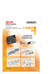
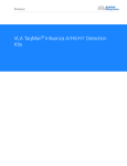
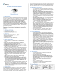
Revision 1.0 Base-Station User Manual Product name LogiTrack Base-Station user manual p/n Product rev. A01 Document p/n LT-D-0101 Document rev. 01 date 14/11/2011 Author name Golan K. Documents changes and version Date 14/11/2011 Name Golan K LogiTag Systems LTD Change description Document release version 10 2 עמוד 1. PRECAUTIONS Please read and understand this manual before using the products. Please consult your LOGITAG representative if you have any question or comments. 1.1 WARRANTY, LIMITATIONS OF LIABILITY WARRANTY: LOGITAG’S EXCLUSIVE WARRANTY IS THAT THE PRODUCTS ARE FREE FROM DEFECTS IN MATERIALS AND WORKMANSHIP FOR A PERIOD OF ONE YEAR (OR OTHER PERIOD IF SPECIFIED) FROM DATE OF SALE BY LOGITAG. LOGITAG MAKES NO WARRANTY OR REPRESENTATION, EXPRESS OR IMPLIED, REGARDING NON-INFRINGEMENT, MERCHANTABILITY, OR FITNESS FOR PARTICULAR PURPOSE OF THE PRODUCTS. ANY BUYER OR USER ACKNOWLEDGES THAT THE BUYER OR USER ALONE HAS DETERMINED THAT THE PRODUCTS WILL SUITABLY MEET THE PREQUIREMENTS OF THEIR INTENDED USE. LOGITAG DISCLAIMS ALL OTHER WARRANTIES, EXPRESS OR IMPLIED. LIMITATIONS OF LIABILITY: LOGITAG SHALL NOT BE RESPONSIBLE FOR SPECIAL, INDIRECT, OR CONSEQUENTIAL DAMAGES, LOSS OF PROFITS OR COMMERCIAL LOSS IN ANY WAY CONNECTED WITH THE PRODUCTS, WHETHER SUCH CLAIM IS BASED ON CONTRACT, WARRANTY, NEGLIGENCE, OR STRICT LIABILITY. IN NO EVENT SHALL THE RESPONSIBILITY OF LOGITAG FOR ANY ACT EXCEED THE INDIVIDUAL PRICE OF THE PRODUCT ON WHICH LIABILITY IS ASSERTED. IN NO EVENT SHALL LOGITAG BE RESPONSIBLE FOR WARRANTY, REPAIR, OR OTHER CLAIMS REGARDING THE PRODUCTS UNLESS LOGITAG'S ANALYSIS CONFIRMS THAT THE PRODUCTS WERE PROPERLY HANDLED, STORED, INSTALLED, AND MAINTAINED AND NOT SUBJECT TO CONTAMINATION, ABUSE, MISUSE, OR INAPPROPRIATE MODIFICATION OR REPAIR. 1.2 APPLICATION PRECAUTIONS, CHANGE IN SPECIFICATIONS SUITABLITY FOR USE: LOGITAG SHALL NOT BE RESPONSIBLE FOR CONFORMITY WITH ANY STANDARDS, CODES, OR REGULATIONS THAT APPLY TO THE COMBINATION OF THE PRODUCTS IN THE CUSTOMER'S APPLICATION OR USE OF THE PRODUCT. TAKE ALL NECESSARY STEPS TO DETERMINE THE SUITABILITY OF THE PRODUCT FOR THE SYSTEMS, MACHINES, AND EQUIPMENT WITH WHICH IT WILL BE USED. KNOW AND OBSERVE ALL PROHIBITIONS OF USE APPLICABLE TO THIS PRODUCT. NEVER USE THE PRODUCTS FOR AN APPLICATION INVOLVING SERIOUS RISK TO LIFE OR PROPERTY WITHOUT ENSURING THAT THE SYSTEM AS A WHOLE HAS BEEN DESIGNED TO ADDRESS THE RISKS, AND THAT THE LOGITAG PRODUCT IS PROPERLY RATED AND INSTALLED FOR THE INTENDED USE WITHIN THE OVERALL EQUIPMENT OR SYSTEM. CHANGE IN SPECIFICATIONS: PRODUCT SPECIFICATIONS AND ACCESSORIES MAY BE CHANGED AT ANY TIME BASED ON IMPROVEMENTS AND OTHER REASONS. CONSULT WITH YOUR LOGITAG REPRESENTATIVE AT ANY TIME TO CONFIRM ACTUAL SPECIFICATIONS OF PURCHASED PRODUCT. 1.3 DECLARATIONS EQUIPMENT MODIFICATION CAUTION: Equipment changes or modifications not expressly approved by LogiTag, could void the user's authority to operate the equipment and could create a hazardous condition. LogiTag Systems LTD 3 עמוד 1.4 SAFETY PRECAUTIONS This chapter provides important information for the safe use of this product. Ensure to read the information carefully before use. IN THE SAFETY PRECAUTIONS BELOW, SEVERITY IS CATEGORIZED AS EITHER”WARNING” OR “CAUTION”. WARNING Indicates a potentially hazardous situation which, if not avoided, could result in minor or moderate injury, or may result in serious injury or death. Additionally there may be significant property damage CAUTION Indicates a potentially hazardous situation which, if not avoided, may result in minor or moderate injury, or property damage. Property damage refers to extended damage caused to house/household goods or livestock/pets. Description of Symbols: Ensure to establish a solid grounding A label indicating that a device with a grounding terminal should always be grounded. Electric shock hazard A notification that alerts the possibility of electric shock under certain condition Do not disassemble. A notification that prohibits disassembly when injuries caused by electric shocks may result Prohibition Indicates an action or activity not permitted. Observe strictly LogiTag Systems LTD Indicates the need to ensure the safe use of the product . 4 עמוד WARNING Never disassemble, repair, or modify the main unit and cables. Do not disassemble, repair, or modify this product. Doing so may result in electric shock, fire, or personal injury. Do not handle the device with wet hands. Do not touch the terminals while the device is connected to the power supply. Electric shock hazard Do not allow the cables to be in contact with heaters The cable sheaths may melt and the exposed wire may cause electric shock or fire. Do not use the power cords and power adapters not supplied with the products. Failure to do so may results in electric shock, fire, or personal injury. Connect and disconnect cables as described in the following procedures when installing, moving, on this product or attached devices. To disconnect: 1. Attached all cables to devices. 1. Remove power cords from outlet. 2. Attached power cords to outlet. 2. Remove all cables from devices. Always turn OFF the power supply to the Base Station before attempting any of the following. Not turning OFF the power supply may result in malfunction or electric shock. LogiTag Systems LTD Assembling the Units. Connecting or disconnecting the Expansion I/O Units or Expansion Units. Connecting or wiring the cables. Connecting or disconnecting the connectors. 5 עמוד CAUTION Do not drop the device you may receive major shocks Doing so may result in personal injury or device damage Do not apply strong force to, or place heavy items on the device or cables. Doing so may deform or damage the device, resulting in electric shock or fire Use and store the product in an environment that is specified in the catalog or operation manual. Failure to do so may cause failure of the device, electric shock, or fire. Do not use or store the devices (Reader, antenna ,antenna cable) in the following locations: ・ Locations that do not satisfy the specified operating conditions (-10 to +50℃, 25%RH to 85%RH, noncondensing). ・ Locations that do not satisfy the specified storage conditions (-25 to +65℃, 25%RH to 85%RH, noncondensing). ・ Locations where the reader is exposed to direct sunlight. ・ Locations where the reader is exposed to dust, corrosive gas, saline, or flammable gas. ・ Locations where the reader is exposed to direct heat. ・ Locations subject to condensation due to high humidity. ・ Locations subject to vibration or impact that exceed the limits outlined in the specifications. Failure to do so may result in personal injury or device damage Be sure to tighten the devices screws securely. Cables with screw attachments must be secured before use. To avoid interferences with other systems, adhere to the following items and check them before using the product. Do not allow the device or cables to be exposed to water. If the device fails or is exposed to water (non-waterproof devices or parts), or an unusual smell, smoke, or sparks are detected, immediately refrain from using the device and contact LogiTag or a sales representative for service and repair. LogiTag Systems LTD Failure to do so may damage the device. The product uses a publicly available ISM frequency band of 433MHz to communicate with Tags. Some transceivers, motors, monitoring devices, power supplies (power supply ICs), and other similar RFID systems may generate noise, which cause radio interference and may affect communication with Tags. If the product is required in the vicinity of these items, check for any interference prior to use. On the contrary, the system itself may affect radio station transmissions or medical devices. Be cautious when using the system in the environments where such effects might occur. To minimize noise effects, adhere to the following: Establish a Class D grounding (former Class 3 grounding) for metal objects placed in the vicinity of the system. Keep cables away from those with high voltages or heavy currents. Doing so may result in electric shock, fire or failure of nonwaterproof devices or cables. Continued use of the failed device may result in electric shock or fire. 6 עמוד Do not use damaged cables. Be sure that all the mounting screws, terminal screws, and cable connector screws are tightened to the torque specified in the relevant manuals Be sure that terminal blocks and connectors are connected in the specified direction with the correct polarity. Not doing so may result in malfunction Do not apply voltages to the input terminals in excess of the rated input voltage. Do not apply voltages or connect loads to the output terminals in excess of the maximum switching capacity. When transporting the Units, use special packing boxes. Be careful not to apply excessive vibration or shock, or not to expose to water during transportation and not to drop the product. Do not use the system in an environment subject to flammable, explosive, or corrosive gases. Provide an enough space around the device for ventilation Continued use of the damaged cables may result in electric shock or fire . Incorrect tightening torque may result in malfunction. If the power supply for the I/O circuits is turned ON with the input and output connectors reversed, the fuse of output transistor may be blown. Excess voltages may result in burning. Excess voltage or loads may result in burning. Keep cables away from those with high voltages or heavy current. Properly shielded and grounded cables and connectors must be used for connection to host computer and / or peripherals. The machine installation, operation and maintenance should be carried out by “properly trained” person. LogiTag Systems LTD 7 עמוד 3. LOGITRACK BASE-STATION OVERVIEW The LogiTrack Base-Station is an Active-RFID transceiver designed to trigger RFID tags and received the information they send. The wireless infrastructure it generate enables a wide range of monitoring and tracing application, such as asset-management. The Base-Station has 2 RF modules in it: Transmission via 4 channels at 125Khzfrequency and 0.95W maximum power UHF Reception at 433Mhz via 2 channels The LogiTrack has the following communication interfaces: RS-232 Serial interface Ethernet adapter WiFi wireless interface LogiTag Systems LTD 8 עמוד 4. INSTALLATION AND USAGE GUIDE This installation and usage guide explains how to install the LogiTrack System and control the Base Station. 4.1 BEFORE YOU BEGIN 4.1.1 Installation Requirements Use the AC cable shipped with the LogiTrack Base Station. Use only authorized antennas and cables to conform to the local laws and regulations. Provide strain relief for all LogiTrack System connections. A Shielded Ethernet cable must be used to communicate with other devices . 4.1.2 Performance Considerations System performance may be affected by external factors including tag variables and environment. Performance tests conducted under typical operating conditions at your site are recommended to help you optimize system performance. Base Station performance may be affected by the following:: Metal surfaces such as desks, filing cabinets, bookshelves, and waste cans may enhance or degrade Base Station performance. Mount antennas (both LF and UHF) as far as possible from metal surfaces that are adversely affecting system performance. Devices that operate at the same UHF frequency, such as cordless phones and wireless home automation devices, can interfere with Base Station performance. These devices may degrade performance of the base station reader. Antennas operating in close proximity may interfere with one another, thus degrading reader performance. LogiTag Systems LTD 9 עמוד 5. BASE STATION SPECIFICATION 5.1.1 Base Station General Specifications Item Specification Power supply 100-240VAC Operating temperature -10° to 50°C (14° to 122°F) Humidity 25 to 85%RH non-condensing Storage temperature -25° to 65°C (-13° to 149°F) Dimensions L: 24.5cm / W: 13.2 cm / H: 5cm Protection class IP54, for Indoor use only Case material Aluminum Weight 1.35 Kg Mounting 2 point screw (M10) 5.1.2 LogiTrack Base Station Characteristics Item Specification UHF Center frequency 433/866/915Mhz (version dependent) UHF Power output Max 22dBm, (Changeable depending on the antenna.) UHF connectors antenna(s) SMA Type female located on the back side LF exciter operating frequency 125KHz (4x channels via internal multiplexer) LF Power output Up to 0.95W LF connectors antenna(s) Terminal Block Interfaces Digital Input IEEE802.3 compliance Ethernet IEEE802.11b WiFi Interface RS-232 Supported standard: o Baud rate: 112kbps o Data length: 7 / 8 bits o Parity: Even / Odd / None o Stop bit: 1 / 2 bit 4x Inputs (I1;I2;I3;I4) terminal block connector General purpose Relay 4x Relays (RL1; RL2; RL3; RL4) LogiTag Systems LTD 10 עמוד 5.1.3 Front Panel Configuration The Logi-Track includes 8 indication LEDs on its front panel. 1 – LF (125Khz) Transmission channel #1 is configured as ON 2 – LF (125Khz) Transmission channel #2 is configured as ON 3 – LF (125Khz) Transmission channel #3 is configured as ON 4 – LF (125Khz) Transmission channel #4 is configured as ON 5 – Tag received on the UHF channel 6 – Ethernet communication indicator 7 – Wifi communication indicator 8 – Power indication for the Base-Station LogiTag Systems LTD 11 עמוד 5.1.4 Back-Panel Configuration Back Side General purpose Relay Connector Input Connector UHF antenna connectors LF antennas connectors RS232 connector WiFi antenna connector ON/OFF switch AC Power input 100-240VAC 50-60Hz RJ45 Ethernet connector 5.1.5 UHF & LF Antenna Ports One or two UHF antennas can be connected to LogiTrack reader, depending on the application requirements. LF Antennae Ports UHF Antennae Ports IMPORTANT: Connect both LF & UHF antennae to the antenna ports before applying power to the base-station. Any antenna port that has detected no antenna will be disabled when the reader is powered on. LogiTag Systems LTD 12 עמוד 5.1.6 RS-232 Interface This port is used to connect the Base-Station to a host via serial RS-232 interface. If you use the PC as a host, prepare a cross cable to connect the PC to the port. 1; 2; 3 Pin assignment: Pin # 1 2 3 Name TX RX GND I/O Output Input - Function Transmit Data Receive Data Signal Ground Connecting to the PC example: PC D-sub 9 pin female (inch screw) Pin # Signal name Pin # Signal LogiTag Systems LTD 1 2 TX 1 3 RX 4 5 GND 2 6 7 8 9 3 TX RX GND LogiTrack RS232 Connector 13 עמוד 5.1.7 Ethernet Interface This port is used to connect the base-station to a host via standard Ethernet interface. The connector is a standard RJ45 one, with 2 indicative lights. Green LED: Link status Orange LED: Carrier detect 5.1.8 Inputs Interface The LogiTrack Base-Station includes 4 digital ports that can enable various trigger based applications. The connector is a terminal-block. That enables screwing in wires according to needs. Pin # 1 2 3 4 5 6 LogiTag Systems LTD Name I1 I2 GND I3 I4 GND I/O Input Input Input Input - Description Input port #1 Input port #2 Input port #3 Input port #4 - 14 עמוד How to wire a terminal block connector with signal cables(s) and how to connect it to the reader body. 1. Wire a signal cable(s) to the terminal block connector. 2. Loosen the cable fixing screw(s) (counterclockwise) and insert the signal cable(s) into the connector. 3. Tighten the cable fixing screw(s) (clockwise). 4. Mount the terminal block connector to the reader chasis. NOTE: Make sure to connect the signal cable to the terminal block connector prior to mounting the connector to the body. 5.1.9 AC Power Input The Base-Station is powered by 100-240VAC 50-60Hz via the AC cable provided with it. LogiTag Systems LTD 15 עמוד 5.1.10 General Purpose Relay Interface The LogiTrack Base-Station includes 4 dry-contact outputs that can be switched in various modes and trigger external devices RL1 The four general purpose relays are operation as dry contacts. Pin # RL1 RL2 RL3 RL4 Name Relay 1 Relay 2 Relay 3 Relay 4 Description Dry contact Dry contact Dry contact Dry contact How to wire a terminal block connector with signal cables(s) and how to connect it to the reader body. 1. Wire a signal cable(s) to the terminal block connector. 2. Loosen the cable fixing screw(s) (counterclockwise) and insert the signal cable(s) all the way into the connector. 3. Tighten the cable fixing screw(s) (clockwise). 4. Mount the terminal block connector to the reader body. NOTE: Make sure to connect the signal cable to the terminal block connector prior to mounting the connector to the body. LogiTag Systems LTD 16 עמוד