1
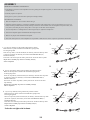
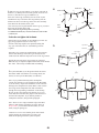
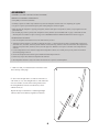
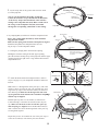
SWTC1600 - Blue
User ’s Manual
16’ Oval Trampoline
Model SWTC1600
__________
!
WARNING
Read all precautions and
instructions in this manual before
using this equipment. Save this
manual for future reference.
Maximum user weight 200 lbs.
!
IMPORTANT
Trampoline / Enclosure’s are
susceptible to winds. Be sure to secure your Trampoline / Enclosure.
Wind Damage is not covered in the
warranty of your trampo line.
ASSEMBLY
IMPORTANT ASSEMBLY INFORMATION
• Need phillips screw driver and 2 adjustable wrenches (putting the trampoline together). A rubber mallet may make assembly
easier, however.
• Assembly requires two persons.
• Wear gloves to protect your hands from pinch points during assembly.
TRAMPOLINE PLACEMENT
1. Place the trampoline on a level surface before using it.
2. Adequate overhead clearance is essential. A minimum of 24 feet from ground level is best. Provide clearance for wires, tree
limbs, and other possible hazards. Lateral (sideways) clearance is also essential. Place the trampoline away from walls, structures, fences, and other play areas. Always have a clear space on all sides of the trampoline.
3. Use the trampoline in a well-lighted area. Electric lights may be required for shady areas.
4. Secure the trampoline against unauthorized and unsupervised use.
5. Remove any objects from beneath the trampoline.
6. The owner and supervisors of the trampoline are responsible to make all users aware of practices specified in this manual.
1.
1. Lay two Top Tubes(1) on the ground in the position as shown
1
small hole
Make sure the Top Tube is turned so the small holes (spring holes)
are facing the ground
Insert one Top Tube (1) into the Socket(12) as shown(a), insert the other Top Tube
(1) into the T-joint(13) as shown(b), secure them with M8X60mm Bolt(17)
and M8 Locknut(18).
Then insert one end of Top Tube with T-joint into the Socket of other Top Tube
Key No1
18
12
1
small hole
a
17
Key No1
18
17
13
b
1
Repeat above assembly step until two assembly units(A)
will be completed
1
2.
Make sure the Top Tube is turned so the small holes (spring holes)
are facing the ground
Insert one Top Tube (2) into the Socket(12) as shown(a), insert the other Top Tube
(1) into the T-joint(13) as shown(b), secure them with M8X60mm Bolt(17)
and M8 Locknut(18).
Then insert one end of Top Tube(1) with T-joint into the Socket of the other
1
2
2. Lay two Top Tubes(1 and 2) on the ground in the position as shown
small hole
18
12
small hole
Key No2
18
13
a
17
Top Tube (2).
Repeat above assembly step until two assembly units(B)
will be completed
Key No1
b
17
2
1
3.
3. Lay two Top Tubes(2) on the ground in the position as shown
Make sure the Top Tube is turned so the small holes (spring holes)
are facing the ground
Insert one Top Tube (2) into the Socket(12) as shown(a), insert the other Top Tube
(2) into the T-joint(13) as shown(b), secure them with M8X60mm Bolt(17)
and M8 Locknut(18).
Then insert one end of Top Tube with T-joint into the Socket of other Top Tube
Repeat above assembly step until two assembly units(C)
will be completed
2
small hole
Key No2
18
12
17
a
Key No2
18
13
Notice:do not tighten the locknuts
2
11
2
small hole
b
17
2
3
4.Slide two Legs (4) into a Brace (3) as shown. The peak of
4.
Push Here
the Brace (3) should point toward the ground. Screw the two
Screws (7) into the two Legs (4) and Brace (3).
Insert one of the Legs (4) halfway into one of the T-joint
assembled in step 1. Insert the other Leg halfway into the
Socket Press down on both Legs at the same time and fully
insert them into the Sockets and T-joint
Note: You may need to pull outward on the Legs as you insert
them into the Sockets and T-joint
Then connect the leg and Top Tube by inserting
two M4X50mm Bolts(14), four M4 washer(16) and two M4
Locknuts(15)
3
4
Pull
Here
4
7
Peak
7
15
15
Pull
Here
16
1
14
16
(D)
14
Notice:do not tighten the locknuts
Repeat above steps until the six assembled leg sections (E)
have been completed as shown in next step.
5.Note: This step requires two persons. During this
step, you will connect the six assembled leg sections
together.
Push Here
1
1
Leg Section
5.
Small End
Large End
Leg Section
Stand three leg sections(E) and hold them in the positions
shown. Slide the large end of the leg section(E) into the
small end of the indicated Top Tube on one of the leg sections.
Small End
Leg Section
2
Repeat this step until all six leg sections are connected.
When this step is completed, tighten all the Bolts and Locknuts.
The frame will be fully assembled and freestanding
1
2
2
Large End
6.Lay the Bed (Mat) (5) on the ground inside the assem-
(E)
bled frame. Make sure that the two warning decals (not
shown) are on top of the Bed (Mat). (Not Shown.)
Note: If you purchased the Skywalker Trampoline
Combo, the enclosure was pre-installed on the Bed (Mat)
(5) at the factory. Inspect the attachments of the enclosure
Netting to the trampoline mat (bed). Make certain each of
the V-rings on the trampoline mat (bed) is threaded
through the corresponding “buttonhole” in the Netting.
Be sure to place the opening in the Netting so it is centered under the arch where the jumpers will climb off of
and onto the trampoline. If you did not purchase a
Trampoline enclosure, disregard this paragraph.
2
2
1
1
2
1
1
1
Note: There are 96 V-rings around the edge of the Bed
(Mat) (5) and 96 holes around the top of the frame. In
Steps 6 and 7 you will attach the Bed (Mat) (5) to the
frame, using 96 Springs (8).
Caution: It is wise to wear leather gloves while attaching the Springs. Be careful where you place your
hands as the Springs and frame joints can pinch.
V-rings
12
1
2
2
2
Attach the Springs (8) as follows: Hook one end of a
Spring (8) into a V-ring. (See the inset drawing.) Hook
the Spring Tool(11)(not shown) to the free end of the first
Spring (8). Use the Spring Tool(11) to pull the first Spring
until it reaches the frame. Push the end of the first Spring
into a hole in the frame. Unhook the Spring Tool
6.
14’direction
V-rings
8
8
Make sure the opening of
the enclosure and T-joint
are aligned
After you have hooked one Spring (8) into one of the Vrings on the Bed (Mat) (5), count exactly 24 V-rings and
24 frame holes in a clockwise direction. Attach a second
Spring to the V-ring and frame at this point. Count 24 Vrings and 24 frame holes in a clockwise direction and
attach a third Spring. Count 24 V-rings and 24 frame
holes in a clockwise direction and attach a fourth Spring.
7.After attaching the first four Springs (8), count exact-
ly 12 V-rings and 12 frame holes in a clockwise direction.
Attach another Spring to the V-ring and frame at this
point. Count 24 V-rings and 24 frame holes in a clockwise direction and attach another Spring. Count 24 Vrings and 24 frame holes in a clockwise direction and
attach another Spring. You will now have 8 evenly
spaced Springs (8) attaching the Bed (Mat) (5) to the
trampoline frame.
7.
V-ring
6
Attach eight Springs (not shown) evenly between the
eight attached Springs in the same manner as before.
Attach sixteen Springs (not shown) evenly between the
sixteen attached Springs.
16’direction
8
Frame
Inset drawing
Continue to attach the remaining Springs between the
previously attached Springs, until all Springs are
attached.
( Door of the Enclosure)
alk
er
6
yw
8.
Sk
Safety Note: For the Bed (Mat) (5) to have the even tension necessary for safety in jumping, the Springs (8)
must be attached as described. As you attach Springs,
carefully count the V-rings and frame holes. If a V-ring or
hole is skipped, reattach the Springs in the proper position.
8.Lay the frame Pad (6) on the frame. Adjust the posi-
(If you are using the Skywalker Trampoline Enclosure,
go to the Skywalker Trampoline Enclosure User’s
Manual, pages 8-11, for instructions in assembling the
Enclosure. The Enclosure must be assembled and secured
to the trampoline frame before proceeding further with
trampoline assembly.)
13
Sky
wa
lk
er
tion of the Frame Pad so that the slits are directly above
the Legs (4), as shown. Make sure the printing of the “
LOGO is located as shown.
4
Slit
Printing
Do not use the trampoline without the Frame Pad (6).
The Frame Pad is designed to reduce the possibility of
injuries due to jumpers coming in contact with the trampoline frame. If you do not have a Frame Pad, contact
your dealer to obtain one. Properly install the Frame Pad
before using the trampoline.
Refer to the inset drawing. Thread one of the inner frame
straps through a V-ring and tie down. Repeat this with all
the inner straps along the inside of the frame pad.
Attach the outer straps to the frame of the trampoline by
tying them down
Repeat this step with the remaining straps (not shown).
Frame
10. Using the included plastic tie, attach the Safety
(9) to the frame near the point where jumpers will climb
onto and off the trampoline.
The trampoline is now fully assembled. Make sure that
all parts are securely attached. Familiarize yourself and
all users of the trampoline with the safety precautions,
use and instructional materials, and care and maintenance
instructions in this manual before using the trampoline.
Placard
9
DISASSEMBLY (TAKING APART)
To disassemble (take apart) the trampoline, follow assembly steps 1 through 10 in reverse order. Do not attempt to
disassemble any frame parts before the springs and the mat have been removed. Use gloves to protect your hands
from pinch points while taking the trampoline apart.
14
Skywalker Trampolines 16x14 Ft. Oval Trampoline
Model:
SWTC1600 - BLUE
Key No
Part
Qty.
Description
1
2
3
4
5
6
7
8
9
10
11
12
13
14
15
16
17
18
4165
4166
4167
4168
7021
5054
1005
3010
9002
10013
20001
4169
4170
1071
1072
1073
1074
1075
6
6
6
12
1
1
12
96
1
1
1
6
6
12
12
24
12
12
Top Tube (with small hole)
Top Tube (with small arc)
Leg Brace
J-Shaped Leg Extension
Jump Mat w/96 V-Rings
Blue Frame Pad
#8 Sheet Metal Screw – Self Tapping Screw
Springs
Warning Label
Screwdriver
Spring Puller
T-Socket (pre-assembled to top tube at time of trampoline purchase)
T-Joint (pre-assembled to top tube at time of trampoline purchase)
M4x50 Bolt
M4 Lock Nut
M4 Washer
M8x60 Bolt
M8 Lock Nut
ASSEMBLY
ASSEMBLY (PUTTING THE ENCLOSURE TOGETHER)
IMPORTANT ASSEMBLY INFORMATION
• Need phillips screw driver (included).
• Assembly requires two adults. Keep children away from the trampoline enclosure until it is completely put together.
• Use gloves to protect your hands from pinch points while putting the enclosure together.
• Make sure that the trampoline is properly put together, with the frame pad correctly laid out, before you put together the trampoline enclosure.
• The assembly steps refer to parts by their descriptions and key numbers (see the PARTS LIST on page 13 and make sure that
all listed parts are included. If a part is missing, refer to ORDERING REPLACEMENT PARTS at the bottom of page 13.
TRAMPOLINE PLACEMENT
1. Place the trampoline and enclosure on a level surface before you use it.
2. Adequate overhead clearance is essential. A minimum of 24 feet (7.3 meters) from the ground is recommended. Provide clearance from wires, tree limbs, and other possible hazards. Lateral (sideways) clearance is also essential. Place the trampoline and
enclosure away from walls, structures, fences, and other play areas. Maintain a clear space on all sides of the trampoline and
enclosure.
3. Use the trampoline in an area with lots of light. If the trampoline is indoors or in a shady areas you may need to use artificial
(electrical) lighting in the area.
4. Secure the trampoline and enclosure against unauthorized and unsupervised use.
5. Remove any objects from under the trampoline and enclosure.
6. The trampoline enclosure is only to be used as an enclosure for a specific round trampoline.
1. Make sure that you understand the information in the
box at the top of this page.
2
6
2. Sleeve the Straight Tube (5) and Curved Tube (6)
with foam (8). Lay one Straight Tube (5) with foam and
one Curved Tube (6) with foam on the ground, insert
the StraightTube(5) into the curved tube(6), secure
with the screw(4).
Repeat this step to attach the five remaining Straight
Tubes(5) and Curved tubes(6) together (not shown).
5
4
8
3
7
V -ring
Warning label
3. Lay the Jump mat on the ground. Put enclosure mesh
(7) on the jump mat.
Note: If you purchased the Skywalker Trampoline
Combo, the enclosure was pre-installed on the Bed (Mat)
at the factory. Inspect the attachments of the enclosure
Netting to the trampoline mat (bed). Make certain each of
the V-rings on the trampoline mat (bed) is threaded
through the corresponding “buttonhole” in the Netting.
Jump mat
4. Lay Jumping Mat(5) with the net inside the trampoline frame.
14’direction
4
Notice: The warning labels lies midway on the maximum
long direction of frame.
Make sure the opeing of the enclosure and T-joint are aligned
Attach the Jump Mat to the trampoline frame by refer
ring to steps 6-7 in the trampoline manual.
Spring
Jump mat 7
V -ring
16’direction
5>Locating the jumping mat to the enclosure opening
Make sure the opening of
the enclosure and T-joint
are aligned
Holding the enclosure netting at the door zipper opening,
place the enclosure netting on top of the jump mat with the zipper
opening placed to the right of the v-ring that has the hook and
straps attached to it
Trampoline
frame
6
A
7
Hexagon hole
6. Attach the Frame Pad to the trampoline frame. Refer to
step 8-9 on page 13 in your trampoline manual for further instruction.
Note: There is a Hexagon hole on the pole cap (1) with a nut
inside as shown A. Insert the pole cap(1) though one strap
ring on the top edge of the enclosure mesh(7) as shown in
Inset Drawing B. Make sure the Hexagon hole side of the
cap is against the mesh, and the holes on both the strapshown
ring
and the caps are aligned.
Hold the pole cap close to a curved tube (6) with foam as
in Inset Drawing C. Insert the curved tube(6) into the pole
cap. Make sure the holes on the curved tube,pole cap
and strap ring are aligned. Insert the M5x50mm bolt(2)
until it touches the nut in the Hexagon hole of the pole cap,
securing them together.
Repeat this process to assemble the rest of the pole caps(1)
to the curved tubes(6) with foam by the same manner.
9
16’direction
Opening of
the enclosure
Holes
Spring
2
B
Hole
1
1
1
C
Strap
Hole
6
Strap ring
Inset drawing
6
6
Frame Pad
6
6
Enclosure Door
Poles
7
7. Note: In Step 6 you will secure the enclosure poles
to the frame of the trampoline.
Start from the enclosure door, lift one of the poles assembled
in Step 1, see the insert drawing. Insert the Straight Tube(5)
into the top hole of the Square Socket on trampoline frame
as shown. Make sure the bent side of the enclosure poles
are facing toward the center of the trampoline.
Enclosure
Door
Note: The end of the straight tubes(5) are sharp. Use
caution when assembling.
Pad
Repeat this process to assemble the remaining five poles
to the trampoline frame.
8
Inset drawing
Jump Mat
T -joint
Frame Pad
5
Socket
Leg
A
8 . Tie the straps that are sewn on the edge of the enclosure mesh around the outside of the cap. Make sure to
secure the knot tightly, see insert drawing A..
Note: The enclosure poles are high, be careful when
you attach the straps. If needed, please use a ladder.
10
Leg
Strap
1
6
1
Strap
9. Insert the end cap(3) into the bottom hole of the Socket.
9
socket
3
Insert end cap(3) into end of Socket
10
10. Your trampoline enclosure is now fully assembled
(put together). Make sure that all parts are securely
attached. Familiarize yourself and all users with the
trampoline and enclosure with the safety precautions,
use and instructional materials, and care and maintenance instructions in this manual before using the
trampoline and enclosure.
DISASSEMBLY (TAKING THE ENCLOSURE APART)
To disassemble the trampoline enclosure (take it apart), follow assembly steps 1 through 7 in reverse order.
11
Skywalker Trampolines 16x14 Ft. Oval Trampoline Enclosure
Models:
SWTC1600 - BLUE
Key No
Part No
Qty.
Description
1
2
8017
1016
6
6
3
4
5
6
7
8
9
8027
1005
4171
4172
6033
5001
10013
6
7
6
6
1
12
1
Blue Pole Cap
M5X50 Bolt
Lock Nut (pre-assembled in pole cap)
End Cap
#8 Sheet Metal Screws – Self Tapping Screws
Lower Enclosure Straight Tube
Upper Enclosure Curved Tube
Enclosure Netting
Foam
Screwdriver