1
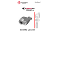
Application Manual for the Thermal-Eye™ Thermal Security Camera Copyright L3 Communications All Rights Reserved EXPORT CONTROL NOTICE – This technical data and software is considered as Technology Software Publicly Available (TSPA) No License Required (NLR) as defined in Export Administration Regulations (EAR) Part 734.7-11. PN 4000161-1 Rev C 2 WELCOME TO THE WORLD OF INFRARED! Worldwide Patent Rights Reserved. This product is covered by one or more of the following patents: U.S. Patent Nos.: 5,288,649; 5,367,167; 6,267,501; 6,586,831; 6,521,477; 6,690,014; 6,479,320; and under license to 5,196,703. Euro.Pat.Appln. 1159591. Additional Patents Pending. www.Thermal-Eye.com L3 Communications Infrared Products (L-3 IP) (Formerly Raytheon Commercial Infrared) 13532 North Central Expressway PO Box 741148, MS 37 Dallas Texas 75374 PN 4000161-1 Rev C 3 Important Safeguards WARNING WARNING: TO REDUCE THE RISK OF ELECTRIC SHOCK, DO NOT OPERATE WITH CAMERA COVER REMOVED. DO NOT OPEN COVERS AS THERE ARE NO USER-SERVICEABLE PARTS INSIDE. REFER SERVICING TO QUALIFIED SERVICE PERSONNEL. 1) Instructions: Read all safety and operating instructions before operating your Thermal Security Camera. 2) Cleaning: To clean camera housing, use only a soft cloth dampened with water. To clean camera lens, use a soft cotton cloth and mild neutral soap diluted with lukewarm distilled water (1 part soap to 100 parts water), followed by use cotton swab or lens cleaning cloth dampened with reagent grade isopropyl alcohol or acetone. Acetone will damage plastic components of the camera. 3) Servicing: Do not remove the cover. There are no user-serviceable parts inside. Refer all servicing to qualified service personnel. Opening the TSC4500 will void your warranty. 4) Power Sources: This product should be operated only from the type of power source indicated on the marking label. For products intended to operate from battery power, or other sources refer to the operating instructions. 5) Restriction of Use Environments: The unit is not intended or warranted for use in the following conditions. Damage resulting from such exposure would not be covered by the warranty. Unit is intended for outdoor applications. A solar shield is available to limit sun’s heating of the TSC4500 body. Unit is not intended to operate submerged in water. However, the TSC4500 is designed to withstand immersion or exposure to rain or high humidity. PN 4000161-1 Rev C 4 Unit is not intended for exposure to a salt-water atmosphere. Unit is not intended for dynamic–mount applications, such as on vehicles or heavy machinery, in which transmitted vibration is continuously sustained. Unit (whether powered On or Off) is not intended for viewing of direct or indirect (reflected) sunlight. Unit is intended for non-horizon exposure looking downward from intended mounting plane. Exposure to the sunlight, for even very short periods of time, may permanently damage the camera and therefore nullify any warranties. Unit is not intended for intentional or unintentional exposure directed towards solar activities, welding, or other activities of similar heat dynamics, which if performed may damage the camera and therefore will nullify any warranties. PN 4000161-1 Rev C 5 SECTION 1: INTRODUCTION ......................................... 6 INFRARED IMAGING .............................................................. 6 THE TSC4500TM PRODUCT LINE ........................................... 6 FEATURES AND OPTIONS: ............................................. 9 Performance................................................................... 11 Lens Option Capability for TSC4500............................. 11 Electrical........................................................................ 11 Interfaces ....................................................................... 11 Environmental................................................................ 11 Physical (25o HFOV) ..................................................... 12 Physical (12o HFOV) ..................................................... 12 SECTION 2: CARE AND MAINTENANCE.................... 13 CLEANING OF OPTICS ......................................................... 13 RESTRICTIONS OF USE ........................................................ 13 SECTION 3: INSTALLATION INSTRUCTIONS .......... 14 MOUNTING THE CAMERA ................................................... 14 SYSTEM INTERFACE CONNECTOR ....................................... 14 CONNECTING INPUT POWER ............................................... 15 VIDEO OUTPUT ................................................................... 16 USER INTERFACE WITH TSC4500 ....................................... 16 RS-232 Serial Communication: ..................................... 17 Using RS-232/485 Serial Communication:.................... 17 FOCUS ADJUSTING .............................................................. 18 PN 4000161-1 Rev C 6 SECTION 1: INTRODUCTION Infrared Imaging Visible light, the rainbow of colors that can be sensed by the human eye, is electromagnetic radiation within a certain frequency band. ‘Infra-‘ means ‘below’ and ‘red’ is the lowest frequency in the visible spectrum. Hence, ‘infrared’ (or ‘IR’) refers to that range of electromagnetic wavelengths just below that capable of sight by the human eye. In the IR range, energy from a scene is not sensed by sight ‘light but rather by temperature. Most objects that you see are not radiating visible light but instead, are reflecting light radiated from another source. Most objects have to be heated to extreme temperatures before they radiate energy in the visible light spectrum. However, energy in the infrared range is being radiated by all objects that are above absolute zero (-459F). Hence, everything has a thermal signature, regardless of light conditions. Your TSC4500 infrared detecting system distinguishes between very small differences in thermal (infrared) radiation, converts it to electrical signals, amplifies those differences, and reproduces them correspondingly in the visible light (video) range. Powerful advantages are achieved in being able to turn a pitch black night into a black and white TV image of the scene. As your infrared knowledge and experience grows, further applications will develop as you recognize heat clues beyond the naked eye in both day and night conditions. The TSC4500tm Product Line The Thermal Security Camera 4500 (TSC4500) is part of L3 Communications Infrared Products (L-3 IP) Thermal-EyeTM family of un-cooled infrared camera product lines. The TSC4500 utilizes amorphous silicon bolometer technology in a Long Wave Infrared (LWIR) camera designed as a drop-in replacement for CCTV cameras for new and existing security systems. The TSC4500 provides the advantage of viewing PN 4000161-1 Rev C 7 scenes in total darkness and in some conditions of smoke, dust and fog. Unlike many of the low-light security cameras, the TSC4500 does not require any kind of IR illuminator or any visible light. The TSC4500 camera operates with a 9-30 Volt DC. The TSC4500 camera offers an optional interface cable design that comes in a variety of lengths, 3ft, 15ft and 30ft, to allow the customer to integrate into their system. L-3 IP also offers an optional breakout interface cable to operate the TSC4500 camera. This cable facilitates the user for bench top checkout and also to power the camera with a 24VAC power converter kit available from L-3 IP to be compatible with most CCTV setups. The interface cable has flying leads (wires) for power, video on a BNC output, and a serial connector for RS-232 communication. The optional 24VAC power converter accessory allows the user the flexibility to easily install the camera into the many existing CCTV systems that use 24VAC. The 24VAC converter can be used in a user’s junction box with the standard interface cable or placed inside a weatherized enclosure. The TSC4500 camera model is rated IP67 and has an optional shroud cover compatible for outdoor solar shielding use. The TSC4500 camera model has an accessory Developer’s Kit that allows access by the user through the RS-232 Interface I/O to the following discrete controls: • Polarity (WHT, BHT) • E-zoom (1X, 2X etc.) • Shutter (the TSC4500 has a bi-phase shutter that can be commanded “closed’ to protect the FPA detector to solar exposure when power is OFF) & touch-up PN 4000161-1 Rev C 8 Also through the accessory, RS-232 GUI Developers Kit, user can setup the camera software with the following User Controllable Graphic User Interfaces: • User Parameter GUI • User Control GUI • Symbology GUI • Temperature Sense Color GUI • Image/Frame Capture GUI • Manual Gain/Level GUI • Manual Pixel Substitution GUI PN 4000161-1 Rev C 9 THERMAL SECURITY CAMERA FEATURES AND OPTIONS: Extended calibration for -20º to +70º C operating range Athermalized lens for self-focusing over temperature. TSC4500 Camera, 30Hz Video Lens Option Video Out 25° NTSC 25° PAL 12° NTSC 12° PAL TSC4500 Camera, 9Hz Video Lens Option Video Out 25° NTSC 25° PAL 12° NTSC 12° PAL Accessories and Cables, User Interface Cable, 3ft (.9m) 15ft (4.5m) 30ft (9.1M) Enclosure Interface Cable, 4in (.1m) AC/DC Converter Solar Shield Kit PN 4000161-1 Rev C 10 Optional Enclosure Window Kits & Part numbers For Pelco 2500 Series 4” dia. Window frame 4978525-1* or 4978525-2** For Pelco 3500 Series 2.9”x2.5” window frame 4978535-1* or 4978535-2** For Pelco 4700 Series 4.2”x3.9” window frame 4978547-1* or 4978547-2** For Universal Series 6”x6” window frame 4978540-1* (Note 2) or 4978540-2** * -1 Germanium Window (96% Trans in 7-14µm) 2.25” diameter ** -2 Silicon Window (73% Trans in 7-14µm) 2.25” diameter Note 1 – When the TSC4500 is used in an Enclosure, an infraredtransmitting window must be installed. Note 2 – Universal Series Enclosure kit is designed to fit the intended enclosure after being sized by the integrator. The window material is bonded to the frame after properly fitted using provided materials and procedural instructions. Application Note – the TSC4500 camera interface is RS-232 only. One camera, one GUI (no daisy chains). PN 4000161-1 Rev C 11 SPECIFICATIONS Performance Detector Type Format Spectral Response Detector NETD (typical) Uniformity, (typical) Time to Operation (typical) Uncooled Amorphous Silicon (320 x 240) pixel array 7 to 14 µm < 70 mK @ 25°C >90% @ 25°C, small area 4 seconds @ 25°C Lens Option Capability for TSC4500 Field of View (FOV) Range to detect Human Activity Focus 25o Lens 12o Lens 25° x 19° 12° x 9° 1465 Feet (445 m) Manual Adjust athermalized 3330 Feet (1015 m) Manual Adjust athermalized Electrical Power Source Power Consumption (Typical) NOTES 1 Class 2, 9-30V DC1 < 2W DC @ 12VDC Using a 30V DC supply and 18AWG wire, it is recommended that the power supply wires are no longer than 1000 feet. Interfaces Video Output Video Field Rate Serial Communications NOTES NTSC (Monochrome SMPTE-170M) and PAL models available 60 Hz RS – 232 Environmental Operating Temperature – Thermal-Eye TSC4500 Storage Temperature -20° to +70°C (-4° to 158° F) -40° to +105°C (-40° to 221° F) PN 4000161-1 Rev C 12 Water resistance Operating Humidity IP67, IEC pub. 529 0 – 95% (non-condensing) Physical (25o HFOV) Thermal-Eye TSC4500 w/25º lens 8.3” x 2.6” x 2.5” [210.8 x 66.0 x 63.5] Dimensions Weight Mounting Provisions ¼-20 top or bottom mounting bracket (using the same mounting bracket by sliding onto camera body) Physical (12o HFOV) Dimensions Weight Mounting Provisions Thermal-Eye TSC4500 w/12º lens 8.3” x 2.6” x 2.5” [210.8 x 66.0 x 63.5] 1/4-20 top or bottom mounting bracket (using the same mounting bracket by sliding onto camera body) Customer Service L3 Communications Infrared Products (L-3 IP) personnel and dealers are trained to help you install and use our Thermal-Eye TSC4500 line of products. If you have questions or comments, please call L-3 IP Customer Service at 972-528-1300 or toll free at 800-990-3275. EU Representative BFi OPTiLAS INTERNATIONAL SA Z. I. La Petite Montagne Sud 4 allée du Cantal – 91018 EVRY CEDEX France Phone: 33 - (0) 1 60 79 59 55 PN 4000161-1 Rev C 13 SECTION 2: CARE AND MAINTENANCE Cleaning of Optics The lens assembly is a long wave thermal imaging objective lens that collects and focuses radiation in the 7–14 µm spectral region. The optical surface of the lens should only be cleaned when visibly dirty. Care should be taken to avoid touching the exposed lens face. Skin acid left behind with fingerprints can be damaging to coatings and lens substrates. First use a jet of air or blow across the surface to remove any sand or abrasive particles before cleaning. If oil, water spots, or fingerprints form on the optical surface, clean as soon as possible using a soft cotton cloth and mild neutral soap diluted with lukewarm distilled water (1 part soap to 100 parts water), followed by reagent grade isopropyl alcohol or acetone swab. Dust can also be removed gently using an alcohol or acetone swab. Note: Avoid swabs that incorporate plastic stems, as some plastics will dissolve dissolve in alcohol or acetone. acetone Restrictions of Use The unit is not intended or warrantied for use in the following conditions. Damage resulting from such exposure would not be covered by the warranty. Unit is compatible with outdoor applications with the optional sun shroud. Unit is not intended for exposure to a salt-water atmosphere. Unit is not intended for dynamic–mount applications, such as on vehicles or heavy machinery, in which transmitted vibration is continuously sustained. Unit (whether powered On or Off) is not intended for viewing of direct or indirect (reflected) sunlight. Unit is intended for non-horizon exposure looking downward from intended mounting plane. Exposure to the sunlight, for even very short periods of time, may permanently damage the camera and therefore nullify any warranties. PN 4000161-1 Rev C 14 Unit is not intended for intentional or unintentional exposure directed towards solar activities, welding, or other activities of similar heat dynamics, which if performed may damage the camera and therefore will nullify any warranties. SECTION 3: INSTALLATION INSTRUCTIONS Mounting the Camera The removable mount assembly is made up of an extrusion that can be locked in place by two setscrews. Each extrusion is designed to fit into the grooves on the top and bottom of camera housing. The mount can easily be removed and placed on either the top or bottom of the camera housing. See Figure 1. Figure 1 – Mounting bracket on Thermal-Eye TSC4500 System Interface Connector The TSC4500 uses a commercially available connector to provide interface with the user’s system utilizing L-3 IP’s interface cable. Conxall PN CXS3106A2027S300 PN 4000161-1 Rev C 15 Figure 2 – Camera Interface Connection Connecting Input Power The TSC4500 uses DC power into the interface connector: The camera connector on the TSC4500 camera utilizes a DC power input rated for a nominal 12, 18 or 24 VDC supply. For DC power, use only an isolated Class 2 power supply rated for at least 2 Watts. See Figure 3 for the wire color scheme and DC connection schematic of the interface cable. Figure3 – Interface Cable Schematic PN 4000161-1 Rev C 16 See Figure 4 for the wire color scheme and DC connection schematic of the interface cable. Figure 4 – Breakout Interface Cable Schematic Video Output The Thermal-Eye TSC4500 outputs AC-coupled, Monochrome SMPTE – 170M compatible video, which is compatible with NTSC. The video is output on a BNC connector and should be hooked up to a 75-ohm impedance monitor. If user employs a video grounded loop, the video ground connection going to this camera should be disrupted or not terminated. User Interface with TSC4500 Communication software may be commercially available to interface with and control Thermal-Eye TSC4500 Full Function cameras. The EIA/RS-232 serial port is necessary to utilize any such software packages. For information on compatible software to communicate with the Thermal-Eye TSC4500 Full Function cameras, please call our Customer Service at 1-972-528-1300 or toll free at 1-800-990-3275. PN 4000161-1 Rev C 17 RS-232 Serial Communication: The TSC4500 connector provides access to an EIA/RS-232 serial port for User interfacing. How to connect to this serial port is described below. Also see Figure 3, Figure 4 and Figure 5. The connections needed for RS-232 communications are provided in the three wires RS-232 DATA-, RS-232 DATA+, and SIGNAL GROUND. RS-232 DATA+ To TSC4500 DATA -SIGNAL GND Figure 5 – RS-232 Connections for the TSC4500 Using RS-232/485 Serial Communication: An RS-485 to RS-232 converter can be used to connect to a PC (for example, the B&B ElectronicsTM p/n 485SD9RJ). Category 5 (“Cat 5”) cable is recommended for the carrying the RS-485 signals to the converter & PC. Follow the directions for your particular RS-485/RS-232 device to correctly connect it to the Thermal-Eye TSC4500 data lines see Figure 6 and 7. RS-232/485 RS DATA+ To TSC4500 RS DATA-SIGNAL GND Figure 6 – RS-232/RS-485 Connections for the TSC4500 PN 4000161-1 Rev C 18 RS-485 DATA+ RS-485 DATA_ RS-485/232 Converter To a PC Serial port SIGNAL GROUND Figure 7 – RS-485 Connections to the PC Focus Adjusting The 25° and 12° Field of View lenses are manually focused lenses. These lenses are also athermalized and maintain focus over temperature extremes. PN 4000161-1 Rev C 19 SECTION 4: WARRANTY INFORMATION THERMALTHERMAL-EYE THERMAL SECURITY CAMERATM L3 COMMUNICIATIONS INFRARED PRODUCTS Repaired equipment should be returned prepaid (surface freight only). If goods are being returned from outside the United States, the shipper is responsible for all customs and brokerage charges. Warranty Product(s) will conform to L-3 IP’s current drawings and specifications at the time of delivery and be free from defects in material and workmanship under normal use and service for twelve (12) months, beginning on the date the product is delivered to the customer, or beginning on the date product is placed into service; collectively whichever is the shorter period of time, but in no event shall the period become greater than eighteen months (the “warranty”). L-3 IP’s sole obligation, buyer’s exclusive remedy, under the warranty is for L-3 IP, at its option, to repair or replace any part of the product which fails to meet the warranty or refund buyer’s purchase price, in the form of credit. For warranty repairs/replacements, at L-3 IP’s cost for shipping, buyer shall return product(s) to L-3 IP’s facility designated by L-3 IP, with a written explanation of failure. The warranty shall not apply to products; (i) used for purposes for which they are not designated or intended, or (ii) which have been repaired or altered without L-3 IP’s prior written consent, or (iii) which have been subjected to misuse, negligence, accident or improper maintenance or installation, or (iv) upon L-3 IP’s examination, do not disclose to L-3 IP’s satisfaction nonconformance to the warranty. In the event the product ‘warranty card” is not returned to L-3 IP, proof of purchase shall be required to effectuate the warranty provisions stated herein above. NO OTHER WARRANTIES, EXPRESS OR IMPLIED, ARE MADE WITH RESPECT TO THE PRODUCT(S) INCLUDING, BUT NOT LIMITED TO, ANY IMPLIED WARRANTY OF MERCHANTABILITY, NON-INFRINGENT OR FITNESS FOR A PARTICULAR PURPOSE. Buyer agrees that any documentation and / or representation provide to its customer(s) shall include the preceding advisement by L-3 IP. PN 4000161-1 Rev C 20 Warranty Card information can be filled out online at www.thermal-eye.com, select Support and select Thermal-Eye Product Warranty Card. IN NO EVENT SHALL L-3 IP OR ITS LICENSORS BE LIABLE FOR INDIRECT, INCIDENTAL OR CONSEQUENTIAL DAMAGES, LOSS OF PROFITS, LOSS OF USE OR DATA OR INTERRUPTION OF BUSINESS, WHETHER UNDER THEORIES IN TORT, CONTRACT OR OTHERWISE, EVEN IF L-3 IP OR ITS LICENSORS HAVE BEEN ADVISED OF THE POSSIBILITY OF SUCH DAMAGES. PN 4000161-1 Rev C 21 5. Reason for return Date and place of purchase Installation date Returned unit serial number Description of problem Return Authorization Number Fill out customer return form on last page and include it with the equipment being returned. A. B. C. D. E. F. HOW TO RETURN PRODUCTS FOR WARRANTY REPAIR: 1. Return the product to your Authorized Dealer. Dealer will notify the service department by telephone at 800–990–3275 or 972-528-1300 before returning any product. 2. A Return Authorization (RA) number will be assigned by the service department. This number must be marked clearly on the outside of the package being returned. 3. Service department will provide a shipping address. 4. The following information must be included on the packing slip: PN 4000161-1 Rev C 22 2) Your shipping address 4) your fax and telephone number 6) Name of the point of contact You will be asked for payment of an evaluation fee prior to us starting work. Following evaluation, when the extents of the repairs are known, L-3 IP will contact you and estimate the total cost of the repair. If you choose not to have the repair completed, you will still be liable for the evaluation fee. If you choose to authorize the repair, the camera will be repaired and returned following receipt of payment. You will need to provide the following information: 1) Model and serial number of camera 3) Your billing address (if different) 5) Description of the failure TELE: 972-528-1300 or toll free at 800-990-3275; FAX: 972-528-1529; www.thermal-eye.com Dallas, TX 75374-1148 PO Box 741148, M/S 37 L3 Communications Infrared Products Following expiration of the warranty period, the owner is financially obligated to pay for any repairs which are required. You may either return the camera to the sales dealer and the dealer will take care of it, or you may work with L-3 IP directly. If you choose to deal directly with L-3 IP, you may contact us at HOW TO RETURN PRODUCTS FOR “OUT OF WARRANTY” REPAIR: PN 4000161-1 Rev C 23 PN 4000161-1 Rev C 24 Thermal-Eye TSC4500 Customer’s Record Card Registered Owner/Agency/Company ________________________________________ Contact Person ________________________________________ phone/e-mail _____________________________ Authorized Dealer _________________________________________ phone/e-mail ______________________________ purchase date ____ / ____ / 20____ Thermal-Eye TSC4500 Serial Number _______ Model No. _______________________________ Camera location _________________________ _________________________________________ Notes: __________________________________________ __________________________________________ __________________________________________ __________________________________________ __________________________________________ __________________________________________ __________________________________________ __________________________________________ User: Please retain this card for your records, and fill out the Warranty Card online at: www.thermal-eye.com, select Support and select Thermal-Eye Product Warranty Card PN 4000161-1 Rev C 25 . PN 4000161-1 Rev C 26 COPYRIGHT 2007 ALL RIGHTS RESERVED The Thermal-Eye branding mark is a trademark of L-3 CIP. For further information on L-3 Communications Infrared Products, call 800-990-3275 (USA) or 972-528-1300 (Intl), or visit www. thermal-eye. com.