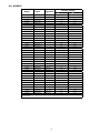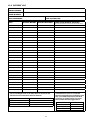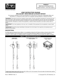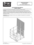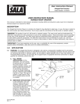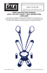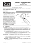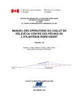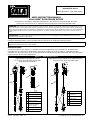
1
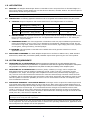
Rollgliss®
R520 Escape Device
Model Numbers: (See back pages.)
User Instruction Manual
Rollgliss® R520 Escape Device
This Manual is intended to meet the manufacturer’s instructions as required by EN 341:2011.
It should be used as part of an employee training program as required by AS/NZS 1891.
WARNING: This product is part of an emergency rescue system. The user must follow manufacturer’s instructions for each
part of the system. These instructions must be provided to the user of this equipment. The user must read and understand
these instructions before using this equipment. Manufacturer’s instructions must be followed for proper use and maintenance
of this equipment. Alterations or misuse of this equipment, or failure to follow instructions, may result in serious injury or
death.
IMPORTANT: For further information and questions on the use, care or suitability of the R520 Escape Device for your
application please contact Capital Safety.
This instruction describes installation and use of the Rollgliss R520 Escape Device. This instruction should be
read and understood before using the R520 and used as part of an employee training program.
IMPORTANT: Before using the R520 Escape Device, record the product identification information from the ID label into the
Inspection and Maintenance log in this manual.
description:
The R520 Escape Device (Figure 1) is available for Descent application only. The R520 can be installed in a
mountable box for bucket truck applications (rope lifeline lengths up to 150 m [492 ft]; rope lifeline length
capacities vary by rescue box). It can be also be stored in a backpack style bag when used with long rope lifeline
lengths and non-bucket truck applications.
Figure 1 - R520 Escape Device
Rollgliss R520 Bucket Truck Application Models,
Rollgliss R520 Long Rope and Non-Bucket Truck Application Models,
5 m (16.4 ft) to 150 m (492 ft) Rope Lifeline Lengths
(length capacity varies by Rescue Box)
5 m (16 ft) to 150 m (492 ft) Rope Lifeline Lengths
B
B
A
A
C
C
H
F
F
D
D
G
E
Form: 5903417 Rev: A
A
R520 Descent Unit
B
Body Connector
(Carabiner)
C
Labels
D
Rope Lifeline
Lifeline Connector
E
Lifeline Connector
Mountable Rescue Box
(shown mounted on
bucket truck G)
F
RFID Tag
A
R520 Descent Unit
B
Anchorage Handle
C
Labels
D
Rope Lifeline
E
F
G
Bucket Truck
H
RFID Tag
E
© Copyright 2012, DB Industries, Inc.
1.0Application
1.1Purpose: The Rollgliss R520 Escape Device is intended to lower one person from an elevated height to a
lower rescue station. Several people may use the device to descend, one after another. The descent speed is
automatically limited during the descent.
WARNING: The Rollgliss R520 Escape Device must not be used as a fall arrest device.
1.2LIMITATIONS: The following application limitations must be recognized and considered before using this product:
A.CAPACITY: Required capacities and descent distances for the Rollgliss R520 are as follows:
Users
Total Weight
(including tools, clothing, etc.)
Max. Descent Distance
Number of Descents
1 Person
59 kg (130 lbs) - 150 kg (331 lbs)
150 meters (492 ft)
6
1 Person
59 kg (130 lbs) - 100 kg (220 lbs)
150 meters (492 ft)
9
1 Person
59 kg (130 lbs) - 75 kg (165 lbs)
150 meters (492 ft)
12
B. DESCENT SPEED: The speed at which the user(s) will be lowered when using the Rollgliss R520 Escape
Device increases with the weight of the user. The approximate descent speed is 0.6 - 0.9 meters per
second (2 - 3 ft per second).
C. HAZARDOUS AREAS: Use of this equipment in hazardous areas may require additional precautions to
reduce the possibility of injury to the user or damage to the equipment. Hazards may include, but are
not limited to: high heat, caustic chemicals, corrosive environments, high voltage power lines, explosive
or toxic gases, moving machinery, and sharp edges.
D. TRAINING: This equipment is intended to be installed and used by persons trained in its correct
application and use.
1.3 Applicable Standards: The R520 Rollgliss Escape Device conforms to EN 341:2011, ANSI standard
Z359.4 2007, NFPA 1983, and federal (OSHA) standard requirements governing the use of this product.
2.0 System Requirements
2.1 COMPATIBILITY OF COMPONENTS: DBI-SALA equipment is designed for use with DBI-SALA approved
components and subsystems only. Substitutions or replacements made with non-approved components or subsystems
may jeopardize compatibility of equipment and may effect the safety and reliability of the complete system.
2.2 COMPATIBILITY OF CONNECTORS: Connectors (hooks, carabiners, D-rings) used to suspend the
R520 Escape Devices must be capable of supporting at least 15 kN (3,100 lbs). Connectors must be
compatible in size, shape, and strength. Non compatible connectors may unintentionally disengage (rollout). Roll-out occurs when interference between the connector and anchorage connector causes the hook
or carabiner gate to unintentionally open and release. Self locking snap hooks and carabiners must be used
with this system to reduce the possibility of roll-out. Do not use connectors that will not completely close
over the attachment element.
2.3 ANCHORAGE STRENGTH - R520 Escape Device: Anchorages used to suspend the R520 Escape Device
must sustain static loads applied along the axis of the device. When more than one R520 Escape device is
attached to an anchorage the anchorage strength requirement must be multiplied by the number of descent
devices attached to the anchorage. It is recommended that the strength of the attachment be at least
15 kN or (3100 lbs). If being used in Europe the attachment strength should be at least 10 kN (2248 lbs)
and conform to EN795. If being used in Australia or New Zealand the anchorage strength should be at least
12 kN (2700 lbs.) and conform to AS/NZS 1891.
WARNING: If greater anchorage strength requirements apply where the Rollgliss R520 Rescue Device will be used,
anchorages must comply with that requirement.
It is the responsibility of the user and purchaser of this equipment to be trained in the correct care and use
of this equipment. The user and purchaser must be aware of the operating characteristics, application limits,
and consequences of improper use of this equipment.
Warning: Training must be conducted without exposing the trainee to a fall hazard. Training should be repeated on a periodic basis.
2
3.0 Installation and use
3.1 Before each Use: Carefully inspect the R520 Escape Device in accordance with Section 5 of this
manual.
3.2Planning: Plan your emergency escape system and how it will be used before starting your work.
Consider all factors that will affect your safety before, during, and after an escape. Consider the following
when planning your system:
A.ANCHORAGE: Select a rigid anchorage point that is capable of supporting the load as specified in
Section 2.3 of this document.
B. DESCENT PATH AND LANDING AREA CLEARANCE: The planned descent path must be unobstructed and the
landing area must be clear of obstructions to permit safe landing of the user. Failure to provide an unobstructed
descent path and landing area may result in serious injury. Maintain a minimum distance of 31 cm (12 in) from
any vertical surface to ensure a safe descent.
C. TESTING THE SYSTEM: DBI-SALA recommends performing a test descent using a 55 kg (120 lb)
weight. The descent speed should be uniform and allow the user to reach the landing area safely. A
further check may be carried out by pulling the descent rope through the device while turning the rope
sheave. The twin brake pinion shafts will be visible and should be turning. This provides visual evidence
that both brake drum assemblies are operational. If one or both of the shafts do not turn, the R520
must be removed from service and tagged out.
Note: Record descents in the Descent Log in this manual.
D.SHARP EDGES: Avoid using this equipment where system components will be in contact with
unprotected sharp edges. An edge protector (Figure 2, part number 3320003) or protective padding
must be used when ascending over any edge.
3.3 Installation: The Rollgliss R520 Escape Device is available in several configurations. Installation
procedures vary depending on the intended application of the device.
• Connection to an anchorage: The Rollgliss R520 Escape Device may be attached to an anchorage
by connecting the unit’s carabiner directly to a D-ring or anchor strap that has been attached to the
structure (Figure 3). See Section 2 for compatibility and anchorage strength requirements.
Figure 2 - Edge Protector
Figure 3 - Connecting the R520 Escape Device to Anchorage
Anchorage
Connector
Anchorage
Connector
Anchorage
Anchorage
Anchorage
Carabiner
Anchorage
Connector
(Web Sling)
Carabiner
Web
Lanyard
3
• Connection to a EPV/EWP rescue box (replace old system): The Rollgliss R520 Escape Device may
be used to replace an old system in an existing rescue box. A hammerlock is used to connect the R520
anchorage handle to the U-bolt in the rescue box. See Section 2 for compatibility and anchorage strength
requirements. Rope lifeline length capacities vary by rescue box.
• Installed with New Rescue Box: The Rollgliss R520 Escape Device may be used with an optional DBI
Sala Rescue Box for bucket truck applications (Figure 4). Various rope lifeline lengths (up to 25 m [82
ft]) are available in kit form with the Rescue Box. To install Rescue Box option:
important: The following Rescue Box installation steps describe suggested component locations and
procedures. The installer must determine the best component locations and installation method based on the
specific design of the truck’s bucket and anchorage strength requirements discussed in Section 2 of this manual.
Read and understand all Steps below completely before starting installation. The U-bolt must be secured
through a member of sufficient strength within the bucket truck box.
Step 1. The upper Rescue Box cover (A) mounts to the bucket truck box with four M10 bolts and Nylock
nuts (B, not included). Use washers under the bolt heads and nuts. The position of the upper
Rescue Box cover on the bucket truck box shown in Figure 4 is approximate. (See “Important”
above.) Four bolt location holes are predrilled in the cover. Drill out these holes to accept M10
bolts if their location in the cover is acceptable, or drill new holes in the cover where they are
required for satisfactory cover installation. Use the cover as a template to mark drill holes in
the truck’s bucket box. Install bolts, washers and Nylock nuts. Tighten all four nuts securely.
Step 2. Locate the installation position of the large U-bolt (C) so that it will not interfere with the lower
Rescue Box cover when the cover is locked with the retaining pin (F; see Step 3). Drill two
holes for the U-bolt through the upper Rescue Box cover and the bucket truck box. Assemble
the included hammerlock (D) so that the U-bolt is inserted through the top loop of the
hammerlock and the connector of the R520 unit is inserted through the lower loop. The U-bolt
is then loosely fastened to the Rescue Box cover and bucket truck with washers and nuts.
Step 3. When fully assembled, the stud (E) in the lower Rescue Box cover must align with the hole in
the upper Rescue Box cover and also protrude through the bucket truck box. Push the upper
Rescue Box cover away from the bucket truck box to allow a hole to be drilled in the bucket
truck box at the location of the stud. After drilling the hole, confirm that the stud in the lower
Rescue Box cover can pass through the upper Rescue Box cover and the side of the bucket
truck box. The retaining pin (F) must be inserted through the stud to secure the lower section
of the Rescue Box to the upper Rescue Box cover and bucket truck box.
Figure 4 - Rescue Box Installation on Bucket Truck
Step 2
Step 1
Step 3
Step 4
E
B
C
D
A
4
F
Step 4. Remove the retaining pin so that the lower section of the Rescue Box can be removed. Pull
one end of the rope lifeline through the R520 unit until only a foot of lifeline remains at one
end. Carefully coil up the remainder of the lifeline and insert in the lower section of the Rescue
Box as shown. The lifeline must be capable of deploying completely without tangles or snags.
Secure the lower section using stud (E) and retaining pin (F).
• Supplied in backpack bag: The R520 Escape Device can be supplied in kit form, with accessories and
various rope lengths, for storage in a backpack style bag.
3.4 single person unassisted Escape: Procedures for performing and unassisted descent with the
R520 Escape Device are as follows:
WARNING: The users of this equipment must be in good physical condition. The user must have the ability to absorb the landing.
Step 1. Connect to a Full Body Harness or other
Body Support: A full body harness or other
means of supporting the user must be used
with the R520 Escape Device.
Figure 5 - Connecting to a Full Body Harness
Back
D-Ring
WARNING: Do not use a body belt with this
equipment. Body belts do not support your
entire body, which may result in serious injury.
When using a full body harness, connect
the Snap Hook on the lifeline to the front or
back D-ring (Figure 5). Ensure the D-ring is
positioned to hold the user upright. See the
full body harness manufacturer’s instructions
for more information.
Front
D-Ring
Step 2. Prepare the Lifeline: Pull out the pin that
secures the lower Rescue Box body (Figure
4 F). Allow the lower Rescue Box body to fall
away. Lower one end of the lifeline to the
ground or landing below. Ensure the lifeline
is free of knots or kinks.
Step 3. Prepare for Descent: Prior to descent, the
section of the lifeline between the user and the
R520 Escape Device must be tightened to remove
any slack. Tighten the lifeline by pulling on the
free end of the rope until slack between the user
and R520 Escape Device is removed. Once the
lifeline is taut, hold the free end of the lifeline
tightly until descent is initiated.
Figure 6 - Descent Control
note: When initiating a self-rescue from a bucket
truck (EWP) after connecting to the life line, the user
should limit the slack in the lifeline. This will reduce
stress on the user when initiating the descent.
Step 4.
Descend to Safety: Release the free end of the
lifeline to initiate descent. Descent speed will be
automatically controlled to a rate of .6 - .9 m/s
(2-3 ft/s) by the R520 Escape Device’s centrifugal
brake.
A
B
Note: Users should not hold the lifeline unless
attempting to slow or stop descent. Descent may be
interrupted by firmly grasping the free end of the
lifeline. (A, Figure 6)
For increased ease of control of descent speed,
the free end of the lifeline can be looped through
notch (B, Figure 6) on the same side of the unit.
Apply pressure to the free end of the lifeline during
descent to control descent speed.
Bend your knees to prepare for landing. After landing, disconnect the lifeline from the body
support.
5
Step 5. Prepare for the Next Descent: After use of the R520 Escape Device, the lifeline must be pulled
through the device as needed to position a lifeline end and Snap Hook adjacent to the next person
to descend.
4.0Training
It is the responsibility of the user and purchaser of this equipment to be trained in the correct care and use
of this equipment. The user and purchaser must be aware of the operating characteristics, application limits,
and consequences of improper use of this equipment.
Warning: Training must be conducted without exposing the trainee to a fall hazard. Training should be repeated on a periodic basis.
5.0Inspection
To ensure safe, efficient operation, the R520 Escape Device should be inspected at intervals defined in
Section 5.1. See Section 5.3 for inspection procedures.
5.1Frequency: In addition to inspecting the R520 Escape Device prior to each use, Inspection should be
performed at the following regular intervals:
• Monthly: A formal inspection should be completed by a competent person1 other than the user. A formal
inspection should be completed if the system parameters are changed, such as after a system is moved,
Re-rigged, anchorages moved, etc. Extreme working conditions may require increasing the Inspection
frequency. Inspect the R520 Escape Device in accordance with Section 5.3 and Section 5.4. Record
inspection results in the Inspection and Maintenance Log, or use the i-Safe™ inspection web portal to
maintain inspection records (see Section 5.2).
• Every Two Years: The R520 Escape Device must be sent to an authorized service center for inspection
and service (see Section 6.2).
5.2 i-Safe™ RFID Tag: R520 Escape Devices are equipped with
an i-Safe™ Radio Frequency Identification (RFID) tag (Figure 7).
The i-Safe™ RFID tag on the R520 Escape Device can be used
in conjunction with the i-Safe handheld reading device and the
web based portal to simplify inspection and inventory control
and provide records for fall protection equipment. If you are a
first-time user, contact a Customer Service representative in the
US at 800-328-6146 or in Canada at 800-387-7484. If you have
already registered, go to: http://isafe.capitalsafety.com. Follow
the instructions provided with the i-Safe handheld reader or on
the web portal to transfer your data to the web log.
Figure 7 - i-Safe™ RFID Tag
5.3Inspection steps: Per the intervals defined in Section 5.1, inspect the R520 Escape Device as follows:
Step 1.Inspect device for loose fasteners and bent or damaged parts.
Step 2. Inspect device housing for distortion, cracks, or other damage. Ensure the anchorage handle is
not damaged or distorted.
Step 3. The rope lifeline must pull through the device. Inspect the entire lifeline for cuts, burns, severely
abraded areas, and excessive wear.
Step 4. Device labels must be present and fully legible (see Section 8).
Step 5. Inspect for corrosion on the device.
Step 6. Inspect carabiners for damage, corrosion, and working condition.
Step 7. Inspect all system components and subsystems according to manufacturer’s instructions.
1 Competent Person: Person who is knowledgeable of the current periodic examination requirements, recommendations and
instructions issued by the manufacturer applicable to the relevant component, subsystem or system.
6
Step 8. Record inspection results in the Inspection and Maintenance Log (Section 10) or on the i-Safe web
portal (Section 5.2).
5.4 Unsafe or defective conditions: If inspection reveals an unsafe or defective condition, remove the
device from service and contact an authorized service center for repair.
6.0Maintenance, Service, Storage
6.1MAINTENANCE:
• Rollgliss R520 Escape Device: Periodically clean the exterior of the R520 Escape Device with water
and mild detergent. Position the device so excess water will drain out. Clean labels as required. Clean
rope lifeline with water and mild detergent. Rinse and thoroughly air dry. Do not force dry with heat. A
buildup of dirt, paint, etc., may prevent the lifeline from pulling through the device. Ensure no knots are
present.
6.2SERVICe: Maintenance and service must be completed by an authorized service center. An authorization
and return number must be issued by Capital Safety. Do not attempt to disassemble the device. The
R520 Escape Device requires service by an authorized service center every two years. Service by and
authorized service center is also required when the Maximum Cumulative Descent Distance has been
reached. Descent Distances should be logged and totaled in the Descent Log (Section 11). Service shall
include an intensive inspection and cleaning of all components and replacement of Friction Pads as required.
Failure to provide required service may shorten the product life and compromise safety and performance.
NOTE: Only Capital Safety or parties authorized in writing may make repairs to this equipment.
6.3STORAGE: Store the R520 Escape Device in a cool, dry, clean environment, out of direct sunlight. Avoid
areas where chemical or organic vapors are present. Thoroughly inspect the R520 Escape Device after
extended storage.
7.0Specifications
7.1Materials:
Housing:
Pulley:
Anchorage Handle:
Fasteners:`
Shafts & Gears:
Bushings:
Lifeline:
Finish Paint:
Aluminum Alloy
Aluminum Alloy
Stainless Steel
Stainless Steel
Alloy Steel
Teflon Coated Galvanized Steel
3/8” (9.5 mm) Polyamide Static Kernmantel Rope
Polyester Baked Finish
7.2Performance
Anchorage Strength Required:
Capacity:
Maximum Allowed Descent Height:
Nominal Descent Speed:
Maximum Consecutive Descents:
1,410 kg (3,100 lb)
1 Person: 59 kg - 150 kg (130 lb - 331 lb)
1 Person: 150 m (492 ft) when system length permits
1 Person: 0.6 m/s - 0.9 m/s (2 ft/s - 3 ft/s)
The Maximum Number of Consecutive Descents is equal to
the Total Cumulative Descent Distance divided by the Descent
Height. Total Cumulative Descent Distances for various weight
limitations are as follows:
1 Person to 150 kg (331 lb)
900 m (2,953 ft)
1 Person to 100 kg (220 lb)
1,350 m (4,429 ft)
1 Person to 75 kg (165 lb)
1,800 m (5,905 ft.)
Device meets AS/NZS 1891, EN 341:2011 and NFPA 1983 Requirements.
7
8.0Labeling
The following labels should be securely attached to the R520 Rescue and Escape Device and should be fully
legible:
R520 Descender
Warning: To be used by trained personnel only.
Read User Instruction Manual before use. Manufacturers
instructions supplied with this product at time of shipmentmust
be followed for proper use, maintenance and inspection.
Alteration or misuse of this product or failure to follow instructions
may result in serious injury or death.
Specifications:
Working temp: Do not use below 38°C
Minimum Load: 50Kg
Maximum Load: 150Kg
Maximum Descent Height: 150m
Standards: EN 341:2011/1C
www.capitalsafety.com.au
1800 245 002 (AUS)
0800 212 505 (NZ)
Warning/Specifications
Identification
Warning:
Casing gets hot
when in use
Warning - Hot Casing
i-Safe™ RFID
8
9.0models
Application
Descent Length:
Model
Product
in Meters
in Feet
3305001
Rollgliss R520
5
16.4
3305002
Rollgliss R520
10
32.8
3305003
Rollgliss R520
15
49.2
3305004
Rollgliss R520
20
65.6
3305005
Rollgliss R520
25
82.0
3305006
Rollgliss R520
30
98.4
3305007
Rollgliss R520
35
114.8
3305008
Rollgliss R520
40
131.2
3305009
Rollgliss R520
50
164.0
3305010
Rollgliss R520
60
196.8
3305011
Rollgliss R520
70
229.7
3305012
Rollgliss R520
80
262.5
3305013
Rollgliss R520
90
295.3
3305014
Rollgliss R520
100
328.1
3305015
Rollgliss R520
110
360.9
3305016
Rollgliss R520
120
393.7
3305017
Rollgliss R520
130
426.5
3305018
Rollgliss R520
140
459.3
3305019
Rollgliss R520
150
492.1
3305020
Rollgliss R520
Bucket Truck
5
16.4
3305021
Rollgliss R520
Bucket Truck
10
32.8
3305022
Rollgliss R520
Bucket Truck
15
49.2
3305023
Rollgliss R520
Bucket Truck
20
65.6
3320524
Rollgliss R520
Bucket Truck
25
82.0
3305025
Rollgliss R520
Bucket Truck
30
98.4
3305026
Rollgliss R520
Bucket Truck
35
114.8
131.2
3305027
Rollgliss R520
Bucket Truck
40
3305028
Rollgliss R520
Bucket Truck
50
164.0
3320529
Rollgliss R520
Bucket Truck
60
196.8
3305030
Rollgliss R520
Bucket Truck
70
229.7
3305031
Rollgliss R520
Bucket Truck
80
262.5
3305032
Rollgliss R520
Bucket Truck
90
295.3
3320533
Rollgliss R520
Bucket Truck
100
328.1
3320534
Rollgliss R520
Bucket Truck
110
360.9
3320535
Rollgliss R520
Bucket Truck
120
393.7
3320536
Rollgliss R520
Bucket Truck
130
426.5
3320537
Rollgliss R520
Bucket Truck
140
459.3
3320538
Rollgliss R520
Bucket Truck
150
492.1
NOTE: Additional Model Numbers may appear on the next printing of these instructions. Contact Capital Safety for
models not listed.
9
10.0 INSPECTION AND MAINTENANCE LOG
SERIAL NUMBER:
MODEL NUMBER:
DATE PURCHASED:
INSPECTION DATE
DATE OF FIRST USE:
INSPECTION ITEMS
NOTED
CORRECTIVE ACTION
Approved By:
Approved By:
Approved By:
Approved By:
Approved By:
Approved By:
Approved By:
Approved By:
Approved By:
Approved By:
Approved By:
Approved By:
Approved By:
Approved By:
Approved By:
Approved By:
Approved By:
Approved By:
Approved By:
10
MAINTENANCE
PERFORMED
11.0 DESCENT LOG
SERIAL NUMBER:
MODEL NUMBER:
DATE PURCHASED:
Date
DATE OF FIRST USE:
Descent weight
descent distance
1. Match the greatest Descent Weight logged above with the
appropriate Weight Limit in the table below to determine the
allowed Maximum Cumulative Descent Distance.
Weight Limits
Max. Cumulative Descent Distance
1 Person to 150 kg (331 lb)
900 m (2,953 ft)
1 Person to 100 kg (220 lb)
1,350 m (4,429 ft)
1 Person to 75 kg (165 lb)
1,800 m (5,905 ft.)
cumulative descent distance
Total of Descent Distances at left since last Service Date (below).
2. If the Cumulative Descent Distance
calculated above meets or exceeds the
Maximum Cumulative Descent Distance from
Step 1, the R520 Escape Device should be
serviced by an Authorized Service Center.
Service Dates should be logged below:
Service Date
11
Service Date
LIMITED LIFETIME WARRANTY
Warranty to End User: D B Industries, Inc., dba CAPITAL SAFETY USA (“CAPITAL SAFETY”) warrants to the
original end user (“End User”) that its products are free from defects in materials and workmanship under
normal use and service. This warranty extends for the lifetime of the product from the date the product is
purchased by the End User, in new and unused condition, from a CAPITAL SAFETY authorized distributor.
CAPITAL SAFETY’S entire liability to End User and End User’s exclusive remedy under this warranty is limited
to the repair or replacement in kind of any defective product within its lifetime (as CAPITAL SAFETY in its sole
discretion determines and deems appropriate). No oral or written information or advice given by CAPITAL
SAFETY, its distributors, directors, officers, agents or employees shall create any different or additional
warranties or in any way increase the scope of this warranty. CAPITAL SAFETY will not accept liability for defects
that are the result of product abuse, misuse, alteration or modification, or for defects that are due to a failure to
install, maintain, or use the product in accordance with the manufacturer’s instructions.
CAPITAL SAFETY’S WARRANTY APPLIES ONLY TO THE END USER. THIS WARRANTY IS THE ONLY WARRANTY
APPLICABLE TO OUR PRODUCTS AND IS IN LIEU OF ALL OTHER WARRANTIES AND LIABILITIES, EXPRESSED
OR IMPLIED. CAPITAL SAFETY EXPRESSLY EXCLUDES AND DISCLAIMS ANY IMPLIED WARRANTIES OF
MERCHANTABILITY OR FITNESS FOR A PARTICULAR PURPOSE, AND SHALL NOT BE LIABLE FOR INCIDENTAL,
PUNITIVE OR CONSEQUENTIAL DAMAGES OF ANY NATURE, INCLUDING WITHOUT LIMITATION, LOST PROFITS,
REVENUES, OR PRODUCTIVITY, OR FOR BODILY INJURY OR DEATH OR LOSS OR DAMAGE TO PROPERTY, UNDER
ANY THEORY OF LIABILITY, INCLUDING WITHOUT LIMITATION, CONTRACT, WARRANTY, STRICT LIABILITY, TORT
(INCLUDING NEGLIGENCE) OR OTHER LEGAL OR EQUITABLE THEORY.
A Capital Safety Company
CSG USA & Latin America
3833 SALA Way
Red Wing, MN 55066-5005
Toll Free: 800.328.6146
Phone: 651.388.8282
Fax: 651.388.5065
[email protected]
CSG Canada
260 Export Boulevard
Mississauga, ON L5S 1Y9
Phone: 905.795.9333
Toll-Free: 800.387.7484
Fax: 888.387.7484
[email protected]
CSG Northern Europe
Unit 7 Christleton Court
Manor Park
Runcorn
Cheshire, WA7 1ST
Phone: + 44 (0)1928 571324
Fax: + 44 (0)1928 571325
[email protected]
CSG EMEA
(Europe, Middle East, Africa)
Le Broc Center
Z.I. 1ère Avenue
5600 M B.P. 15 06511
Carros
Le Broc Cedex
France
Phone: + 33 4 97 10 00 10
Fax: + 33 4 93 08 79 70
[email protected]
CSG Australia & New Zealand
95 Derby Street
Silverwater
Sydney NSW 2128
AUSTRALIA
Phone: +(61) 2 8753 7600
Toll-Free : 1 800 245 002 (AUS)
Toll-Free : 0800 212 505 (NZ)
Fax: +(61) 2 87853 7603
[email protected]
CSG Asia
Singapore:
16S, Enterprise Road
Singapore 627666
Phone: +65 - 65587758
Fax: +65 - 65587058
[email protected]
www.capitalsafety.com
I S O
9001
Certificate No. FM 39709
Shanghai:
Rm 1406, China Venturetech Plaza
819 Nan Jing Xi Rd,
Shanghai 200041, P R China
Phone: +86 21 62539050
Fax: +86 21 62539060