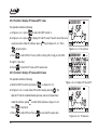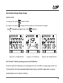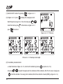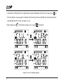
1
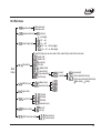
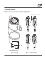
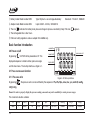
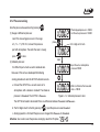
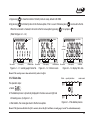
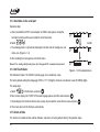
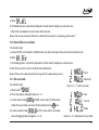
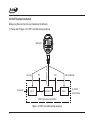
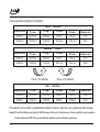
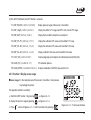
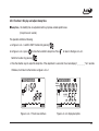
ADT672 DIGITAL PRESSURE CALIBRATOR
ADT 672 DIGITAL PRESSURE CALIBRATOR
User's Manual
[Version No.:1410V13]
Please download the latest version via www.additel.com
Additel Corporation
CONTENTS
WELCOME TO YOUR ADT672……………………………………………………………………………………………………………1
FOR YOUR SAFETY…………………………………………………………………………………………………………………………2
SPECIFICATION………………………………………………………………………………………………………………………………3
DESCRIPTION………………………………………………………………………………………………………………………………6
1.0 Summary…………………………………………………………………………………………………………………………………6
1.1 Basic configuration………………………………………………………………………………………………………………………7
1.2 Terminal introduction……………………………………………………………………………………………………………………8
1.3 Keypad……………………………………………………………………………………………………………………………………8
1.3.1 Definition……………………………………………………………………………………………………………………………8
1.3.2 Data inputting function……………………………………………………………………………………………………………9
1.4 Display introduction………………………………………………………………………………………………………………………9
1.5 Main interface definition………………………………………………………………………………………………………………10
1.6 Menu introduction………………………………………………………………………………………………………………………11
1.6.1 Enter into menu……………………………………………………………………………………………………………………11
1.6.2 Operation steps……………………………………………………………………………………………………………………11
1.6.3 Main menu…………………………………………………………………………………………………………………………12
1.6.4 Calibration menu…………………………………………………………………………………………………………………13
1.7 Power supply introduction………………………………………………………………………………………………………………14
MAIN INTRODUCTION……………………………………………………………………………………………………………………15
2.0 Power on/off………………………………………………………………………………………………………………………………15
2.1 Pressure measure function………………………………………………………………………………………………………………15
Ⅰ
2.1.1 Pressure units………………………………………………………………………………………………………………………15
2.1.2 Pressure zeroing…………………………………………………………………………………………………………………16
2.1.3 Pressure % indication……………………………………………………………………………………………………………17
2.1.4 Peak pressure record…………………………………………………………………………………………………………… 17
2.1.5 Overpressure warning……………………………………………………………………………………………………………18
2.1.6 Resolution adjustment……………………………………………………………………………………………………………18
2.2 Electricital measure function…………………………………………………………………………………………………………19
2.2.1 Switch measure items……………………………………………………………………………………………………………19
2.2.2 Electricital measure………………………………………………………………………………………………………………19
2.2.2.1 Current zeroing………………………………………………………………………………………………………………19
2.2.3 Voltage measure…………………………………………………………………………………………………………………19
2.2.3.1 Voltage zeroing………………………………………………………………………………………………………………19
2.2.4 Temperature measure……………………………………………………………………………………………………………19
2.2.5 Pressure switch measure…………………………………………………………………………………………………………19
2.2.5.1 Operation……………………………………………………………………………………………………………………20
2.2.5.2 Attentions……………………………………………………………………………………………………………………21
2.2.6 Count-down leak test………………………………………………………………………………………………………………21
2.2.7 Switch display resolution…………………………………………………………………………………………………………22
2.3 DC24V output function…………………………………………………………………………………………………………………22
2.3.1 Power on/off DC24V………………………………………………………………………………………………………………22
2.3.2 DC24V Timing output……………………………………………………………………………………………………………23
2.3.3 Protection for short-circuiting and over current…………………………………………………………………………………23
2.4 Backlight function………………………………………………………………………………………………………………………23
2.5 Buzzer function…………………………………………………………………………………………………………………………23
Ⅱ
2.6 Adjust real time function………………………………………………………………………………………………………………24
2.7 RS232 communication function………………………………………………………………………………………………………25
2.7.1 Set RS232 serial port………………………………………………………………………………………………………………25
2.7.2 Submit data automatically…………………………………………………………………………………………………………25
2.7.3 Communication instructions………………………………………………………………………………………………………25
2.7.4 Software……………………………………………………………………………………………………………………………26
DATA LOGGER FUNCTION………………………………………………………………………………………………………………26
3.0 Basic introduction………………………………………………………………………………………………………………………26
3.1 How to operate save menu………………………………………………………………………………………………………………26
3.1.1 See the saved file…………………………………………………………………………………………………………………27
3.1.2 Delete data…………………………………………………………………………………………………………………………28
3.1.3 Send data via serial port…………………………………………………………………………………………………………29
3.1.4 Set file attributes…………………………………………………………………………………………………………………29
3.1.5 Delete all data……………………………………………………………………………………………………………………29
3.1.6 Send all files via serial port………………………………………………………………………………………………………30
3.1.7 Set save mode………………………………………………………………………………………………………………………30
3.1.8 Enter save-file status………………………………………………………………………………………………………………31
3.1.9 Quit save-file status………………………………………………………………………………………………………………31
3.2 Use manual mode………………………………………………………………………………………………………………………32
3.3 Use hour-record function………………………………………………………………………………………………………………32
3.4 Use interval-record function……………………………………………………………………………………………………………33
3.5 Automatic logging with startup………………………………………………………………………………………………………34
III
HART COMMUNICATION FUNCTION…………………………………………………………………………………………………34
4.0 Connect HART…………………………………………………………………………………………………………………………34
4.1 Set inner/external sampling resistance………………………………………………………………………………………………35
4.2 HART communication operation………………………………………………………………………………………………………35
4.3 Display status……………………………………………………………………………………………………………………………36
4.4 Detective linkage………………………………………………………………………………………………………………………36
4.5 HART function introduction……………………………………………………………………………………………………………37
4.5.1 Function 1: Display SENSOR range……………………………………………………………………………………………40
4.5.2 Function 2: Display PV range, switch PV unit, transfer PV range…………………………………………………………… 41
4.5.3 Function 3: Display and adjust damp time………………………………………………………………………………………42
4.5.4 Function 4: display CP value and PV value…………………………………………………………………………………… 43
4.5.5 Function 5: display CP value and AO value……………………………………………………………………………………43
4.5.6 Function 6: Display CA and AO value………………………………………………………………………………………… 44
4.5.7 Function 7: Loop analog current test, AO calibration………………………………………………………………………… 44
4.5.8 Function 8: PV calibration process………………………………………………………………………………………………46
4.5.9 Function 9: Special calibration function……………………………………………………………………………………… 48
CALIBRATION FUNCTION………………………………………………………………………………………………………………49
5.0 Introduction……………………………………………………………………………………………………………………………49
5.1 Calibration condition……………………………………………………………………………………………………………………49
5.2 Calibration menu's operation and content……………………………………………………………………………………………49
5.3 Pressure calibration……………………………………………………………………………………………………………………49
5.4 Cancel pressure calibration……………………………………………………………………………………………………………52
5.5 Current calibration……………………………………………………………………………………………………………………52
IV
5.6 Cancel current calibration………………………………………………………………………………………………………………52
5.7 Voltage calibration………………………………………………………………………………………………………………………52
5.8 Cancel voltage calibration………………………………………………………………………………………………………………52
5.9 Cancel previous pressure zeroing………………………………………………………………………………………………………52
6.0 Accessories………………………………………………………………………………………………………………………………53
APPENDIX I: THE TYPICAL APPLICATION OF ADT672…………………………………………………………………………54
(1) Pressure dial gauge calibration…………………………………………………………………………………………………………54
(2) Pressure switch calibration……………………………………………………………………………………………………………55
(3) Pressure transmitter calibration………………………………………………………………………………………………………56
APPENDIX II: COMMUNICATION PROTOCOL………………………………………………………………………………………57
(1) Instruction format………………………………………………………………………………………………………………………57
(2) Instruction details………………………………………………………………………………………………………………………58
(3) The file's transfer format………………………………………………………………………………………………………………62
(4) Pressure units shortening list……………………………………………………………………………………………………………62
(5) Pressure units info code …………………………………………………………………………………………………………………62
(6) The format of automatically data transfer……………………………………………………………………………………………62
(7) Wrong sequence number explanation…………………………………………………………………………………………………63
(8) HART function's return format…………………………………………………………………………………………………………63
V
Welcome to your ADT672
This detailed user's manual will help you became familiar with the many features of ADT672 Calibrator. The simple step-bystep instructions will quickly guide you through the procedures for using the calibrator and other items needed for accurately
testing and calibrating numerous types of instruments.
All products made by Additel are warranted to be free of defects in workmanship and materials for 1 year from the date of
shipment. No other express warranty is given, and no affirmation of Seller, by words or actions, shall constitute a warranty.
SELLER DISCLAIMS ANY IMPLIED WARRANTIES OF MERCHANTABILITY OR FITNESS FOR ANY PARTICULAR
PURPOSES WHATSOEVER.
If any defect in workmanship or material should develop under conditions of normal use and service within the warranty period,
repairs will be made at no charge to the original purchaser, upon delivery of the product(s) to the factory, shipping charges
prepaid. If inspection by Additel or its authorized representative reveals that the product was damaged by accident, alteration,
misuse, abuse, faulty installation or other cause beyond the control of Additel, this warranty does not apply.
ADDITEL MAKES NO WARRANTY OF ANY KIND WITH REGARD TO THIS MANUAL, INCLUDING, BUT NOT LIMITED
TO, THE IMPLIED WARRANTIES OF MERCHANTABILITY AND FITNESS FOR A PARTICULAR PURPOSE.
Please Notice:The product specifications and other information contained this manual are subject to change without notice.
Additel has made a concerted effort to provide complete and current information for the proper use of the equipment. If there are
questions regarding this manual or the proper use of the equipment, contact Additel at:
1
TEL:(714)998-6899
E-MAIL:[email protected]
FAX:(714)998-6999
WEB: www.additel.com
For your safety
Media & Overpressure:
(-100kPa~400kPa): Non-corrosive and unpolluted gas;
(Higher than 400kPa): media compatible with 316 Stainless Steel.
Overpressure: 120%.
Burst pressure: 300%.
Warning:
Follow all equipment safety procedures.
Do not operate the calibrator around explosive gas, vapor, or dust.
Do not put the battery in the fire or make electricity short circle; Use charger supplied by Additel only.
Never apply more than 32V between mA terminal and common terminal.
Recharge or replace the battery as soon as the battery indicator
appears.
Do not allow water inside the case, please clean and maintain the calibrator periodically.
Do not apply more than 11V voltage to rechargeable jack. Any problem caused by this is not covered under warranty.
To avoid over pressure damages, do not apply pressure that exceeds the limits listed in the pressure specification table.
To avoid mechanically damaging the calibrator, do not apply torque between the pressure fitting and the calibrator case.
Do not disassemble the calibrator. Any problem caused by this is not covered under warranty.
2
Specification
◆Pressure ranges
Gauge Pressure [1]
P/N
V15
GP2
GP5
GP10
GP15
GP30
GP50
GP100
GP300
GP500
GP600
GP1K
GP2K
GP3K
GP5K
GP10K
GP15K
GP20K
GP25K
GP30K
GP36K
GP40K
3
Pressure
Range
(psi)
-15
2
5
10
15
30
50
100
300
500
600
1,000
2,000
3,000
5,000
10,000
15,000
20,000
25,000
30,000
36,000
40,000
Absolute Pressure
Pressure
Range
(bar)
-1.0
0.16
0.35
0.7
1.0
2.0
3.5
7.0
20
35
40
70
140
200
350
700
1,000
1,400
1,600
2,000
2,500
2,800
Media [2]
Accuracy
(% FS)
Burst
Pressure
P/N
G
G
G
G
[3]
G,L
[3]
G,L
G,L
G,L
G,L
G,L
G,L
G,L
G,L
G,L
G,L
G,L
G,L
G,L
G,L
G,L
G,L
G,L
0.025 (0.05)
0.025 (0.05)
0.025 (0.05)
0.025 (0.05)
0.025 (0.05)
0.025 (0.05)
0.025 (0.05)
0.025 (0.05)
0.025 (0.05)
0.025 (0.05)
0.025 (0.05)
0.025 (0.05)
0.025 (0.05)
0.025 (0.05)
0.025 (0.05)
0.025 (0.05)
0.05 (0.1)
0.1
0.1
0.1
0.1
0.1
3X
3X
3X
3X
3X
3X
3X
3X
3X
3X
3X
3X
3X
3X
3X
2X
2X
1.5 X
1.5 X
1.5 X
1.5 X
1.1X
AP5
AP10
AP15
AP30
AP50
AP100
AP300
AP500
AP1K
AP3K
AP5K
Pressure Pressure
Range Media
Range
(bar)
(psi)
5
10
15
30
50
100
300
500
1000
3000
5000
0.35
0.7
1.0
2.0
3.5
7.0
20
35
70
200
350
G
G
G
G
G
G,L
G,L
G,L
G,L
G,L
G,L
Accuracy
Burst
(% FS) Pressure
0.1
0.1
0.1
0.1
0.1
0.05 (0.1)
0.05 (0.1)
0.05 (0.1)
0.05 (0.1)
0.05 (0.1)
0.05 (0.1)
3X
3X
3X
3X
3X
3X
3X
3X
3X
3X
3X
Differential Pressure
P/N
DP1
DP2
DP5
DP10
DP20
DP30
DP50
DP150
DP300
Compound Pressure
Pressure Pressure
Range
Range Media
(inH2O)
(mbar)
1
2
5
10
20
30
50
150
300
2.5
5.0
10
25
50
100
160
350
700
Accuracy
Burst
(% FS) Pressure
0.05[4]
0.05[4]
0.05
0.05
0.05
0.05
0.05
0.025
0.025
G
G
G
G
G
G
G
G
G
100 X
100 X
50 X
20 X
20 X
20 X
3X
3X
3X
P/N
Pressure
Range
(psi)
Pressure
Range
(bar)
Media
Accuracy
(% FS)
Burst
Pressure
CP2
CP5
CP10
CP15
CP30
CP100
CP300
2
5
10
15
-15 to 30
-15 to 100
-15 to 300
0.16
0.35
0.7
1
-1 to 2
-1 to 7
-1 to 20
G
G
G
G
G
G, L
G, L
0.05
0.025(0.05)
0.025(0.05)
0.025(0.05)
0.025(0.05)
0.025(0.05)
0.025(0.05)
3X
3X
3X
3X
3X
3X
3X
Note: [1]. Sealed gauge pressure for above 1000 psi
[2]. G=Gas, L=Liquid
[3]. 0.025% FS for gas media only
[4].* One year accuracy (including yearly stability) except DP1 and DP2 range which is 0.05%FS calibration accuracy and 0.05%FS yearly
stability.
◆Pressure units: mmH2O@4℃, mmHg@0℃, psi, kPa, MPa, Pa, mbar, bar, inH2O@4℃, inHg@0℃ (all units may not be
displayed for all ranges).
◆Overpressure warning: The screen will flash if measuring pressure over 120%FS.
◆Electricity measure and Source Accuracy:
Range
Voltage DC
Accuracy
30.0000V
(0.01%RD + 1.5 mV)
Current DC
30.0000mA
(0.01%RD + 1.5
DC 24V
24V 0.5V max:50mA Protect at: 120mA
Switch [1]
Status OPEN/CLOSED
μA)
4
Note: [1] 1~12V if switch has detective voltage
b. Relative humidity:<95%;
◆Working environment: a. Temperature:(-10~50)℃;
c. Atmosphere pressure :( 86~106)kPa.
◆Storage Temperature: -20℃~70℃.
◆RS232 parameter: Baud rate 1200, 2400, 4800, 9600; Data length is 8 bits; stop bits is 2; address is from 1 to 112.
◆Clock Format:【Y/M/D H:M】the range of year is 2000~2099, 24 hours.
◆Save file capacity: 30 files, 40 records per file.
◆Save file mode: Manual mode and automatic mode (includes hour-record and interval-record "from 1 second to 100 hours").
◆Display: Big segment FSTN LCD with dual lines, grey background and blue backlight.
◆Power supply: Polymer Li-ion rechargeable battery or 10V charger.
◆Charge mode: Special 10V charger (Charge time is 4 hours) .
◆Battery life: 40 hours (The battery icon will flash and buzzer will beep if low power; It will automatically power off prior to any
accuracy degradation).
◆Re-calibration period: One year.
◆Size: Φ120mmx 46mm, total 184mm high.
◆Weight: 0.7kg.
◆Electric connection: I/V/SWITCH measure: standard Φ4mm jack
Recharge: standard Φ4 rechargeable socket
DC24V output: standard Φ4mm jack
RS232: standard DB9 socket
◆Pressure connectors: 1/4” NPT or 1/4” BSP male
Other connections available per request
0.156 inch (Φ4 mm) test hose (for differential pressure)
5
Description
1.0 Summary
The ADT672 is a portable digital pressure calibrator designed to be a rugged calibration tools which has the functions to
calibrate and maintain pressure instruments.
Features:
① High-accuracy pressure measure &wide-range temperature compensation
② Measure function to mA, V and switch
③ HART communication
④ DC24V output
⑤ RS232 port to connect with computer
⑥ Data logging
⑦ Assistant measure function for time and temperature
⑧ A/C or D/C (rechargeable battery)
According to about functions, ADT672 also have some other common functions as below:
① Record the peak pressure
② Indicate % pressure
③ Pressure leak test
④ Trigger switch control
⑤ Data logging
⑥ Communicate with HART pressure transmitter
As a master gauge(or reference gauge), ADT672 digital pressure calibrator is to measure or calibrate pressure instruments
such as pressure transmitters, differential pressure sensors, pressure switches, precision pressure gauges, industry pressure
gauges, sphygmomanometers, pressure transducer and others.
6
1.1 Basic configuration
SW
V
mA
24V
COM
COM
24V
672
DIGITAL PRESSURE CALIBRATOR
672
DIGITAL PRESSURE CALIBRATOR
!
Units
A
0
25
50
75
100
Range:(0~100)kPa
Media:Gas
Accuracy: 0 .02%FS
Overload:200kPa
Current Measurement Range:-30mA~30mA
Voltage Measurement Range:-30V~30V
Accuracy: ( 0.02% rdg+0.003%FS)
Power Output:DC24V@max 50mA
Power Supply:Rechargeable polymer lithium
battery or special adapter
Prod.Date:2009.05
Prod.S/N:0910001
Additel Corporation
Figure 1-1: Configuration view
7
1.2 Terminal introduction
As basic configuration view, Figure 1-1, the ADT672 have 5 standardΦ4mm terminals, from left:
◎SW:Positive terminal for switch measure, red color.
◎V:Positive terminal for voltage measure, red color.
◎mA:Positive terminal for current measure, red color.
◎COM:Communal terminal, black color.
◎24V:Positive terminal for D/C output, red color.
1.3 Keypad Introduction
1.3.1 Definition
Power on/ off.
Units
Switch pressure units.
Pressure to zero (gauge/differential pressure range: -1%FS~1%FS; as for absolute pressure, please refer 2.1.2).
Current/voltage to zero (Range: -0.2%FS~0.2FS).
st
1 function: switch measure type by the sequence of current/voltage/temperature/pressure switch/count-down;
nd
2 function: enter or exit HART linkage status.
st
1 function: Press it to enter into basic function menu or password inputting menu;
nd
2 function: Cancellation (ESC).
8
←
Confirmation ( ).
st
1 function: backlight;
nd
2 function: move decimal digit left(←).
st
1 function: Under the status of file saving, press it once to save a new record or exit;
nd
2 function: Under the status of non-saving, press it to enter into the save file menu;
rd
3 function: Move decimal digit right (→).
st
1 function: Press to send out data via serial port;
nd
2 Adjust the resolution between 5 and 6 digits;
rd
3 function: Move decimal digit up (↑).
st
1 function: Turn on/ off DC24V power;
nd
2 function: Switch the display resolution of current/voltage/temperature;
rd
3 function: move decimal resolution down (↓).
1.3.2 Data inputting function
(←),
(↑),
(→) Move decimal digit left and right
(↓) Increase/decrease the pressure value
Confirm the inputted data (←)
Cancel the inputted data (ESC).
1.4 Display introduction
Battery level: Three bars show the battery level, ADT672 will auto shut off if battery is too low.
Date and time: 【Year/Month/Day Hour: Minute】.
Communication: If this icon is appear, 3 roll bars indicate the ADT672 is sending out the data via RS232.
9
24V: This icon shows if 24V is turned on or off.
Date and Time Communication
Battery level
24V
Pressure units: display the selected pressure units.
HART status: The icon HART shows the communication status, and
Pressure Reading
HART Statas
shows the HART function.
Count-down icon: The cursor starts to rotate when in
HART
Electicity Reading
Count-down Icon
count-down mode.
A
V
0
25
50
75
100
Electricity reading: display the measuring electricity value.
Electricity units: display the measuring current/voltage units.
Status area: indicate % pressure; the % saving files.
Left reading area status area
Electricity Units
the character
24V
Pressure Units
Pressure reading: display the measuring pressure value.
Right reading area
Figure 1-4: Screen introduction
Left reading area: It shows the actual pressure percentage (0%~199%);In data logging, it indicates file number at present.
Right reading area: It shows the actual pressure percentage (0%~199%);
In data logging, it indicates all quantity of saved files.
1.5 Main interface definition
A
The interface of ADT672 includes main interface and menu interface.
Main interface displays all measuring data, as figure 1-5. After ADT672 is
0
25
50
75
100
turned on, the menu interface displays two kinds of status.
Figure 1-5: Main interface
10
(1) The default of main interface is:
Electricital measure mode is current, five digits display
Pressure measure displays five digits
The pressure unit defaults to the pressure unit selected at time of order
Example: As to the calibrator with (0~100) kPa, the default pressure unit is kPa.
(2) When in data logging mode, the default of main interface is:
The electrical measure mode is five digits
Pressure measure displays five digits
The pressure unit defaults to the pressure unit selected at time of order
main interface
main interface
1.6 Menu introduction
press shortly
1.6.1 Enter into menu
Includes main function menu and calibration menu,
refer figure1-6-1.
main menu
press shortly
press longer
input password[2003]
press shortly
1.6.2 Operation steps
calibration menu
press shortly
Enter main menu
Press
11
Select sub-menu
Enter sub-menu
to return to the previous menu or exit.
Figure 1-6-1: How to enter into the menu
1.6.3 Main menu
(peak record)
higher peak value
lower peak value
(set time)
(pressure leak test)
(no trigger)
(off → on)
(on → off)
(off → on → off dual trigger)
(on → off → on dual trigger)
(select trigger type)
(file setting)
Main
menu
(RS232 set up)
select file (View only; user must select a file's number firstly to enter into the next menu)
(check a file)
(delete a file)
(send a file)
(set a file)
(delete all files)
(send all files)
(hour record)
(manual)
(save mode setting)
(interval record after start up)
(automatic)
(start file save)
(start to save automatically after startup
Non-startup,
startup)
(address set up)
(baud rate set up)
(adjust time)
(set 24V time)
(buzzer setting)
(HART resistance setting)
(10minute)
(30minute)
(60minute)
(keep turning on)
(turn off)
(turn on)
(outer resistance)
(inner resistance)
12
1.6.4 Calibration menu
input password(2003)
(pressure calibration)
(pressure calibration executed, cancel calibration)
(current calibration)
calibration menu
(current calibration executed, cancel calibration)
(voltage calibration)
(voltage calibration executed, cancel calibration)
(zeroing before pressure is canceled)
N.B:①
Not a selectable menu item but for viewing only. If enter into the menu, please input the correct
password.
②
The calibration status. 0: Not calibrated, 1: calibrated. Caution: once selected the prior results can't
be restored. The calibration methods of current/voltage are same as pressure calibration.
13
1.7 Power supply introduction
ADT672 have two kinds power source: special 10V adapter and rechargeable battery.
67
2
R
L
a
P
M ng
ed e:( R
ia 0~ ES
:G
C
S
u
as 10
U
0)
V rre
o n
kP R
E
A ltag t M
a
cc e e
C
ur M as
A
LI
P acy ea ure
A
o
cc
B
: ( su m
P we
O
e
r
u
R
ow r
ve ra
0 em nt
A
rlo cy
er Ou .02 en Ra
TO
ad : 0
S tpu % t R ng
P
u t:
r a e
ro
:2 .0 R
d.D ppl DC dg+ ng :-3
00 2
y
%
ate :R 24 0.0 e:- 0m kP F
ec V
a
3
S
0
:2 b h @
3 0 A
00 att ar m % V~ ~3
F
g
0
e
9.0 r e ax
S 3 m
5 y o ab 50 ) 0V A
r s le m
pe po A
c l
P ial ym
ro a e
d.S da r li
t
/N pte hiu
:0 r m
91
00
01
Battery Model:Model number 9702
672
D
IG
IT
A
DIGITAL
PRESSU
RE CAL
IBRATOR
Range:(0~1
00)kP
A
dd
it
el
C
or
po
ra
ti
on
Media:Gas
a
Accuracy:
0
Overload:20.02%FS
Current
0kPa
Measuremen
Voltage
Measu t Range:-30m
Accuracy: rement Range A~30mA
:-30V
( 0.02%
rdg+0.003% ~30V
FS)
Power Outpu
Power Supplt:DC24V@m
y:Rechargeax 50mA
able polym
batter
er
Prod.D
ate:2009.05y or special adaptlithium
er
Prod.S/N:091
0001
Add itel
Cor pora
batte
ry
tion
(1)
(2)
672
DIGITAL PRES
SURE
Range:(0~100)
kPa
Media:Gas
CALIBRATO
R
672
Accuracy: 0
.02%FS
Overload:200kPa
Current Measure
ment
Voltage Measure Range:-30mA~30mA
ment Range:Accuracy: (
30V~30V
0.02% rdg+0.00
3%FS)
Power Output:D
C24V@max
50mA
Power Supply:R
echargeable
polymer lithium
battery
Prod.Date:2009. or special adapter
05
Prod.S/N:091000
1
Addi tel Corp
oratio
Adapter Model: Model number 9814
Figure 1-7-1: recharge
DIGITAL
PRESSU
RE CAL
IBRATOR
Range:(0~1
00)kP
Media:Gas
a
Accuracy:
0
Overload:20.02%FS
Current
0kPa
Measuremen
Voltage
Measu t Range:-30m
Accuracy: rement Range A~30mA
:-30V
( 0.02%
rdg+0.003% ~30V
FS)
Power Outpu
Power Supplt:DC24V@m
y:Rechargeax 50mA
able polym
battery
er
Prod.D
or
ate:2009.05 special adaptlithium
er
Prod.S/N:091
0001
n
Add itel
(3)
Cor pora
tion
(4)
Figure 1-7-2: replace a new battery
14
① Battery model: Model number 9702
Type: Polymer Li-ion rechargeable battery
② Adapter mode: Model number 9814
Input: AC85V~AC245,50Hz/60 Hz
③ The icon
Standards: 7.4V/8.4V, 1600mAh
indicates the battery level, please recharge or replace a new battery timely if the icon
appears.
④ The rechargeable time is four hours.
⑤ Follow all safety regulations and use adapter from Additel only.
Basic function introduction
model No.
2.0 Power on/off
By pressing
pressure unit
lower limit
, ADT672 will be powered on/ off. The
displayed sequence is model number, pressure ranges
higher limit
and the main menu. The startup interface as figure 2-1.
0
2.1 Pressure measure function
2.1.1 Pressure units
By pressing
Units
25
50
75
100
Figure 2-0: Start up interface
, the pressure units can be switched by the sequence of Pa, kPa, Mpa, mbar, bar, psi, mmH2O, mmHg,
inH2O, inHg
Remark: In order to properly display the pressure reading, some units may not be available for certain pressure ranges.
The conversion relation as below:
Pa
1000
15
kPa
1
MPa
0.001
mbar
10
bar
0.01
psi
0.14504
mmH2O
101.974
mmHg
7.50061
inH2O
4.01463
inHg
0.2953
2.1.2 Pressure zeroing
Zero the pressure measurement by pressing
.
1.The displayed pressure is 100.02,
but the actual pressure is 100.00
(1) Gauge or differential pressure:
zero if the measuring pressure is in the range
press
of (-1% ~ 1%) FS. First, connect the pressure
2.First digit start to flash
port with atmosphere. Then after the data is steady,
press
to zero.
input
(2) Absolute pressure:
3.Input the actual atmosphere
pressure 100.00
It is difficult to pull a hard vacuum to absolute zero.
Because of this we have developed the following
zeroing procedure to zero the ADT672 absolute sensors.
a. Connect the ADT672 to a vacuum source or to
4.After confirmation,the measured
data is 100.00
atmosphere, with a reference standard. The reference
pressure is Pstandard. The ADT762 is Pmeasure.
Figure 2-1-2: Absolute pressure to zero
The ADT762 will need to be zeroed if there is a difference between Pstandard and Pmeasure.
b. The first digital starts to flash by pressing
. Input the pressure value Pstandard.
c. Zeroing operation is finished if the pressure is changed from Pmeasure to Pstandard.
Attention: User could cancel the previous zeroing by select the 7th option
.
16
2.1.3 Pressure % indication
The % pressure is indicted by the status area, including:
① Left reading area: Range is (0%~199%)FS; minimum resolution is 1%;
② Right reading area: Range is (0%~199%)FS; minimum resolution is 1%;
③ Status area: Range is (0%~100%)FS; minimum segment is 5%.
When in the non-data logging function, three areas are relative to the measuring pressure P. The calculation formula is below:
Positive pressure (0~PH): %= | P | / PH;
Negative pressure (PL ~0): %=| P | / | PL |;
Compound pressure (PL ~ 0~PH): % = | P | / PH; condition [P ≥ 0];
% = | P | / | PL |; condition [P < 0].
Example: ADT672 w/ (0~2)MPa, status area as figure 2-1-3 if the pressure is 1MPa.
0
25
50
75
100
Figure 2-1-3 % status area
2.1.4 Peak pressure record
The ADT672 self-records the maximum and minimum pressure. The peak value can be checked or cleared by selecting
.The operation steps as following:
(1) In the main interface, the pressure value is P.
(2) Press
17
to enter into Main menu, use
to select
(PEAK), and press
.
(3) Screen shows the maximum and minimum pressure value.
(4) Press
to clear the maximum and minimum pressure, and set P as the current pressure.
(5) Select the suitable pressure unit by pressing
(6) Return to main menu by pressing
Units
.
.
(7) Return to main interface by pressing
, and start to record the maximum pressure and minimum pressure.
(8) If there is any higher or lower peak value, the ADT672 will record it automatically and replace the previous peak value.
(9) After a while, user can repeat step (2), (3) to check the peak value, and repeat the step (6), (7) to exit.
(10) If user needs to record a new peak value, please repeat the steps (1) ~ (7).
2.1.5 Overpressure warning
If a overpressure condition occurs, the buzzer will continuously beep until it is below 120%. Attention: Regardless of the buzzer
on/off condition, it will continue to beep to indicate and over pressure condition.
The warning conditions: (Assumes the pressure is P)
Positive pressure (0~PH): | P | > 1.2 * PH ;
Negative pressure (PL ~0): | P | > 1.2 * | PL |;
Compound pressure (PL ~ 0 ~ PH): | P | > 1.2 * PH, if [P ≥ 0];
| P | > 1.2 * | PL |, if [P < 0].
2.1.6 Resolution adjustment
In the main interface, press
to switch the pressure reading between 5 and 6 digits.
18
2.2 Electrical measure function
2.2.1 Switch measure items
By pressing
, switch the measure items by the sequence of current(mA), voltage(V), environment temperature(℃), switch
, counting-down pressure leak test
.
2.2.2 Electrical measure
Electrical terminal is: ◎mA ◎COM
2.2.2.1 Current zeroing
If it is in the range of (0~ 0.2%FS), please clear the current value to zero by pressing
.
2.2.3 Voltage measure
Electricity terminal is: ◎V
◎COM
2.2.3.1 Voltage zeroing
If it is in the range of (0~ 0.2%FS), please clear the voltage value to zero by pressing
.
2.2.4 Temperature measure
The range is (-20~80)℃ and resolution is 0.1℃. This function is to measure the internal temperature of ADT672.
2.2.5 Pressure switch measure
Electrical terminal is ◎SW ◎COM
Indication icons:
is switching off
;
There are five triggering modes as listed below:
19
is switching on
.
(1) Press
no trigger
to enter into the main menu, select
(SWITCH) by using
and confirm
.
off → on
(2) Screen shows triggering mode menu, please select the suitable mode
by using
and confirm
on → off
.
off → on → off dual trigger
2.2.5.1 Operation
on → off → on dual trigger
The factory default is trigger is off.
(1) No trigger: Monitor switch status and the screen is not in a locked condition.
Figure 2-2-5: Trigger mode selection
(2) Triggering off→on: The screen is locked while the trigger is being
changed. Also, the screen shows the pressure value and switch status.
Press
pressure measure value
to restart a new trigger.
(3) Trigger on→off: The screen is locked while the trigger is changed.
switch status is "off"
Also, the screen shows the pressure value and switch status. Press
switch "on"
to restart a new trigger.
restart
trigger lock the
pressure value
(4) Trigger off→on→off : It is combined by the mode 2 (off→on) and
mode 3 (on→off), it have three steps as following:
st
1 step: The screen is locked after it is changed from "off" to "on",
please unlock the screen by pressing
nd
;
2 step: The screen is locked after the trigger status changed from
"off" → "on"
hold
Figure 2-2-5-1: trigger "off"→"on" process
20
"on" to "off", please unlock the screen by pressing
;
rd
3 step: Go back to 1st step to restart the trigger.
pressure measure value
(5) Triggering on→off→on:It is combined by the mode 3 (on →off)
switch status is "off"
and mode 2 (off →on), it has three steps as below:
1st step: The screen is locked after it is changed from "on" to "off",
please unlock the screen by pressing
hold screen
switch "off"
trigger
lock the pressure value
;
2nd step: The screen is locked after the trigger status changed from
"off" to "on", please unlock the screen by pressing
restart
switch "on"
;
"off" → "on"
rd
3 step: Go back to 1st step to restart the trigger.
2.2.5.2 Attention
unlocked
hold
Figure 2-2-5-2 "off" →"on" →"off" dual triggering
(1) Switch can take D/C (1~12V). Please distinguish the anode and cathode.
(2) At the status of file saving and trigger mode, the ADT672 will save one record automatically at the moment of triggering
and there is no need to press
.
2.2.6 Count-down leak test
This function is to measure the chamber's sealed performance, as below:
(1) Connect the ADT672 with chamber, supply a certain pressure P1.
(2) Please record the second pressure P2 when the set time T is arrived.
(3) According to the margin of P1 - P2, user can confirm if the sealed performance is good.
21
starting pressure P1
Please refer the figure 2-2-6-1 for pressure leak test process. The maximum
time is 99 hours 59 minutes and 59 seconds. The default is 10 seconds. It can
count-down time format
[hour:minute:second]
icon
stop
be set in the main menu, as below:
(1) Please select the
start to count-down
(LEAK) and
(SET).
(2) As figure 2-2-6-2, please input the time as format【hour: minute: second】,
confirm it and return the main interface by pressing
.
process pressure P
count-down time format
[hour:minute:second]
icon
round
2.2.7 Change display resolution
In the main interface, pressure value is switched between 5 digits and 6 digits
by pressing
.
icon
stop
restart
◎COM.
Figure 2-2-6-1: Count-down leak test
2.3.1 Power on/off DC24V
In the main interface, please turn on the DC24V output by pressing
(icon 24V appear). Press
finish pressure P2
starting pressure P1
2.3 DC24V output function
Electricity terminal is ◎24V
count-down to 00:00:00
Hour
Minute
Second
again to close the DC24V (icon 24V
disappears). It is suggested to turn off the DC24V function if it is not used.
first digit flashed to adjust
Figure 2-2-6-2: Count-down time setting
22
2.3.2 DC24V timing output
This function is to protect the unnecessary power consumption if user forgets to close DC24V.
The operation steps as following:
(1) Please select
(output 24V) in the main menu.
(2) As figure 2-3-2 Screen, screen shows the time options of DC24V output.
10minute
30minute
(3) When the selected time is up, the DC24V output is closed automatically.
Remark: under the condition of HART communication, DC24V output function is
60minute
keep turning on
not enabled.
2.3.3 Protection for short-circuiting and over current
Figure 2-3-2 DC24V time setup
ADT672 will turn off and beep automatically if there is any short-circuit or over current(>150mA) between ◎24V and◎COM.
When the alert ceases, DC24V will go back to normal status.
2.4 Backlight function
In the main interface, press
to control the backlight.
2.5 Buzzer function
turn off
User can set up buzzer status as below:
turn on
(1) Select the
(BEEP) in the main menu.
(2) Select on or off to enable or disable the buzzer (see figure 2-5).
23
Figure 2-5 Buzzer option
Remark:
The factory default setting is on, meaning the buzzer is enabled.
Buzzer will beeps under the following conditions :
(1) Correct keystroke beeps once, and the incorrect beeps twice.
(2) Over measure warning.
(3) The correct communication instruction beeps once.
(4) The plugging adapter beeps once.
(5) For short-circle or over current, it continuously beeps.
(6) The sound is once if the ADT672 is turned on or off.
(7) Under the automatic save mode, it beeps once while each record is saved.
(8) For switch status changing, it beeps once.
(9) If the count-down time is up, it beeps once.
2.6 Adjust real time function
The display format is【Year/Month/Day Hour: Minute】, year' s range is 2000~2099, time is 24 hour format.
(1) Select
(RTC) in the main menu.
(2) Input the date and time, see figure 2-6.
cursor beginning position
Figure 2-6: Adjust o'clock
24
2.7 RS232 communication function
2.7.1 Set RS232 serial port
(ADDRESS)
RS232 communication parameter is below:
(BAUD RATE)
① Address range is (1~112), factory default is 1;
Figure 2-7-1-1: Serial port setup
② Baud rate is (1200, 2400, 4800, 9600), factory default is 9600;
③ The data length default is 8; 2 stop bits; no calibration bit; no data flow control.
④ Hardware port: Standard DB9 socket (2 feet is TXD, 3 feet is RXD, 5 feet is GND)
cursor begining position
The setup method for address and baud rate is below:
a. Select the option
(RS232) in the main menu.
Figure 2-7-1-2: adjust address
b. Figure 2-7-1-1 displays the setup menu. User can select the communication address or baud rate.
c. Figure 2-7-1-2 shows the current address and allows for correction.
d. The cursor position is displayed in the current option of baud rate if the baud rate is selected.
2.7.2 Submit data automatically
By pressing
, the communication icon
appears and the ADT672
is sending the measuring data via RS232 port, meanwhile, 3 bars rolls in turn;
by pressing
again, the icon
disappears and the sending is stopped.
Please refer the data sending format in appendix【communication protocols】.
2.7.3 Communication instructions
Please refer the APPENDIX II【communication protocols】for more information.
25
Figure 2-7-1-3: Baud rate option
2.7.4 Software
Please refer to 9500 Additel/Land introduction for more information. Additel/Land is available for free download at
http://www.additel.com/products/Software/.
Data logger function
3.0 Basic introduction
Memory capacity: 30 files, 40 records per file.
Manual mode: Select a file from files (1~30), a record is saved by press
once till the file is full.
Record mode: including hour record, interval record.
◆Hour-record: save one record per every hour.
◆Interval-record: the interval can be set up (1 second ~100 hours).
◆In the record mode, the files are saved according to the set up sequence.
◆The record mode defaults to the previous setting.
◆In the record mode, the keypad is locked. By pressing
to quick save and unlock the keypad.
Save status: left reading area display the current file number;Right reading area displays the saved records; status area
indicate the % of current saved files.
0
25
50
75
100
3.1 How to operate save menu
file No.
(1) Enter into save menu.
Method 1: Select the
Method 2: Press
(FILE) in the basic function menu;
capacity% indication
saved records
Figure 3-0 Saving area
button in the main interface.
26
(2) Select File No. (File operation in menu)
As figure 3-1, select the suitable File No. by using
(Range: 1~30), then press
to confirm.
(3) File menu options
Select the suitable option by using
then press
to confirm.
.
(4) File menu's conten
(SEE) see the saved file
(DELETE) delete the file
(SEND) send out the file
menu
menu option
total 8 items.
(SET) set file attributes (second gauge #, min scale)
(ALL_DELETE) delete all files
(ALL_SEND) Send all files
0
25
50
75
100
(SAVE) Save the file
(SELECT) Select to enter into save mode.
selected file
%file capacity
saved records
Figure 3-1: Select operation files
3.1.1 See the saved file
Operation method:
a. Select
.
b. Screen shows the 1st file's attributes: CODE (second gauge serial No.), factory default is 111111.
27
c. By pressing
to show the 2nd item: SCALE (minimum scale), default is 00.1000.
d. By pressing
it will directly return to the file menu option, if file is vacant. Otherwise, press
When the last record is checked, it will return to the file menu option by pressing
once to add a file No.
. To quit press
.
(Refer the figure 3-1-1-3)
menu
menu
save time
saved
content
A
0
file number
25
50
%file capacity
75
100
saved records
0
file number
Figure 3-1-1-1: second gauge's Serial No.
25
50
%file capacity
75
100
saved records
Figure 3-1-1-2: minimum scale
0
file number
25
50
75
%file capacity
100
saved No.
Figure 3-1-1-3: display file's data
Remark: The saved pressure value and electricity value is 6 digits.
3.1.2 Delete data
file No.
The operation steps:
a. Select
capacity indication
saved records
0
25
50
75
100
0
25
50
75
100
.
b. The deletion process is dynamically displayed in the status area and right and
left reading areas. (As figure 3-1-2)
c. After deletion, the screen goes back to the file menu option.
Figure 3-1-2 File deletion process
Remark: This function will delete the file's contents, but not the file’s attributes (second gauge's serial No. and minimum scale).
28
3.1.3 Send data via the serial port
Operation steps:
a. After connected the ADT672 and computer via RS232 cable, please startup the
0
25
50
75
100
0
25
50
75
100
0
25
50
75
100
serial port receiving software and setup the correct baud rate.
b. Select
.
middle
c. The sending process is dynamically displayed in the two sides of reading area and
status area. (Figure 3-1-3)
d. After sending the screen goes back to the file menu.
Remark: For sending data format, please refer the appendix II: communication protocol.
3.1.4 Set file attributes
Figure 3-1-3 File upload process
File attributes includes: The CODE of second gauge, min scale division value.
The factory default setting: Second gauge CODE is 111111(6 digits), minimum scale division value: 00.1000 (6 digits).
The setup steps:
a. Select
in the file menu and press
.
b. Next, screen displays the "CODE "of the second gauge, please input the code and press
.
c. Screen displays the minimum division value (scale), please input the actual division value and press
.
d. The screen returns to the file menu automatically.
3.1.5 Delete all data
This function is to delete all data and file attributes, and returns to factory default setting. The operation steps:
29
a. Select
.
b. The deletion process is dynamically displayed in the two sides of reading area and status area.
c. After all files are deleted, the screen returns to the file menu.
Remark: The next operation after all the files are deleted will start from the very beginning of file number 1."
3.1.6 Send all files via serial port
The operation steps:
a. Connect ADT672 and computer via RS232 cable, start up the receiving software and set the correct baud rate.
b. Select
.
c. The sending process is dynamically displayed in the two sides of reading area and status area.
d. After all files are sent, it returns to the file menu automatically.
Remark: Please refer sending data format in the appendix II: communication protocol.
hand
3.1.7 Set save mode
automatic
The operation steps:
a. Please select
Figure 3-1-7-1: Select save mode
.
hour
b. The screen displays two options figure 3-1-7-1.
c. If select manual mode
(HAND), screen returns to the file menu.
Under the manual mode, one record will be saved by pressing
d. If select automatic mode
(AUTO), screen returns to the setup
menu with logging mode (see figure 3-1-7-2).
interval
once.
mode
Figure 3-1-7-2: Setup menu of save mode
30
Automatic mode includes hour record and interval record. The cursor points to the current mode.
rd
As figure 3-1-7-2, the 3 item could decide if the automatic mode is operated automatically after start-up.
【0】: After start-up, it will not operate automatically; 【1】: After start-up, it will operate automatically.
e. If select
(HOUR), it returns to the file menu. Then, a record is saved every hour.
f. If select the
(INTERVAL), the screen enters into the interval interface. (The interval range: 1 second ~ 99 hours
99 minutes and 99 seconds). After setup, it returns to the record mode. Then, a record is saved at every interval.
g. If select
(RUN_0), screen displays
item
(RUN_1). Item
is long-term logging.
Remark: If long-term record mode is set, the electricital type and pressure unit cannot be changed.
3.1.8 Enter save-file status
The operation steps:
a. Select
and press
.
Under the manual mode: cursor points to saved file's serial number;
Under the automatic mode: cursor points to the previous file's serial number.
b. Please return to the main interface by pressing
3.1.9 Quit save-file status
Press
31
to quit.
, then ADT672 enter into the save-file status.
is short-term logging,
3.2 Use manual mode
(1) In the main interface, enter into the file menu by pressing
(2) Select the file's serial number(1~30) by using
(3) Select
(4) Select
(5) Select
(6) Select
.
, press
to confirm.
(SET) to set file's attributes (optional).
to save and go to the next menu.
(hand) manual mode. The screen returns to file menu.
to enter the save function. If file is vacant, the cursor will point to the first record. Otherwise, the cursor
points to the last record.
(7) Press
once to save a record in the main interface. Meanwhile, the record in the right reading area will add 1 (1~40).
3.3 Use hour-record function
(1) Press
to enter into the file menu in the main interface.
(2) Select a file's serial number by using
and press
. Under the record mode, the starting position always
points to the previous. Example: The No.20 record of 10th file of last the entry is No.1 file of this time. After entering into
st
the automatic mode, the next new position is 21 record of No.10 file.
(3) If user initialize save position, select
to delete all data. The new position is No.1 record of No.1 file.
(4) Select
to set the file's attributes (optional).
(5) Select
to save and go to the next menu.
32
(6) Select
(7) Select
hour record mode and the screen returns to the file menu.
to startup the save function. The cursor points to the previous saved position.
(8) In the main interface, it saves a record each hour till all 40 records are saved. Then, it will automatically switch to the next
file until all file's storage is full. After that, it will automatically switch to the file No.1 and continue saving.
3.4 Use interval-record function.
(1) Enter into the file menu by pressing
(2) Select a file's serial number by using
in the main interface.
and press
. Under the record mode. The starting position always
points to the previous. Example: The No.20 record of 10th file of the last entry is No.1 file of this time. After entering into the
record mode, the next new position is 21st record of No.10 file.
(3) Select
(4) Select
(5) Select
(6) Select
st
st
to delete all file's data and initialize the save position. The new position is 1 record of 1 file.
to set the file's attributes (optional).
to set the save mode and enter into the next menu.
(interval record mode) to enter into the interval setup interface.
(7) Time format is Hour: Minute: Second (Maximum: 99 hours and 59 minutes and 59 seconds; Minimum: 1 second). After time
is set, please goes back to automatic mode by pressing
(8) Select
and goes back to the file menu option by pressing
.
to startup the save mode. In the main interface, the save file's position keeps same as the previous.
(9) In the main interface, it saves a record each hour till all 40 records are saved. Then, it will automatically switch to the next
file till all file's storage is occupied. After that, it will switch to the file No.1 once again and continue the new saving.
33
3.5 Automatic logging with startup
Set the 3rd item in the record mode menu as
and it goes to the automatic mode after the ADT672 is restarted.
The record status has following features:
(1) Electrical type remains the same as the previous setting(5 digits to display).
(2) Pressure measure displays 5 digits.
(3) Pressure remains the same as the previous setting.
To quit this function:
rd
(1) Set record mode 3 item
.
(2) Or, change save mode to manual mode.
HART communication function
4.0 Connect HART
Before using HART function, the user should know the following:
(1) If the transmitter is HART and its current type.
(2) If the transmitter is supplied by external power or 24V of the ADT672.
(3) If the 250Ω sampling resistance is supplied externally or by the ADT672 (The default is supplied by the ADT672).
34
HART type transmitter has three kinds of connection types (see figure 4-0). It is recommended to use the first type.
1、inner 24V、inner R
2、outer 24V、outer R
3、outer 24V、inner R
+
+ transmitter--
+ transmitter--
-
-
external power
R
+
+ transmitter--
external power
ADT672
24V mA COM
COM 24V mA
ADT672
COM 24V mA
ADT672
* 24V is HART+,mA is HARTFigure 4-0: HART communication wiring diagram
4.1 Set inner/external sampling resistance
(1) Select
(R_IN) in main menu.
(2) As figure 4-1, screen displays the selection menu. (The default is inner resistance)
(3) Press
to select the suitable resistance and return to the main menu.
4.2 HART communication operation
The basic operation steps are:
(1) Select the suitable wiring connection and connect the HART type transmitter.
(2) Press
35
to enter into the HART status and detect the transmitter.
outer resistance
inner resistance
Figure 4-1: select sampling resistance
(3) After the POLLING is successfully, please
to choose HART functions.
(4) Finally, exit HART communication function by pressing
.
4.3 Display status
Icon HART means the current status is HART communication;
Characters
show the current HART's action or implementation.
4.4 Detective linkage
After select the suitable wiring connection, user must enter into the HART function
24V
via the POLLING address linkage.
CP
As well as, user the following points below:
HART
(1) All HART transmitters must follow the POLLING detective instructions.
A
CA
(2) In general, the POLLING address default is "0" (or 1~15).
0
25
50
75
100
(3) After the POLLING address is linked the next HART operation can be processed.
When pressing
to link the transmitter there are the following status in HART area:
(1)
,linking the"0" address.
(2)
,linked the HART, user can process next step.
(3)
,failed to link; however, user can press
Figure 4-4: Linkage interface
to detect the POLLING address from "1" to "15" again.
Suppose the address "8" is linked, the screen shows
; If all addresses fail, it returns to
After the POLLING linked, user can select the nine HART functions by pressing
.
.
36
4.5 HART function introduction
Before using these functions the user should know the following:
(1) Please refer the figure 4-5: HART transmitter working setup map
DIGITAL PRESSURE CALIBRATOR
Units
calibrator
pressure
PV
input
25
50
75
100
PV calibration
zeroing
A
0
AO
account
HART pressure transmitter
Figure 4-5: HART transmitter working setup map
37
AO calibration
input
4 - 20 mA
current loop
(2) The abbreviated words of the ADT672:
PV (Primary variable): The pressure measured by HART transmitter
CP (Calibrator pressure): The pressure measured by calibrator ADT672.
AO (Analog output): The analog output current value set by HART transmitter.
CA (Calibrator amp): The current value measured by calibrator ADT672.
Sensor range: It is the rated pressure for the sensor in transmitter (Over pressure may cause damage).
PV range: The rated range in HART transmitter (Lower limit is corresponding to 4mA, higher limit is corresponding to 20mA).
Actual range: The actual range used in HART transmitter (Lower limit is corresponding to 4mA, higher limit is to 20mA).
(3) HART function's serial number is displaying in the status area, as
is function 1.
(4) As figure 4-5, HART pressure transmitter includes: PV calibration and AO calibration.
PV calibration: The calibration is between PV and AO. Supply the pressure to transmitter. The max/min
pressure is same as the higher/lower limit of transmitter. The actual pressure will have a linear relationship
with the current range (4~20mA) of AO. The PV calibration has same function as the pushbutton
【SPAN】&【ZERO】 calibration in the transmitter.
AO calibration: The calibration is between AO and CA (4~20mA). The transmitter outputs 4mA & 20mA, the CA
value measured by calibrator is sent to the zero register and span register. Then, AO output
value is approximating same as the CA measure value.
Example: The actual range of HART transmitter is 0~16kPa, current output is 4~20mA, 0.1%FS accuracy.
38
The every parameter changing like as following list:
Before
Supplied pressure
PV value
PV range
00.000 kPa
00.010 kPa
00.000 kPa
16.000 kPa
16.020 kPa
16.000 kPa
Calibration
calibration
AO output
CA value
Maximum error
4.001 mA
4.024 mA
0.15%
20.020 mA
20.061 mA
0.38%
process
Supplied pressure
PV value
PV range
AO output
CA value
Maximum error
00.000 kPa
00.010 kPa
00.010 kPa
4.024 mA
4.024 mA
0.15%
16.000 kPa
16.020 kPa
16.020 kPa
20.061 mA
20.061 mA
0.38%
Process 1: PV calibration
After
Process 2: AO calibration
calibration
Supplied pressure
PV value
PV range
AO output
CA value
Maximum error
00.000 kPa
00.010 kPa
00.010 kPa
4.000 mA
4.001 mA
0.006%
16.000 kPa
16.020 kPa
16.020 kPa
20.000mA
20.002mA
0.012%
From above lists, the transmitter is unqualified before calibration. However, it meets the accuracy requirements after calibration.
Remark:PV and AO calibrations are typical for HART instruments. However, AO instruction aren't always available for some transmitters.
For this situation, the ADT672 has a special calibration method to meet the calibration requirements.
39
(5) The ADT672 defined nine HART functions, as below:
F1: dISP_SEnSOr ( DISPLAY_SENSOR )
Display pressure range of the sensor in transmitter.
F2: dISP_rAngE ( DISPLAY_RANGE )
Display transmitter's PV range, switch PV units, transfer PV range.
F3: dISP_dAP ( DISPLAY_DAMP )
Display the transmitter's damp time, and adjust it.
F4: dISP_CP-PV ( DISPLAY_CP-PV )
Display the calibrator's CP value and transmitter's PV value.
F5: dISP_CP-AO ( DISPLAY_CP-AO )
Display the calibrator's CP value and transmitter's AO value
F6: dISP_CA-AO ( DISPLAY_CA-AO )
Display calibrator's CA value and transmitter's AO value.
F7: LOOP_AO ( LOOP AO TEST )
Fixed analog loop current output, AO calibration process(CALIB_AO).
F8: CALIB_PV ( CALIBRATE PV )
PV calibration process.
F9: CALIB_SPEC ( CALIBRATE SPECIAL )
A special calibration of ADT672, please refer 4.5.9.
4.5.1 Function 1: Display sensor range
24V
Sensor range: It is the rated pressure of the sensor in transmitter . Over pressure
may damage the sensor.
HART
The operation method is as follows:
a. Switch to HART function 1 by pressing
b. Display the sensor's range by pressing
c. Press
, as figure 4-5-1-1.
0
25
50
75
100
, as figure 4-5-1-2.
to return to figure 4-5-1-1; switch to function 2 by pressing
.
Figure 4-5-1-1: F1 entrance interface
40
4.5.2 Function 2: Display PV range, switch PV unit, transfer PV range
24V
lower limit
PV range: the rated pressure range in transmitter, lower/higher limit is
unit
HART
corresponding to the 4 mA and 20 mA respectively.
Switch PV unit: mmH2O, inH2O, inHg, mmHg, kgf/cm2, psi, kPa, MPa, Pa,
higher limit
0
mbar, bar.
Transfer PV range: Change PV range (new PV range corresponds to the AO output).
25
50
75
100
Figure 4-5-1-2: Sensor range
The operation method as following:
24V
a. Switch to HART function 2 by pressing
b. As figure 4-5-2-2, press
to show the PV range and it returns to the inter-
face as figure 4-5-2-1 by pressing
c. Press
Units
, as figure 4-5-2-1.
.Switch to function 3 by pressing
HART
.
to switch the PV units.
0
25
50
75
100
d. The steps of transfer range's lower limit:
① Pressing
once, the digit of lower limit will flash once.
② Input the lower limit value, press
Figure 4-5-2-1: F2 entrance
24V
to confirm.
lower limit
unit
③ After the screen shows "_ _ _ _ _ _" for 2 seconds, setup is finished.
HART
e. The steps of transfer range's higher limit:
① Pressing
once, the digit of higher limit will flash once.
② Input the higher limit value, press
to confirm.
③ After the screen shows "_ _ _ _ _ _" for 2 seconds, setup is finished.
41
higher limit
0
25
50
75
100
Figure 4-5-2-1: F2 entrance
4.5.3 Function 3: Display and adjust damp time
Damp time:the stability time. An adjustment will may improve unstable performance.
(Damp time unit: second).
The operation method as following:
a. As figure 4-5-3-1, switch to HART function 3 by pressing
b. As figure 4-5-3-2, press
.
to show the transmitter's damp time. Press
Switch to function 4 by pressing
to return to the figure 4-5-3-1.
.
c. Press the direction keys to adjust the damp time. If the adjustment is successful, the screen displays" _ _ _ _ _ _" for 2 seconds.
Otherwise, it will return to the interface as figure 4-5-3-1.
24V
24V
damp
HART
HART
second
0
25
50
75
100
Figure 4-5-3-1: F3 entrance interface
0
25
50
75
100
Figure 4-5-3-2: display damp time
42
4.5.4 Function 4: display CP value and PV value
24V
The operation method as following:
a. As figure 4-5-4-1, press
b. As figure 4-5-4-2, press
HART
to enter into HART function 4.
to display CP and PV value; The units remain the same
0
as pressure units; Under this interface, press
Units
50
75
100
Figure 4-5-4-1: F4 entrance
to go function 5.
c. Press
25
to go to figure 4-5-4-1; Press
24V
to switch CP & PV units. (mmH2O, mmHg, inH2O, inHg, psi, kPa, MPa,
unit
CP
2
Pa, kgf/cm , mbar, bar)
d. Press
HART
to clear the CP value and PV value to zero.
PV
4.5.5 Function 5: display CP value and AO value
0
25
50
75
100
The operation method as following:
a. Switch to HART function 5 by pressing
Figure 4-5-4-2: display CP value & PV
, as figure 4-5-5-1.
24V
b. As figure 4-5-5-2, screen shows CP and AO value by pressing
; the
digits of CP and AO are determined by pressure and current respectively.
Under this interface, press
Press
c. Press
to switch to the interface as figure 4-5-5-1;
to function 6.
Units
HART
to switch CP unit; Press
0
25
50
75
100
to clear the CP value to zero.
Figure 4-5-5-1: F5 entrance
43
4.5.6 Function 6: Display CA and AO value
Operation method:
a. As figure 4-5-6-1, press
to HART function 6.
b. As figure 4-5-6-2, press
press
to display CA value and AO value. (The units remain unchanged)
to the interface as figure 4-5-6-1; Press
24V
to function 7.
24V
unit
CP
24V
CA
HART
HART
HART
A
A
AO
AO
0
25
50
75
100
Figure 4-5-5-2: display CP & AO
0
25
50
75
100
Figure 4-5-6-1: F6 entrance
0
25
50
75
100
Figure 4-5-6-2: Display CA & AO
4.5.7 Function 7: Fixed loop analog current test, AO calibration
This test is to appoint to the fixed loop current analog output of AO value. The ADT672 can supply analog current of 4 mA,
12 mA and 20 mA. This function can be used to determine the accuracy of a transmitter's output current. If accuracy is
unqualified, please start AO calibration as following:
44
(1) Switch to HART Function 7 by pressing
(2) As figure 4-5-7-2, press
, as figure 4-5-7-1.
24V
to display the analog loop current.
Switch the points among 4 mA, 12 mA, 20 mA by using
Under this interface, press
HART
.
to the interface as figure 4-5-7-1,
0
press
25
50
75
100
to function 8.
Figure 4-5-7-1: F7 Entrance
24V
24V
1st point
24V
3rd point
2nd point
HART
HART
HART
A
CA
A
CA
0
25
50
75
100
A
CA
0
25
50
75
100
0
25
50
75
100
Picture 4-5-7-2: Fixed loop current output
(3) To recalibrate, proceed as below:
a. Under the interface of figure 4-5-7-2, enter into AO calibration by pressing
b. By using
(As picture 4-5-7-3).
to select the sequence of 4mA calibration or 20mA calibration. After The CA value is steady, press
to finish the calibration. Once every point is calibrated, the first line shows the character [END] (as figure 4-5-7-4).
45
c. After calibration, press
to go to the figure 4-5-7-1.
24V
24V
24V
1st point
END
1st point
HART
HART
HART
A
0
25
50
75
100
CA
A
CA
0
25
50
75
100
0
25
50
75
100
Figure 4-5-7-3: AO calibration entrance
24V
24V
24V
2nd point
2nd point
HART
HART
HART
A
CA
0
25
50
75
100
Figure 4-5-8-1: F8 entrance
END
A
CA
0
25
50
75
100
0
25
50
75
100
Figure 4-5-7-4: AO calibration process
4.5.8 Function 8: PV calibration process
The operation method:
a. Switch to HART Function 8 by pressing
b. Press
, as figure 4-5-8-1.
to enter into the calibration menu. Calibration includes lower limit point and higher limit point. Use
46
to prioritize the calibration points.Then supply the pressure to the selected point. After CA value is steady, press
to
finish the calibration. Once every point is calibrated, the first line shows the character [END], the second line displays the
new lower/higher limit of PV range. (As figure 4-5-8-2)
c. After calibration, press
to the interface as figure 4-5-8-1, press
to function 9.
24V
1st point
24V
HART
HART
CP
PV_LL
CA
0
25
50
75
100
0
25
50
75
24V
100
24V
2nd point
2nd point
HART
HART
CP
PV_UL
0
25
50
75
100
0
25
Figure 4-5-8-2: PV calibration process
47
END
1st point
50
75
100
END
4.5.9 Function 9: Special calibration function
For some transmitters, AO calibration instructions cannot be supported. For this situation, ADT672 has a special calibration
method to resolve it. After calibration, the actual pressure range has the linearity relationship with current loop CA (4~20) mA.
This is very useful in application of transmitter with (4~20) mA loop current.
Operation steps as below:
a. As figure 4-5-9-1, press
b. As figure 4-5-9-2, press
to enter HART function 9; press
to enter the detective linkage (see figure 4-4).
to entry calibration menu. The ADT672 self-selects the higher limit point or lower limit point
according to the different pressure supplied by users. After the CP and CA is steady, press
to make screen shows
"_ _ _ _ _ _" in second line. This means the current calibration is finished. If this result is not ideal, it could be re-calibrated.
24V
24V
CP
HART
HART
A
CA
0
25
50
75
100
Figure 4-5-9-1: F9 entrance
0
25
50
75
100
Figure 4-5-9-2: Special calibration interface
48
Calibration function
5.0 Introduction
This function is recalibrate the ADT672. First allow a warm up time of 30 minutes. The ADT 672 should be run on battery power.
Exercise the gauge three times. Now, please start the calibration process. If the ADT672 is in irregular working status, please use
default setting function.
Remark: The calibration must be met the required conditions.
5.1 Calibration condition
(1) Environment:
Temperature: 20℃ 2 ℃; Relative humidity: (45-75) %;
Atmosphere pressure: (86-106) kPa; Power: recommend battery.
(2) Equipments:
Standard voltage source, standard current source, standard pressure source.
5.2 Calibration menu's operation and content
Please refer the [1.6 menu introduction].
5.3 Pressure calibration
Please read the following:
(1) Calibration points will depend on the ADT762 pressure range.
a. Single pressure range: Two calibration points are required. Example: the calibration default point for (0~2)MPa, is 0 MPa
and 2 MPa; the default points for (-100~0)kPa is -100 kPa and 0 kPa. The calibration point for -100 kPa may be
49
may be unattainable. In this case the low pressure calibration point would be as low as possible.
b. Dual pressure range: Three calibration points are required. Example: (-20~20)MPa, the default pressure is -20 kPa,
0 kPa and 20 kPa.
(2) The calibration points are as below:
st
nd
a. 2-point calibration: 1 point is lower limit, 2 point is higher limit.
st
nd
st
nd
Example: (0~100)kPa: 1 point: 0kPa, 2 point: 100kPa; (-100~0)kPa: 1 point: -100kPa, 2 point: 0kPa.
b. 3-point calibration: 1 point is lower limit, 2 is 0, 3 point is higher limit.
st
nd
st
rd
nd
rd
Example: (-20~20)kPa: 1 point: -20kPa, 2 point: 0kPa, 3 point: 20kPa.
(3) During calibration, user can choose the prioritized points. However, it is suggested to use default setting.
Example: ADT672 w/ (0~2) MPa
(1) Press
and press
(2) Select
to enter into passport menu, input the password "2003"
to enter into calibration menu.
and press
standard pressure
to enter into the entrance
st
interface.The【01】of left reading area is 1 calibration point, the user
can select points by using
calibration. (as figure 5-3-1)
.Please press
to start
0
25
50
75
100
calibration point flash
Figure 5-3-1: 1st point entrance
50
st
(3) The first line flashes to remind the user to input the standard pressure of 1 point. (In this example, it is 0.00000 MPa)
st
(4) As figure 5-3-2, screen displays the interface of 1 calibration point. Please supply 0.00000 MPa pressure, and press
st
nd
to finish the 1 point calibration after it is stable. As figure 5-3-3, switch to the 2 point calibration interface.
nd
(5) Under the interface of 2 calibration point, the first line flashes for new standard pressure. In general, it is the default (In this
example, it is 2.00000 MPa), press
for next step.
nd
(6) As figure 5-3-4, screen displays the 2 point calibration interface. Please supply 2.00000 MPa pressure and press
to
nd
finish the 2 point calibration after it is stable. The screen switches to the interface as figure 5-3-1 and the calibration is
finished.
(7) Press
to return to the calibration function menu. The calibration is effective if
standard
pressure
.
standard
pressure
standard pressure
measuring
pressure
0
25
50
75
100
calibration point
Figure 5-3-2: 1st point calibration
51
changed to
0
25
50
75
measuring
pressure
100
calibration point
Figure 5-3-3: 2nd point entrance
0
25
50
75
100
calibration point
Figure 5-3-4: 2nd calibration
5.4 Cancel pressure calibration
(1) Enter into the calibration menu
(2) Select
and press
, the calibration is canceled if screen displays
.
5.5 Current calibration
It is same as the pressure calibration. The default 3-points calibration points are:
① First points: -30mA;
② Second point: 0 mA;
③ Third point: 30mA.
Please note the standard calibration point can be adjusted. The current calibration menu is
.
5.6 Cancel current calibration
(1) Enter into the calibration menu
(2) Select
and press
, the calibration is canceled if screen displays
.
5.7 Voltage calibration
It is same as the current calibration. The default 3-points calibration points are:
① First points: -30V;
② Second point: 0 V;
③ Third point: 30V.
Please note the standard calibration point can be adjusted. The voltage calibration menu is
.
5.8 Cancel voltage calibration
(1) Enter into the calibration menu;
(2) Select
and press
, the calibration is canceled if screen displays
.
5.9 Cancel previous pressure zeroing
(1) Enter into the calibration menu;
(2) Select
and press
.
52
6.0 Accessories
(1) Test cable: Model number 9021
1 set
(2) Warranty
1 pc
(3) User's Manual
1 pc
(4) Adapter: Model number 9814
1 pc
(5) Li-ion Battery: Model number 9702
1 pc
2009.06
0910001
~
53
Appendix I: Typical application of ADT672
(1) Pressure gauge calibration
The operation steps are:
① Connect the pressure gauge and
ADT672 on the pressure pump.
② According to verification regulation,
make ADT672 as a reference
gauge to verify (calibrate) the
pressure gauge.
54
(2) Pressure switch calibration
Operation steps are:
① Connect the pressure switch and
ADT672.
② Press
to select pressure switch
measure. (optional: please select the
triggering type in the menu for pressure
triggering measure)
③ According to sketup map, please connect
the test in terminals cables.
◎SW connect "+" of switch, red color;
◎COM connect "-" of switch, black color.
④ Follow all verification regulations, take
ADT672 as a reference gauge to
calibrate (verify) the pressure switch.
55
(3) Pressure transmitter calibration
Operation steps as following:
① Connect the pressure transmitter and
ADT672 on the pressure test pump.
② Pressing
to select the current
measure item, and press
to
start 24V output. If user needs to control
the output time,please find the related
option in the menu.
③ As right figure, connect the pressure
transmitter and ADT672.
◎24V connect the transmitter +, red color.
◎mA connect the transmitter.
④ Following all verification regulations,
take ADT672 as a reference gauge to
calibrate (verify) the pressure transmitter.
Remark: If user wants to calibrate the HART type pressure transmitter, please enter into the HART status by pressing
.
Please refer the [HART communication function introduction] for further information.
56
Appendix II: Communication protocol
(1) Instruction format
① Data sending format:
A: X: Knnnn: C0: C1: C2: C3: C4+EOS (end of symbol)
A: 1 byte, the instrument's communication address
X: 1 byte, only for W (write) or R (read)
K: 1 byte, M (measure), F (File), O (others)
nnnn: 2-5 bytes, the items operated by K instruction
C0: C1: C2: C3: C4: Parameter, please refer the specified instruction introduction
Eos:0x0 (hex)
② Data returning format:
A: X: Knnnn: C0: C1: C2: C3: C4+ Eos, hereinto:
A: Instrument communication address
X: E or F, E is error info of this frame dates, F is feedback info
Knnnn: It is same as the instruction from upper machine
C0: C1: C2: C3: C4: Feedback data or error info
Eos: 0x0(hex)
③ The communication setting of serial port
A(address):the range is 1~112, factory default setting is 1
Baud rate: 1200、2400、4800 and 9600 is selected, the factory default setting is 9600
Data bit length: 8 bits
Stop bit: 2 bits
Parity digit: N/A
Data flow control: N/A
57
(2) Instruction details
Instructions
A
Address
X
Function Introduction
Correct return value
Knnnn
C0
C1
C2
C3
C4
R
OVER
-
-
-
-
-
Read software version No.
A:F:OVER:version No.+ Eos
R
OTYPE
-
-
-
-
-
Read instrument Mode No.
A:F:OVOK:Mode No. +Eos
R
OCODE
-
-
-
-
-
Read serial number
A:F:OCODE:serial No. OK+ Eos
R
OPRDA
-
-
-
-
-
Read production date
A:F:OPRDA:production date OK+ Eos
W
OBLAC
0 (close)
1 (open)
-
-
-
-
Open/close backlight
A:F:OBLAC:OK+ Eos
W
OBEEP
0 (close)
1 (open)
-
-
-
-
Open/close buzzer
A:F:OBEEP:OK+ Eos
W
OKEY
0 (close)
1 (open)
-
-
-
-
Open/close keypad
A:F:OKEY:OK+ Eos
R
OTIME
-
-
-
-
-
Read clock's time
A:F:OTIME: H: M: S: +Eos
W
OTIME
hour
minute
second
-
-
Set up clock's date
A:F:OTIME:OK+ Eos
R
ODATE
-
-
-
-
Read clock's date
A:F:ODATE:Y:M:D+ Eos
W
ODATE
year
month
day
-
-
Write clock's date
A:F:ODATE:OK+ Eos
R
OBATV
-
-
-
-
-
Read battery's total voltage
A:F:OBATV:total voltage +Eos
R
EXMENU
-
-
-
-
-
Read menu status (0:N/A; 1:Available)
A:F:EXMENU:menu status +Eos
W
EXMENU
-
-
-
-
-
Quit menu status
A:F:EXMENU:OK +Eos
R
OADDR
-
-
-
-
-
Read series port's add(1-121)
A:F:OADDR:address +Eos
W
OADDR
address
-
-
-
-
Set series port's add(1-121)
A:F:OADDR:OK +Eos
W
OBAUD
Baud rate
-
-
-
-
1200,2400,4800,9600
A:F:OBAUD:OK +Eos
W
O24V
0 (close)
1 (open)
-
-
-
-
Open/close 24V output
A:F:O24V:OK +Eos
W
O24VT
1 (10minute)
2 (30minute)
3 (60 minute)
4 (full-open)
-
-
-
-
Set up working time of 24V
A:F:O24V:OK +Eos
Eos
0X00
58
Instructions
A
Correct return value
Knnnn
C0
C1
C2
C3
C4
W
OBIT
P (pressure)
E (electricity)
A (all)
0 (5 digits)
1 (6 digits)
-
-
-
Switch the display resolution
A:F:OBIT:OK +Eos
W
OCONT
0 (close)
1 (open)
-
-
-
-
Set data sending continuously
A:F:OCONT:OK +Eos
R
ORAN
-
-
-
-
-
Read pressure range and type
(0: gauge or absolute, 1: differential )
A:F:ORAN:lower limit: high limit:
pressure unit +Eos
R
MRMD
-
-
-
-
-
Read current pressure value.
A:F:MRMD:P value: unit +Eos
OUINF
-
-
-
-
-
Read the selected pressure unit info code,
refer to App.(5)
A:F:OUINF:unit info code +Eos
-
-
-
Switch pressure unit, refer App. 4
A:F:OUNIT:OK +Eos
-
-
-
Pressure to zero
A:F:OZERO:OK +Eos
R
Eos
W
OUNIT
Shortening Unit
-
W
OZERO
-
-
W
MZERO
P (Pressure)
I (Current)
V (Voltage)
-
-
-
-
Cancel the previous zeroing
A:F:MZERO:OK +Eos
R
OPEAK
-
-
-
-
-
Read peak pressure
A:F:OPEAK:High peak value:Lower
peak value :unit + Eos
W
OPKZE
-
-
-
-
-
Clear peak pressure to present value.
A:F:OPKZE:OK +Eos
W
MRATE
0(low speed)
1(high speed)
-
-
-
-
Adjust pressures responsetime
A:F:MRATE:OK +Eos
W
I (current)
V (voltage)
T (temperature)
MCONE
S (switch)
L (count-down)
H (HART)
-
-
-
-
Switch measure items
A:F:MCONE:OK +Eos
Address
59
Function Introduction
X
0X00
Instructions
A
X
R
Knnnn
MVAL
C0
C1
C2
C3
C4
-
-
-
-
-
Eos
Function Introduction
Correct return value
Read measuring electricity date
Current, voltage, temperature
A:F:MVAL:value: mA /V/℃+Eos
Switch A:F:MVAL:ON/OFF:SW +Eos
Count down A:F:MVAL:START: Start
pressure: END:final pressure: hour:
minute: second +Eos
Return HART function, please refer (8)
W
OVALZ
-
-
-
-
-
Electnicity zeroing is only effective for I &V
A:F:OVALZ:OK +Eos
R
OTEMP
-
-
-
-
-
Read environment TEMP.
A:F:OTEMP:temperature: ℃+Eos
-
-
-
-
Set up pressure switch's working type.
A:F:MSWI:OK +Eos
Unlock the trigger switch
A:F:MSTIO:OK +Eos
Read switch's trigger value
A:F:RSWI:pressure value: unit: switch
on/off status: trigger symbol +Eos
W
MSWI
W
MSTIO
0 (no trigger)
1 (off→on)
2 (on→off)
3(off→on→off)
4(on→off→on)
-
-
-
-
-
R
RSWI
-
-
-
-
-
W
MLEKT
hour
minute
second
-
-
Set up leak hunting time
A:F:MLEKT:OK +Eos
-
-
-
-
Switch HART function item 0-8
A:F:HARTSW:OK +Eos
Address
W
0-8
HARTSW
HART function
0X00
W
FIXAO
4-20mA
current value
-
-
-
-
Set transmitter outputting the fixed current.
It is canceled if current is 0.
A:F:FIXAO:OK +Eos
W
AOCAIB
0(4mA)
1(20mA)
Current
calibration
-
-
-
Calibrate the transmitter's loop current
A:F:AOCAIB:OK +Eos
W
PVCAIB
0(ZERO)
1(SPAN)
-
-
-
-
Calibrate the high and lower limit of
transmitter
A:F:PVCAIB:OK +Eos
A:F:PVTRAN:OK +Eos
W
PVTRAN
High limit
Lower limit
Unit
-
-
Transfer transmitter range
W
DAMPING
Damp value
-
-
-
-
Set transmitter damp value
A:F:DAMPING:OK +Eos
R
HARTSTA
-
-
-
-
-
Read HART order implement status
A:F:HARTSTA:Status(0/1)+Eos
60
Instructions
A
Address
Correct return value
Knnnn
C0
C1
C2
C3
C4
W
HARTCMD
HART
sending frame
-
-
-
-
Set up HART’s command in random
HART return frame
W
FMODE
0(manual)
1(auto)
0(hour)
1(interval)
0(short)
1(long)
-
-
Set up file storage mode
A:F:FMODE:OK +Eos
R
FMODE
-
-
-
-
-
Read save mode
A:F:FMODE: manual/automatic: hour :
interval: interval time: file (Y/N) +Eos
Eos
W
FTIME
hour
minute
second
-
-
Set the time of hour-record
A:F:FTIME:OK +Eos
W
FSTART
1~30
-
-
-
-
Appoint a file and enter save status
A:F:FSTART:OK +Eos
W
FSAVE
-
-
-
-
-
Save a new record
A:F:FSAVE:OK +Eos
W
R
FSTOP
-
-
-
-
-
Quit save status
A:F:FSTOP:OK +Eos
FRDO
File number
-
-
-
-
Read a file's data
Return format refer to (1)
W
W
FDELO
File number
-
-
-
-
Delete a file
A:F:FDELO:OK +Eos
FDELA
-
-
-
-
-
Delete all files
A:F:FDELA:OK +Eos
W
OCPS
-
-
-
-
-
Entrance instruction of pressure calibration
A:F:OCPS:OK +Eos
W
OCP
Standard P at
calibration point
-
-
-
Input the pressure value and relative
calibration point, for calibration
A:F:OCP:OK +Eos
-
-
-
-
Quit pressure calibration
A:F:OCPOK:OK +Eos
W
61
Function Introduction
X
Z(zero)
M(middle)
F(full)
OCPOK 1(save)0(cancel)
0X00
W
OCIS
-
-
-
-
-
Entrance instruction for current calibration
A:F:OCIS:OK +Eos
W
OCI
1/ 2 /3
Standard I at
calibration point
-
-
-
Input the current value and relative
calibration point, for calibration
A:F:OCI:OK +Eos
W
OCIOK
1(save)0(cancel)
-
-
-
-
Quit current calibration
A:F:OCIOK:OK +Eos
W
OCVS
-
-
-
-
-
Entrance instruction for voltage calibration
A:F:OCVS:OK +Eos
W
OCV
1/ 2 /3
Standard V at
calibration point
-
-
-
Input the voltage value and relative
calibration point, for calibration
A:F:OCV:OK +Eos
A:F:OCVOK:OK +Eos
W
OCVOK 1(save)0(cancel)
-
-
-
-
Quit voltage calibration
W
OFALT
-
-
-
-
Cancel calibration parameter and calculation
A:F:OFALT:OK +Eos
for P/ I/ V, go back to factory default setting.
W
OTAG
Note No.(1~10) Note content
50 bytes longest
-
-
-
Write note's information
A:F:OTAG:OK +Eos
R
OTAG
Note No.(1~10)
-
-
-
Read note's information
A:F:OTAG:Note #:Note info +Eos
P/ I /V
-
(3) The file's transfer format
Filename: F01
/* File name */
Number: 111111
/* the serial No. of second gauge */
Minscale: 001.000
/* Minimum scale value */
Datesum: 01
/* the saved points in file */
No.01 06/07/03 10:29:53
/* Point number, save date, time */
0.0108MPA
/* Pressure measure value */
-0.0000mA
/* Electricity measure value */
(4) Pressure units shortening list
Shortening
Standard
H2O
mmH2O
HG
mmHg
PSI
psi
MBAR
mbar
BAR
bar
PA
Pa
KPA
kPa
MPA
MPa
(5) Pressure units info code
Info code use 1 byte.1: this pressure unit is available; 0: N/A
HG
H2O
PSI
BAR
MBAR
MPA
MSB
KPA
PA
LSB
(6) The format of automatically data sending
The format length is 32 bytes, and add the Eos 0x0 at the end.
Example: *P 0.0364 MPA *I -0.0001
mA
*P 0.0367 MPA *V -0.0158
V
*P 0.0374 MPA *T 32.19
℃
*P 0.0375 MPA *S 000000.0
0
*P 0.0397 MPA *L 10:00:05
62
(7) Wrong sequence number explanation
1000
1001
1004
1005
1007
1016
1017
1018
1019
1020
1021
1023
1024
1025
1026
1027
1029
1030
Accept outflow from buffer.
The instruction is being protected now.
Digital character string have non-permitted characters.
Pressure unit is irregular.
Parameter is wrong.
The data can't meet the zeroing requirements.
The parameter quantities is not enough.
Unsupported instruction.
The format of operation password is wrong.
r/w Symbol is wrong.
The file number is out of range.
The shortening pressure unit is wrong.
This pressure unit can't use.
The series address is out of range 1-112.
Baud rate is wrong.
The time parameter of 24V open/close is wrong.
Parameter is too long.
Not contact with HART yet.
(8) HART function's return format
Function 0: Linked the POLLING successfully
Address: F: MVAL: DEVICE: Manufacture: Equipment type: Equipment ID
Example: 001: F: MVAL: DEVICE: Endress & Hauser: Cerabar M: W ["Q
63
Function 1: Display the sensor ranges used by HART transmitter.
Address: F: MVAL: SENSOR_RANGE: Lower limit of sensor: Higher limit of sensor: Pressure unit
Switch to function 1,it is returned but not enter into the interface yet (example 1); oppositely, it returns after interface
displayed (example 2)
Example 1: 001: F: MVAL: SENSOR_RANGE: 0.00000000: 0.00000000: NC
Example 2: 001: F: MVAL: SENSOR_RANGE: -40.0000000: 40.0000000: KPA
Function 2: Display and transfer the PV range of transmitter, switch PV units
Address: F: MVAL: PV_RANGE: Lower limit of PV range: Higher limit of PV range: Pressure unit
Switch to function 2, it returned but not enter in the PV interface yet (example 1); oppositely, it returns after interface
displayed (example 2)
Example------001: F: MVAL: PV_RANGE: 0.00000000: 0.00000000: NC
Example------001: F: MVAL: PV_RANGE: -0.01506382: -0.02472788: KPA
Function 3: Display and adjust transmitter's damp value
Address: F: MVAL: DAMPING: damp value: Unit (second)
Example------001: F: MVAL: DAMPING: 1.000: s
Function 4: Simultaneously display the pressure value measured by calibrator and transmitter.
Address: F: MVAL: PV/MP_VALUE: pressure measured by transmitter:Unit:pressure measured by calibrator:Unit
Switch to function 4, it returned but not enter in the PV/MP interface (example 1); oppositely, it returns after interface
displayed (example 2)
Example 1------001: F: MVAL: PV/MP_VALUE: 0.00000: NC: 0.01414: KPA
Example 2------001: F: MVAL: PV/MP_VALUE: 0.00973: KPA: 0.00984: KPA
64
Function 5: Simultaneously display the pressure value measured by calibrator and the current value measured by transmitter
Address:F:MVAL:AO/MP_VALUE:Current value measured by transmitter:Unit:pressure value measured by calibrator:Unit
Switch to function 5, it returned but not enter in the AO/MP interface yet (example 1); oppositely, it returns after interface
displayed (example 2)
Example 1------001: F: MVAL: AO/MP_VALUE: 0.00000: MA: 0.01088: KPA
Example 1------001: F: MVAL: AO/MP_VALUE: 4.00000: MA: 0.01012: KPA
Function 6: Simultaneously display the both current value measured by calibrator and transmitter.
Address: F: MVAL: AO/MI_VALUE:Current value measured by transmitter:unit:current value measured by calibrator:unit
Example: 001: F: MVAL: AO/MI_VALUE: 4.00000: MA 4.00265: MA
Function 7: Appoint to the fixed current output from transmitter; calibrate the current output from transmitter
Address: F: MVAL: FIXAO/MI_VALUE: Current output from transmitter: unit: current value measured by calibrator: unit
Switch to function 7, it returned but not enter in the FIXAO/MI_VALUE yet (example 1); oppositely, it returns after it is
displayed (example 2)
Example1: 001: F: MVAL: FIXAO/MI_VALUE: 0.00000: MA 4.00255: MA
Example2: 001: F: MVAL: FIXAO/MI_VALUE: 4.00000: MA 4.00249: MA
Function 8: Calibrate the PV ranges of transmitter
Address: F: MVAL: MP_VALUE: The pressure value measured by calibrator: unit
Example: 001: F: MVAL: MP_VALUE: 0.01025: KPA
Function 9: Special calibration mode
Address: F: MVAL: MP/MI_VALUE: Pressure value measured by calibrator: current value measured by calibrator: unit
Example: 001: F: MVAL: MP/MI_VALUE: 0.00346: KPA: 4.00242: MA
65
Additel Corporation
22865 Savi Ranch Parkway Ste F
Yorba Linda, CA 92887, USA
Phone: 714-998-6899
Fax: 714-998-6999
Email: [email protected]
website: www.additel.com