1
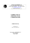
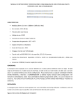
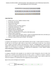
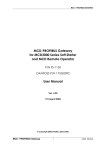
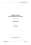
DTS-12
SDI Turbidity Sensor
User Manual
1.800.548.4264
www.ftshydrology.com
700-DTS-12 – Rev. 20, 08 Jan 2014
Contact information
FTS
1065 Henry Eng Place
Victoria, B.C., V9B 6B2
CANADA
www.ftshydrology.com
Toll-free
Local
Technical support
1-800-548-4264
250-478-5561
support.ftshydrology.com
Revision History
Date
Person
Description
27 Jan 2012
RG
Update for DTS-12A and format to current standard
10 Dec 2012
PB
Correction made to BES equation on pg 12
16 May 2013
CV
Clarification improvements and added appendices
13 June 2013
CV
Updated cable connect/disconnect instructions and deployment guide
12 July 2013
CV
Updated deployment guide drawings
08 Jan 2013
CV
Corrected typo in DTS request data response
Table of contents
Contact information ........................................................................................................................................... ii
Chapter 1
Operation ................................................................................................................................... 5
1.1 General description ...........................................................................................................................................................6
1.2 Unpacking .............................................................................................................................................................................7
1.3 Installation .............................................................................................................................................................................7
1.4 SDI Connection ....................................................................................................................................................................9
1.5 Operation ............................................................................................................................................................................ 11
1.6 Address configuration ................................................................................................................................................... 12
1.7 Calibration and maintenance ..................................................................................................................................... 12
1.8 Replacement Parts .......................................................................................................................................................... 14
Chapter 2
SDI Commands ........................................................................................................................ 15
2.1 Notation for SDI commands ........................................................................................................................................ 16
2.2 Commands recognized by the DTS-12 ................................................................................................................... 16
2.3 General SDI commands ................................................................................................................................................. 18
2.4 SDI measurement and data commands ................................................................................................................. 18
2.5 Extended command set ................................................................................................................................................ 21
Chapter 3
Technical specifications ........................................................................................................ 22
Appendix A
Commands recognized by the DTS-12 (historical) .......................................................................................................... 25
Chapter 1
Operation
Chapter contents
1.1
1.2
1.3
1.4
1.5
1.6
1.7
1.8
General description ........................................................................................................................................................... 6
Unpacking ............................................................................................................................................................................. 7
Installation ............................................................................................................................................................................ 7
SDI Connection ................................................................................................................................................................... 9
1.4.1
SDI-12 connectorized cable
1.4.1.1
Cable connection
1.4.1.2
Cable disconnection
Operation ........................................................................................................................................................................... 11
1.5.1
Startup Operation of Turbidity Sensor
1.5.2
Turbidity measurement
1.5.3
DTS-12 calculations
Address configuration ................................................................................................................................................... 12
Calibration and maintenance ..................................................................................................................................... 12
Replacement Parts .......................................................................................................................................................... 14
DTS-12 User Manual
1.1
Chapter 1 Operation
General description
The FTS DTS-12 Turbidity Sensor (DTS-12) measures turbidity and suspended solids concentrations in liquids. The
method used is called optical back scatter and employs a detector at 90 degrees to the incident light beam. In
practice what this means is that light is emitted into a liquid medium and any amount of reflection detected from
suspended matter is a measure of the turbidity of the medium. To achieve this result the latest in micro power,
solid state, and infrared laser technology is used. The laser light output is modulated and synchronously detected
so that any effects from ambient light conditions are minimized. The measurement range of the DTS-12 is 0 to
1500 NTU, making it ideal for stream and river applications.
The DTS-12 has a built in wiper that is useful for reducing the effects of silt build up and biological fouling of the
sensor optics. The DTS-12 is factory programmed with turbidity calibration coefficients. The micro controller
applies these coefficients to the raw measurement data and computes mean, median, maximum, minimum,
variance, and BES (Best Easy Systematic estimator). All turbidity data is returned in NTUs (Nephelometric Turbidity
Units).
All control and measurement functions of the DTS-12 are initiated by sending it a SDI-12 command. SDI-12 stands
for Serial Data Interface at 1200 baud. It is a standardized protocol that defines how microprocessor based sensors
can communicate with data loggers.
Figure 1-1: DTS-12 Turbidity Sensor
page 6
DTS-12 User Manual
1.2
Chapter 1 Operation
Unpacking
You should have received the following materials with each DTS-12 sensor:
1.
DTS-12 Turbidity Sensor complete with 25’ (or user specification) of polyurethane cable.
2.
Spare wiper blade.
3.
DTS-12 SDI Turbidity Sensor Operating Manual.
1.3
Installation
In most cases the best deployment for a turbidity sensor is inside protective tubing (typically PVC pipe) that is
placed in the river and fastened securely to the shore by various means (concrete pillars, metal stakes etc.).
Figure 1-2 shows such an installation. If in doubt consult FTS regarding the best deployment options for your site.
The DTS-12 must be oriented such that the optical window has at least 4 inches axial end clearance and 2 inches
radial side clearance from any physical objects (e.g. the river bottom). The sensor should be located in an area that
is representative of the water to be measured.
Figure 1-2: Typical DTS-12 installation
page 7
DTS-12 User Manual
Chapter 1 Operation
To aid in installation, FTS can supply a DTS-12 sensor deployment guide. This “deployment guide” can be used in
conjunction with the user supplied and constructed 4-inch ID deployment tube. The deployment guide can be slid
down the inside of the protective tubing (typically schedule 40 Aluminum or PVC pipe) that is placed in the river.
Examples are shown in the figures below.
Figure 1-3: DTS-12 deployment guide (diagram)
Figure 1-4: ABS Deployment Guide installed on a DTS-12
page 8
DTS-12 User Manual
Chapter 1 Operation
Figure 1-5: Typical DTS-12 deployment tube and deployment guide combination
1.4
SDI Connection
The SDI cable (nominally 25 feet long) may be connected to the DTS-12 by waterproof gland or underwater
connector. Normally the free end of the cable is shipped with a length of the polyurethane jacket removed to
expose the three 20 AWG conductors. This allows maximum flexibility when connecting to a data logger that uses
a terminal strip.
The SDI cable may be optionally terminated with a 3-pin military connector for connection to similar connector on
1
the data logger. Cable wire colour coding and FTS standard connector pinouts are shown in the table and
diagram below:
1
Wire colour
Pin
Function
Red
A
+12 V DC power supply
White
B
Data
Black
C
Ground
1
Waterproof military-style bayonet connector 851-06JC8-3AP50; FTS part number 520-83AP; compatible with FTS
Axiom dataloggers.
page 9
DTS-12 User Manual
Chapter 1 Operation
1.4.1 SDI-12 connectorized cable
The DTS-12 can be ordered with fixed length connectorized cables (60 and 100 ft.) that allow for quick disconnect
and re-connection. This watertight connection is submersible and permits easy sensor removal from a field
installation without removing the cable. In complex installations or on installations with long cable runs this is a
very desirable attribute.
A thin film of dielectric grease is placed on the End Cap Flange during connection at the factory. This facilitates
the operation of the connection and should be reapplied as needed to ensure the connection can be unplugged.
If doing so, ensure that the grease is kept out of contact with the electrical prongs and receptacles to avoid a poor
electrical connection.
Warning: Because of the tight fit of this connection, inexperienced users tend to twist and bend the connection
when connecting or disconnecting the cable. This inappropriate handling WILL damage the female
receptacles inside the Cable Connection.
See “How to connect and disconnect the DTS-12 turbidity sensor waterproof connectorized cable” video on the FTS
web page for proper procedure. http://www.ftsenvironmental.com/video/
1.4.1.1
Cable connection
Figure 1-6: Cable connection details
page 10
DTS-12 User Manual
1.4.1.2
Chapter 1 Operation
Cable disconnection
After unscrewing the locking collar slide it up the cable out of your way. Firmly grip the probe and cable
connection as outlined below and rotate and pull the connection apart. Ensure you do not bend or twist the cable
connection.
Figure 1-7: Cable disconnection details
Caution:
The female receptacles inside the cable connection are susceptible to damage if the connection is bent or twisted.
These actions can splay out the female connections to the point that electrical contact with the male prongs
becomes intermittent. In addition, one of the male prongs on the DTS-12 end cap has a larger diameter than the
other two. This larger diameter prong must be aligned with the two reference nipples on the cable connector (as
shown in the connection photos above) to ensure that the prongs are inserted into the correct receptacles.
Forcing insertion into the wrong position will permanently damage the connection. Aggressive twisting can also
result in bending and breaking prongs.
Do’s and Don’ts:
1.
Do use clean dielectric grease to lubricate the DTS-12 End Cap
2.
Do keep prongs and receptacles free from grease
3.
Do keep the End Cap Prongs and Cable Connection Receptacles dry
4.
Do not disconnect the cable under water
5.
Do not leave an unconnected cable connection underwater
6.
Do not bend or twist the cable connection during connection or disconnection
1.5
Operation
1.5.1 Startup Operation of Turbidity Sensor
When power is first applied to the DTS-12 a wipe cycle will occur. This is a normal part of the sensor initialization.
When the wiper returns to its normal parked position the DTS-12 is ready to accept SDI commands.
1.5.2 Turbidity measurement
A measurement is initiated when the logger sends an appropriate SDI command to the DTS-12. When this
happens, the DTS-12 will execute a measurement cycle consisting of the following steps:
page 11
DTS-12 User Manual
Chapter 1 Operation
1.
Power up the sensor head.
2.
Calibrate the analog to digital converter circuitry.
3.
Read the water temperature
4.
Do a wipe (if the command calls for a wipe) if the water temperature is not too low
5.
Acquire 100 samples at 20 samples per second.
6.
Perform statistical calculations as required.
After about 10 or 20 seconds (this time is dependent on the type of measurement requested) the sensor will
respond with a service request and the logger will retrieve the measurement by issuing a SDI “D0” command. The
wiper may be activated explicitly as a single operation or implicitly as the first part of a measurement command.
See the section on SDI commands for the individual command descriptions.
Note: A wipe operation will add an additional 5 seconds to the measurement operation.
1.5.3 DTS-12 calculations
The statistical calculations performed by the DTS-12 on the 100 samples are shown below:
̅
mean(average)
variance
∑(
∑
)
median
S
Where
1.6
is measurement ‘I’ in the sorted list
Address configuration
The DTS-12 is shipped with default address 0 (unless shipped as part of an integrated FTS system). Refer to section
2.3.3 Change Address for instructions on setting the sensor’s address.
1.7
Calibration and maintenance
The only field maintenance required by the DTS-12 is a periodic check of the wiper for deterioration or fouling
with biological or other material. If fouling is detected and the wiper blade is in otherwise good condition it may
be cleaned and re-used. Use a soft lint free cloth or wipe with Methyl or Ethyl alcohol, soaps or detergents to clean
the, wiper, optic surface and body of the probe. You may also use a soft toothbrush to help remove the material.
Care must be taken not to scratch the window as this may affect the sensor calibration. Do not use harsh or
page 12
DTS-12 User Manual
Chapter 1 Operation
abrasive cleansers or petroleum products. If the wiper blade edge appears ragged or uneven then the wiper
assembly should be replaced. Each DTS-12 is shipped with a spare piece of wiper material (698-DTS12-WIPER)
packaged in a small zip-lock bag attached to the cable. These can be changed as shown below. Complete
replacement wiper arm assemblies may also be purchased from FTS (part # DTS12-WIPER). The complete assembly
can be changed by loosening the thumbscrew to remove the old wiper assembly and replacing it with the new
wiper assembly.
If tools and a work area are available then replacing the wiper blade is an option. To replace the wiper blade refer
to Figure 1-8 and perform the following operations:
1.
Remove the wiper assembly consisting of the wiper arm and wiper blade by undoing the wiper arm
thumbscrew with your fingers. To reduce unnecessary stress on the wiper drive system hold the wiper
arm while turning the thumbscrew counter clockwise
2.
On older models remove the split pin from the wiper arm by tapping it out with a punch of the same
diameter. The current design incorporates a slot with a circular opening at one end that allows the wiper
material to be maneuvered out of, or into the slot.
3.
In both cases slide the old blade off the wiper arm.
4.
Reassemble using a fresh wiper blade following the previous steps in reverse order.
Wiper Blade
Wiper Armature
M3 X 8 Thumbscrew
Figure 1-8: DTS-12 Wiper Arm Detail
page 13
DTS-12 User Manual
1.8
Chapter 1 Operation
Replacement Parts
If replacement parts are required, the entire wiper assembly shown in Figure 1-8 (p. 13) can be ordered from FTS
by specifying part number DTS12-WIPER. If individual components are required, specify part number according to
the table below.
FTS Part Number
Description
DTS12-WIPER
Wiper and Armature assembly
993-WIPER-ARM
Wiper Armature
698-DTS12-WIPER
Wiper Blade
610-M3X8-TMB
M3 x 8 Thumbscrew
page 14
Chapter 2
SDI Commands
Chapter contents
2.1
2.2
2.3
2.4
2.5
Notation for SDI commands........................................................................................................................................ 16
Commands recognized by the DTS-12 ................................................................................................................... 16
General SDI commands ................................................................................................................................................ 18
2.3.1
Address Query
2.3.2
Acknowledge Active
2.3.3
Change Address
2.3.4
Send Identification
SDI measurement and data commands ................................................................................................................. 18
2.4.1
Start Measurement
2.4.2
Start Concurrent Measurement
2.4.3
Request Data
2.4.4
Continuous Measurement
2.4.5
Start Verification
Extended command set ................................................................................................................................................ 21
2.5.1
Enable Median in M command
2.5.2
Enable Mean (average) in M command
2.5.3
Report M command status
2.5.4
Set low temperature wipe cutoff value
2.5.5
Enable low temperature wipe cutoff
2.5.6
Disable low temperature wipe cutoff
2.5.7
Report low temperature wipe cutoff status
DTS-12 User Manual
2.1
Chapter 2 SDI Commands
Notation for SDI commands
In the end, SDI commands are strings of characters sent to the SDI device. The format of those strings is important,
of course, and to specify the format of SDI commands we use different typefaces. All commands (and the replies
from the device) are represented in a monospaced font. Different parts of a command are represented with variants
on this text format.
Item
Explanation
Text representation
Command literal
Part of a command that must be
reproduced literally as it appears
X
Command
parameter
Part of a command that must be filled in
with an appropriate value
data
Address part of
command
First character of command (except
Address Query). Valid values 0-9, a-z, A-Z.
a
2.2
Commands recognized by the DTS-12
The table below provides a quick reference to the commands recognized by the DTS-12. For details on these
commands, see the following sections.
IMPORTANT ! The commands below are for DTS-12 version 20 and up. To determine your version number
perform an Identification Command and look at the VX field. Identification response = aCN#FTS----DTS12—VXSN#. See Appendix A for older command sets.
Command name
Command code
Address Query
?!
Notes
Acknowledge Active
a!
Change Address
aAb!
Send Identification
aI!
Resp = aCN#FTS----DTS12—VX-SN#
a = address
CN# = SDI-12 compatibility number
FTS = manufacturer identifier
DTS12 = sensor type
VX = firmware version number
SN# = serial number
Start Measurement (general)
aM!, aMC!,
aMn!, aMCn!
C following a command requests a CRC code in
the data return (D command)
b is the new address, a single alphanumeric
character in the range 0-9, a-z, A-Z
n is a digit between 1 and 9
Start Concurrent Measurement
(general)
aC!, aCC!,
aCn!, aCCn!
C following a command requests a CRC code in
the data return (D command)
n is a digit between 1 and 9
Start Measurement:
Median Mode (factory default)=
Temperature, Median Turbidity,
Variance of the Mean, Wipe Status*
aM! , aMC!,
aM0!,aM0C!
aC!, aCC!
Causes a wipe before the measurement
Median mode returns 4 data points.
page 16
DTS-12 User Manual
Chapter 2 SDI Commands
Command name
Command code
Notes
Start Measurement:
Mean (average) Mode =
Temperature, Mean Turbidity,
Variance of the Mean
aM! , aMC!,
aM0!,aM0C!
aC!, aCC!
No wipe before measurement
Mean (average) mode returns 3 data points.
Start Measurement: Mean, Variance,
Median, BES, Min, Max, Temperature
aM1!, aMC1!,
aC1!, aCC1!
No wipe
Start Measurement: Mean, Variance,
Median, BES, Min, Max,
Temperature, wipe status*
aM2!, aMC2!,
aC2!, aCC2!
Wipe before measurement
Start Measurement: Single turbidity
measurement
aM3!, aMC3!,
aC3!, aCC3!
No wipe
Reserved for factory use
aM4! , aMC4!,
aC4!, aCC4!
Not used
aM5!, aMC5!,
aC5!, aCC5!
Not used
aM6!, aMC6!,
aC6!, aCC6!
Not used
aM7!, aMC7!,
aC7!, aCC7!
Wipe sensor window: wipe status*
aM8!, aMC8!,
aC8!, aCC8!
Reserved for factory use
aM9!, aMC9!,
aC9!, aCC9!
Request Data
aDn!
Data return is wipe status
n is a digit between 0 and 9
aD0…aDM! commands return all available
data from the most recent measurement
command
Continuous Measurements (Read)
aR!, aRC!
C following a command requests a CRC code in
the data return
Start Verification: no data returned
aV!
Verifies SDI communication
Enable Median M command
aX se mc m!
Reports median turbidity
Enable Mean(average) M command
aX se mc a!
Reports average (mean) turbidity
Report M command status
aX g mc!
Returns ‘a’ (average) or ‘m’ (median)
Set low temperature wipe cutoff
value
aX se ct xxx!
Temperature xxx (any decimal number), C
Enable low temperature wipe cutoff
aX se ce y!
Disable low temperature wipe
cutoff
aX se ce n!
Default setting (disabled)
Report low temperature wipe cutoff
status
aX g ce!
Temperature, C
* Wipe Code
0 = Wiped
1 = Too cold (below set temperature value so wipe suppressed)
2=No wipe for any other reason other than temperature suppressed
3=Attempted wipe
page 17
DTS-12 User Manual
2.3
Chapter 2 SDI Commands
General SDI commands
General SDI commands are used for housekeeping issues such as device address configuration, device
identification and confirmation of device communications. General SDI-12 version 1.3 commands are as follows.
2.3.1 Address Query
This command requests the address of the SDI sensor.
String
Note
Cmd
?!
request the (single) device on this bus to report its address
Resp
0
the device is configured for address 0
only one SDI device should be connected to the bus when
using this command; problems arise when several devices
respond on the same bus
2.3.2 Acknowledge Active
This command queries whether a sensor is present on the SDI bus at the specified address.
String
Note
Cmd
0!
request the device at address 0 to confirm it is active
Resp
0
a device is present at address 0
2.3.3 Change Address
This command changes a sensor’s SDI address.
String
Note
Cmd
0A3!
change the address of the device at SDI address 0 to 3
Resp
3
response confirms change
2.3.4 Send Identification
This command requests detailed identification information from the addressed sensor.
String
Cmd
3I!
Resp
313FTS-----DTS12--v1SN#-34567
Note
3
13
FTS----DTS12-v1
SN#-34567
2.4
device SDI address
compatible with SDI-12 version 1.3
manufacturer’s identifier
sensor model
version 1 of sensor firmware
sensor serial number
SDI measurement and data commands
SDI data commands request data from the sensor.
page 18
DTS-12 User Manual
Chapter 2 SDI Commands
2.4.1 Start Measurement
This command is used trigger a measurement on the addressed sensor. The sensor will not return data, instead the
sensor will return the duration of the measurement as well as the number of data points returned by the
measurement. The data is read using a subsequent Request Data command. Refer to Tables 2 and 3 for the
specifics of the data returned from the sensor.
String
Note
Cmd
3M! or 3MC!
start a measurement on sensor at address 3 (without or with
CRC in data response, respectively)
Resp
30124
3
device SDI address
measurement delay (until data is ready; seconds)
number of data points returned
012
4
2.4.2 Start Concurrent Measurement
The concurrent measurement command allows a sensor to take a measurement while other SDI sensors are also
taking measurements. The Start Concurrent Measurement Command operates in the same manner and returns
the same information as the Start Measurement command (refer to Table 2).
String
Note
Cmd
3C! or 3CC!
start a concurrent measurement on sensor at address 3
(without or with CRC in data response, respectively)
Resp
300704
3
device SDI address
measurement delay (until data is ready; seconds)
number of data points returned
007
04
2.4.3 Request Data
This command requests the data generated by the preceding Measurement (M or C) command. An aD0! command
is always the first command sent to retrieve the data. If additional data needs to be read, then an aD1! command is
sent, then and aD2! etc., up to aD9! as required to retrieve all data.
String
Note
Cmd
3M2!
start a measurement on sensor at address 3
Resp
30288
3
device SDI address
measurement delay (until data is ready;
seconds)
8
number of data points returned
028
Cmd
3D0!
request data from previous measurement command
Resp
3+2.18+0.0007+2.17+2.17+2.15+2.26
3
+2.18
+0.0007
+0.217
+2.17
+2.15
2.26
Cmd
3D1!
sensor SDI address
mean turbidity
variance
median
BES
min
max
request more data from previous measurement
command
page 19
DTS-12 User Manual
Resp
Chapter 2 SDI Commands
3+23.4
3
+23.4
sensor SDI address
temperature
Cmd
0MC!
start a measurement on sensor at address 0, with CRC
in data response
Resp
00074
0
Cmd
0D0!
request data from previous measurement command
Resp
3+23.5+0.0+0.244694+0@Pu
3
device SDI address
007
measurement delay (until data is ready;
seconds)
4
number of data points returned
sensor SDI address
temperature in degrees Celsius
+0.0
mean turbidity
+0.244694
variance
0
wipe code (median mode)
@Pu
CRC code
+23.5
2.4.4 Continuous Measurement
This command is not supported by the sensor. The response of the sensor to a Continuous Measurement
command is shown below.
String
Note
Cmd
1R!
perform a continuous measurement read on sensor at
address 3
Resp
1
1
Cmd
1RC!
perform a continuous measurement read on sensor at
address 3, with CRC code in data response
Resp
1MSA
1
sensor SDI address
DTS-12 is not a continuous measurement device. No data is
returned.
sensor SDI address
MSA
CRC code
DTS-12 is not a continuous measurement device. No data is
returned.
2.4.5 Start Verification
This command is not supported by the sensor. The response of the sensor to a Start Verification command is
shown below.
String
Note
Cmd
3V!
start verification on sensor at address 3
Resp
30000
3
000
0
device SDI address
measurement delay (until data is ready; seconds)
no data is returned
page 20
DTS-12 User Manual
2.5
Chapter 2 SDI Commands
Extended command set
2.5.1 Enable Median in M command
String
Note
Cmd
3X se mc m!
Enable Median M command on sensor at address 3
Resp
3
3
device SDI address
2.5.2 Enable Mean (average) in M command
String
Note
Cmd
3X se mc a!
Enable Mean (average) M command on sensor at address 3
Resp
3
3
device SDI address
2.5.3 Report M command status
String
Note
Cmd
3X g mc!
Report M command status on sensor at address 3
Resp
3m
3
m
device SDI address
sensor is in ‘m’ (median, default) mode
2.5.4 Set low temperature wipe cutoff value
String
Note
Cmd
3X se ct 4!
Set low temperature wipe cutoff value on sensor at address
3 to 4 C
Resp
3
3
device SDI address
2.5.5 Enable low temperature wipe cutoff
String
Note
Cmd
3X se ce y!
Enable low temperature wipe cutoff
Resp
3
3
device SDI address
2.5.6 Disable low temperature wipe cutoff
String
Note
Cmd
3X se ce n!
Disable low temperature wipe cutoff
Resp
3
3
device SDI address
2.5.7 Report low temperature wipe cutoff status
String
Note
Cmd
3X g ce!
Report low temperature wipe cutoff status
Resp
3y
3
y
device SDI address
low temperature wipe cutoff is enabled
page 21
Chapter 3
Technical specifications
DTS-12 User Manual
Chapter 3 Technical specifications
Sensor type
Temperature: Encapsulated thermistor
Turbidity: Optical nephelometer (sidescatter)
Interface
SDI-12 v.1.3
Operating temperature range
0°C to +40°C (non-freezing)
Depth rating
30 m
Wipe time
5 s (nom.)
Accuracy – Temperature
±0.2°C
Range – Turbidity
0 – 1600 NTU
Resolution – Turbidity
0.01 NTU
Accuracy – Turbidity (at 25 C)
0 – 399.99 NTU: ± 2% of reading
400 – 1600 NTU: ±4% of reading
Zero Offset: ± 0.2 NTU
Measurement time
~ 10–20 s, depending on measurement mode
Power supply voltage
+12 V DC (nominal range: 9.6 V – 16 V)
Standby current
0.35 mA
Active current
50 mA
Wiping motor current
200 mA
Weight
604g
Length
30.48 cm
Diameter
5.08 cm
page 23
Appendix A
DTS-12 User Manual
Appendix A
Commands recognized by the DTS-12 (historical)
This section is intended for historical purposes only and is not applicable to new DTS-12’s.
IMPORTANT ! The commands below are for DTS-12 version 12 and lower (serial number 048911 and lower).
To determine your version number perform an Identification Command and look at the VX field. Identification response =
aCN#FTS----DTS12—VX-SN#. See section 2.2 for newer command set.
The DTS-12 supports an extended SDI-12 command set to enable certain features that are not supported by the
standard SDI-12 version 1.1 protocol. One of these Extended Commands adds the ability to change the address of
the sensor. Other Extended Commands are used in factory calibration and testing.
Unlock Command
aU OPEN!
Example:
Response:
7U OPEN!
7
The sensor is powered up in the locked mode and can only be unlocked by sending the Unlock command with
an Unlock code. The Unlock Code is a character string that the user must enter and it must match the internal
Lock code exactly. Entry into the Unlock state is indicated by a response from the sensor. The unlock
command was unsuccessful if no response is received. The current unlock code is <space>OPEN.
Lock Command
aL!
Example:
Response:
7L!
7
The sensor is re-locked by executing the Lock command. A response from the sensor indicates success. No
response indicates the command failed.
The table below provides a quick reference to the commands recognized by the DTS-12. For details on these
commands, see the following sections.
Command name
Command code
Address Query
?!
Acknowledge Active
a!
Change Address
aAb!
Notes
b is the new address, a single alphanumeric
character in the range 0-9, a-z, A-Z
Unlock command is required prior to address
change on all versions 11 and lower
Send Identification
aI!
Resp = aCN#FTS----DTS12—VX-SN#
a = address
CN# = SDI-12 compatibility number
FTS = manufacturer identifier
DTS12 = sensor type
VX = firmware version number
SN# = serial number
Start Measurement (general)
aM!,
n is a digit between 1 and 9
aMn!,
page 25
DTS-12 User Manual
Appendix A
Command name
Command code
Notes
Start Measurement:
Median Mode (factory default)=
Temperature, Median Turbidity,
Variance of the Mean, Wipe Status*
aM!
aM0!
Only Version 11 and up can toggle between
Median and Mean(avg) mode. If less than
Version 11 then mode will be set to Mean.
Causes a wipe before the measurement if and
only if the sensor has V11 firmware or later.
Median mode returns 4 data points.
Start Measurement:
Mean (average) Mode =
Temperature, Mean Turbidity,
Variance of the Mean
aM! ,
aM0!
Only Version 11 and up can toggle between
Median and Mean(avg) mode. If less than
Version 11 then mode will be set to Mean.
No wipe before measurement
Mean (average) mode returns 3 data points.
Start Measurement: Mean, Variance,
Median, BES, Min, Max, Temperature
aM1!
No wipe
Start Measurement: Mean, Variance,
Median, BES, Min, Max,
Temperature, Wipe status*(median
mode)
aM2!
Wipe before measurement
Start Measurement: Single turbidity
measurement
aM3!
No wipe
Start Measurement: single turbidity
measurement, voltage, counts
range
aM4!
No wipe
Not used
aM5!
Not used
aM6!
Not used
aM7!
Wipe sensor window
aM8!
Reserved for factory use
aM9!
Request data
aDn!
n is a digit between 0 and 9
aD0…aDM! commands return all available
data from the most recent measurement
command
Start Verification
aV!
Verifies SDI communication
Subsequent D0! Request retrieves results
Expected results: aD0!a+1+0+0+xx
(xx = numbers for internal diagnostics)
Enable Median M command
aC83!
Unlock is required prior to command
Reports median turbidity
Version 11 or higher
Enable Mean(average) M command
aC84!
Unlock is required prior to command
Reports average (mean) turbidity
Version 11 or higher
page 26
DTS-12 User Manual
Appendix A
Command name
Command code
Notes
Set low temperature wipe cutoff
value
aC80n!
Unlock is required prior to command
Temperature=n (default is 2), C
Version 11 or higher
Enable low temperature wipe cutoff
aC81!
Unlock is required prior to command
Will not wipe below cutoff
Version 11 or higher
Disable low temperature wipe
cutoff
aC82!
Unlock is required prior to command
Attempts wipe regardless of temp
Version 11 or higher
* Wipe Code
0 = Wiped
1 = Too cold (below set temperature value so wipe suppressed)
2=No wipe for any other reason other than temperature suppressed
3=Attempted wipe
page 27