1
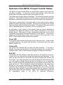
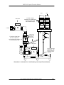
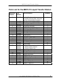
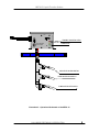
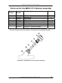
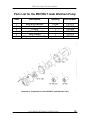
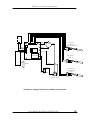
OPERATING INSTRUCTION MANUAL
MD70-15
Liquid Transfer Station
Hallmark Refining Corporation
1016 Dale Lane
PO Box 1446
Mount Vernon, WA 98274
Phone 360/428-5880
Toll Free 800/255-1895
Fax 360/424-8118
www.hallmarkrefining.com
Revised June 2008
MD70-15 Liquid Transfer Station
Statement of Warranty and Liability
All equipment manufactured by HRC is guaranteed against defects in materials
and workmanship for a period of six months from the date of shipment from our
factory. Any claimed defects must be reported, and the materials and/or
equipment must be returned freight prepaid, to our plant within the guarantee
period. Our liability for defects in material and/or workmanship shall be limited to
the replacing or repairing, at our option, such defective materials and/or
equipment at no cost to the purchaser. Any damages or loss occurring during
shipment are not covered by this warranty but are the responsibility of the
carrier(s). Please report all shipping damage to the carrier(s) immediately.
All materials and/or equipment furnished by other suppliers carry no warranty
except said supplier's warranty as to materials and workmanship. Transportation,
handling damage, wear and tear, and other causes of damage outside the
control of the manufacturer are not covered by this warranty. Under no
circumstances will HRC be responsible for any damage, loss or liability of any
nature arising out of the installation and/or use of the materials and or use of
equipment furnished.
There are no other warranties, expressed or implied, except as stated above.
The warranty becomes null and void if any devices or accessories other than
those distributed or officially recommended by HRC, are installed, or attached to
this equipment.
HALLMARK REFINING CORPORATION
1
MD70-15 Liquid Transfer Station
Table of Contents
Statement of Warranty and Liability..................................................................1
Overview of the MD70-15 Liquid Transfer Station ...........................................3
Installation of the MD70-15 Liquid Transfer Station ........................................4
Operation of the MD70-15 Liquid Transfer Station ..........................................5
Parts List for the MD70-15 Liquid Transfer Station..........................................7
Parts List for the MD70-15 Y-Strainer Assembly..............................................9
Parts List for the MD70RLT Iwaki Walchem Pump.........................................10
Instructions for Using Iron Out in Photo Lab Applications...........................11
Troubleshooting Guide for the ........................................................................12
MD70-15 Liquid Transfer Station .....................................................................12
Interpretation of the LED’s on the Control Box..............................................14
Maintenance Procedures for the MD70-15......................................................15
Liquid Transfer Station.....................................................................................15
Filter Maintenance ...........................................................................................15
Holding Tank Maintenance ..............................................................................15
Pump Head Maintenance ................................................................................15
Specifications for the MD70-15 Liquid Transfer Station................................17
Illustrations
Illustration 1:
Illustration 2:
Illustration 3:
Illustration 4:
Illustration 5:
Illustration 6:
Specifications for Installing the Liquid Transfer Station ..................4
Schematic for “Soft Plumbing” the Liquid Transfer Station .............6
Operational Schematic of the MD70-15..........................................8
Exploded View of the Y-Strainer Assembly ....................................9
Exploded View of the MD70RLT Iwaki Walchem Pump ...............10
Wiring Schematic for the MD70-15 Control Box ...........................16
HALLMARK REFINING CORPORATION
2
MD70-15 Liquid Transfer Station
Overview of the MD70-15 Liquid Transfer Station
HRC pump stations are designed to resist leakage and corrosion from all photo
processing chemicals. Magnetic Drive Pumps do not use seals, eliminating
leakage through the pump assembly. They are thermally protected and within
reasonable limits can be run dry without pump damage. They are CPVC
constructed with the motor totally enclosed and fan cooled.
The MD70-15 pump station is equipped with an in-line filter screen. The trouble
free operation of this pump station is critically dependent on the proper
maintenance of its in-line filter screen system (Y-Strainer). The pump station
must be installed so that the screen is easily accessible. This manual’s
page on pump station maintenance further elaborates on the details of cleaning
the Y-Strainer screen. The procedure is quite simple and absolutely essential.
In most instances, this pump station will arrive configured with a sealed lid. The
lid is attached to the tank with stainless steel bolts and nuts and functions as a
barrier against gases, which may be present in your drain system. The sealed
lid is not intended as a barrier against solution overflow. The pump is also
equipped with a high liquid level alarm system; should the incoming solution
reach the level of this alarm switch, an audible buzzer will sound. Do not
disable this switch. If an audible alarm is experienced regularly, the pump
station is not working properly. The filter may be blocked or the pump station
may be unable to keep up with the incoming flow of solution. Consult the
troubleshooting guide for further information.
This system has been designed to function as an under-the-sink transfer station.
It is therefore frequently “hard” plumbed making it very difficult to perform service
work at a later time. In order to service the in-line filter screen, as well as
perform any other needed repairs, it is recommended that this station be
installed with either quick disconnect fittings or short sections of
reinforced tubing.
A receptacle outlet should be installed near the equipment and should be easily
accessible. Avoid the use of long extension cords.
HALLMARK REFINING CORPORATION
3
MD70-15 Liquid Transfer Station
Installation of the MD70-15 Liquid Transfer Station
When installing the MD70-15 Liquid Transfer Station, several things should be
taken into consideration.
1. The MD70-15 Liquid Transfer Station must be “soft plumbed”. Quick
disconnects must be installed on all PVC inlet fittings so the unit can be
removed for routine maintenance procedures.
2. The discharge pipes on the unit must be the proper diameter for the unit to
function properly. Refer to Illustration 1 for further information. The chart
indicates the amount of head pressure the pump can accommodate at
various pipe diameters. Do not exceed these specifications!!
3. The unit must be installed near an electrical outlet, use of extension cords is
not recommended. As the unit is normally under a sink, a GFI outlet is
preferred.
4. The red handled ball valves and filter screen assembly must be accessible.
The Y-strainer on the MD70-15 Liquid Transfer Station should be cleaned
daily for the proper trouble free operation of this unit.
5. The discharge pipes from the unit should not contain more than two elbows;
one of which is included with the unit following the check valve. Additional
fittings significantly reduce the ability of the pump to perform its job properly.
Approximately two feet of head can be subtracted for each additional
fitting.
6. Hallmark Refining Corporation recommends that all pipe entering or exiting
the MD70-15 Liquid Transfer Station be Schedule 80 or higher.
Product
MD70RLT
MD70RLZT
MD100RLT
1” Exit Pipe
26 Feet
15 GPM
26 Feet
10 GPM
29 Feet
18 GPM
1 ½” Exit Pipe
22 Feet
15 GPM
25 Feet
10 GPM
22 Feet
23 GPM
2” Exit Pipe
21 Feet
15 GPM
24 Feet
10 GPM
21 Feet
24 GPM
Illustration 1: Specifications for Installing the Liquid Transfer Station
HALLMARK REFINING CORPORATION
4
MD70-15 Liquid Transfer Station
Operation of the MD70-15 Liquid Transfer Station
The MD70-15 Liquid Transfer Station is a pump station used to move liquid from
one place to another. In the most common case scenario, liquid enters the
holding tank of the liquid transfer station from a pipe at the sink.
The holding tank contains three float switches. The bottom float switch turns the
system off. The middle float switch turns the system on and the top float switch
activates an alarm that sounds when there is too much liquid in the holding tank.
When there is enough liquid in the holding tank to cover both the bottom and the
middle float switch, the pump is activated. The pump will continue to run until the
liquid level drops below the bottom float switch. The pump will then stop running
until it is activated again by the addition of fluid to the holding tank.
As mentioned in the overview of this manual, there are certain maintenance
procedures that must be followed for the optimal performance of the liquid
transfer station. More detail of these maintenance procedures can be found
immediately following the troubleshooting section in this manual. In an effort to
simplify the troubleshooting process, there are lights on the control box of the
MD70-15 that indicate certain conditions are present.
Green LED
A solid green LED indicates that the unit has AC electrical power. Under normal
operating conditions, the green LED will flicker continuously when the circuit
board is ready to run.
Yellow LED
The yellow LED indicates that the pump has been activated. If this light is
blinking, the pump was activated in an abnormal sequence and a system error
condition exists. Refer to the troubleshooting guide for additional information.
Red LED
The blinking red LED indicates a fault has occurred in the operation of the unit.
Usually, this is an indicator that the high level alarm has been activated. In this
case, an alarm will sound to inform the user that the holding tank contains too
much liquid. As a safety precaution, the top float switch will activate the pump to
run if the middle or bottom float switch did not activate to turn on the pump.
After 2 minutes of the pump operating while the unit contains too much liquid, the
pump will turn off. This is intended to reduce the likelihood of the pump motor
burning out from running continuously for extended periods of time. The high
level alarm can be silenced, but the station will continue to turn on the pump and
alarm every thirty minutes for two minute intervals until the situation is resolved
and the float switch has been released. Refer to the troubleshooting guide and
the interpretation guide of the LED’s for additional information.
HALLMARK REFINING CORPORATION
5
MD70-15 Liquid Transfer Station
Vent
Inlet
2" Rubber Couplers
Available at any hardware store
or plumbing supply house.
Use all stainless clamps.
1" Ball Valve
3
1" Outlet
19
1
Venting tube
prevent s the
pump from
vaporlocking
1" True Union Check Valve
This valve is directional.
Arrow indicating flow direction
is on the side of the valve.
14
25
1" Ball Valve
28
32
19
23
Pick up intake hose
for the pump. This
MUST be directed
toward the bottom
of the tank.
Illustration 2: Schematic for “Soft Plumbing” the Liquid Transfer Station
HALLMARK REFINING CORPORATION
6
MD70-15 Liquid Transfer Station
Parts List for the MD70-15 Liquid Transfer Station
Reference
Number
Part
Number
Part Description
1
905-170
Holding Tank Assembly
Complete with base plate, rubber feet,
pick up tube assembly and gasket
Tank Cover Small (8 ¼” x 5 ½”)
Tank Cover Large (8 ¼” x 8 ½”)
Holding Tank Gasket
Control Box Assembly
MD70-15 Drop in Assembly
Male Adapter for Sink and Vent
5 Amp Circuit Breaker
Power Cord
Circuit Board
Check Valve 1"
Alarm Buzzer
PVC Elbow FPT x FPT
Ball Valve 1"
Male Adapter 1"
Hose Fitting 1"
Hose Clamp
Complete Y-Strainer Assembly
Y-Strainer Screen (Orange)
Y-Strainer Retainer Clip
3
14
19
23
25
28
32
914-500
914-502
200-014
915-120
915-049
436-020
741-005
728-018
740-006
502-010
730-003
808-010
505-010
836-010
336-010
522-012
540-008
540-012
540-014
519-010
918-003
915-017
524-001
702-285
702-046
884-005
210-002
211-002
807-010
Tank Adapter 1”
Pick Up Tube Assembly
Float Switch Assembly
Liquid Level Switch
MD70RLT Pump
MD70 Impeller Assembly
PVC Nipple 1"
SS Hex Nut
SS Hex HD Cap Screw
Elbow 1” Slip x FPT
HALLMARK REFINING CORPORATION
Quantity
1
1
1
1
1
1
2
1
1
1
1
1
1
2
1
2
2
1
1
1
1
3
1
1
4
10
10
2
7
MD70-15 Liquid Transfer Station
ALARM
TO 115 AC POWER
TO PUMP MOTOR
TROUBLE SHOOTING LEDS
5
CIRCUIT BREAKER
PUSH TO RESET
POWER LED
HIGH LEVEL ALARM SWITCH
PUMP MOTOR ON SWITCH
PUMP MOTOR OFF SWITCH
Illustration 3: Operational Schematic of the MD70-15
HALLMARK REFINING CORPORATION
8
MD70-15 Liquid Transfer Station
Parts List for the MD70-15 Y-Strainer Assembly
Reference
Number
Part
Number
Part Description
Quantity
1
2
3
4
5
6
7
NA*
540-014
540-012
NA*
540-013
NA*
NA*
540-008
Y-Strainer Housing
Retainer Clip
Filter Screen
Filter Body
O Ring
Cap
Support Ring
Complete Y-Strainer Assembly
1
1
1
1
1
1
1
(Includes 2 preassembled elbows and tubing)
* The entire assembly must be purchased. These parts are not available separately.
7
6
5
4
3
2
1
Illustration 4: Exploded View of the Y-Strainer Assembly
HALLMARK REFINING CORPORATION
9
MD70-15 Liquid Transfer Station
Parts List for the MD70RLT Iwaki Walchem Pump
Item
Description
Quantity
Part Number
1
2
3
4
5
6
Bolts and Washers
Front Casing
O-Ring
Impeller with Spindle
Rear Casing
Magnetic Drive Assembly
6 Sets
1
1
1
1
1
210-075
702-094
702-069
702-073
702-074
702-075
Illustration 5: Exploded View of the MD70RLT Iwaki Walchem Pump
HALLMARK REFINING CORPORATION
10
MD70-15 Liquid Transfer Station
Instructions for Using Iron Out in Photo Lab
Applications
Iron Out should be used as a preventative measure to reduce iron build up in
photo labs that use steel wool type silver recovery units. Photo labs that operate
a liquid transfer station are at the most risk of damage from iron build up.
Excessive iron buildup will cause liquid transfer station malfunction and clogged
pipes. It is recommended that Iron Out be used weekly for best results.
Items needed:
Warm water
1 cup of Iron Out
2.5 Gallon Container
1. Slowly mix 1 cup of Iron Out with 1 gallon warm water in a container. Be
sure the Iron Out dissolves completely.
2. Pour the dissolved solution down the drain, preferably after the lab has
closed. This allows the Iron Out sufficient time to sit in the liquid transfer
station’s holding tank or pipes and dissolve iron buildup.
DO NOT pour the powdered Iron Out down the drain first, then flush the
sink with water. Undissolved Iron Out tends to crystallize and contributes
to the buildup problem.
Iron Out will not solve current drainage problems. It is intended as a preventative
measure only. Current problems need to be addressed and resolved before Iron
Out can be effective.
HALLMARK REFINING CORPORATION
11
MD70-15 Liquid Transfer Station
Troubleshooting Guide for the
MD70-15 Liquid Transfer Station
PROBLEM
POSSIBLE SOLUTION
The pump is running, but is Y-Strainer screen could be plugged. See Filter Maintenance.
moving little or no solution. The
red LED is blinking and the Pick up tube inside the tank could be clogged.
alarm is sounding.
Ball valves (see diagram) may have been left closed after last
maintenance procedure. See Holding Tank Maintenance.
The impeller assembly may be worn or damaged. See Pump
Head Maintenance.
The pump may have lost it's prime. With the system on, twist
the Y-Strainer screen cap off until a drip of liquid comes out.
This should remove any air locks. Tighten the cap immediately.
How many elbows are on the discharge side of the MD70-15
motor? No more than two are recommended. Refer to the
installation guide in this manual for further information.
The discharge pipe should be no smaller than 1” and no larger
than 2”. If the pipe is smaller than 1”, a plumber cannot snake
the line. If the pipe is larger than 2”, too much head pressure is
created on the system. Refer to the installation chart in this
manual for further information.
The float switches need to be The system is probably "hard plumbed". It is recommended that
checked, but the holding tank is a plumber install flexible plumbing or a quick disconnect. As a
temporary solution, try jiggling the holding tank to dislodge
not accessible.
debris.
The
9-volt
battery
needs The system is probably "hard plumbed". It is recommended that
replacing, but the control box a plumber install flexible plumbing or a quick disconnect.
lid cannot be removed.
The pump station does not have Has the breaker at the main power panel been thrown? Check
and reset if necessary.
a green power light.
Has the breaker at the pump station been thrown? Reset the
circuit breaker on the control box and check for the reason it
blew. The four most common reasons are the red handled ball
valves are closed, the check valve is not operating/installed
properly, the impeller is damaged or the pipes after the liquid
transfer station are blocked.
Is there a switch in the lab that controls power to the electrical
outlet?
Has the GFI circuit breaker at the outlet been checked?
HALLMARK REFINING CORPORATION
12
MD70-15 Liquid Transfer Station
PROBLEM
POSSIBLE SOLUTION
The pump station is overfilling, The pump may have lost it’s prime. With the system on, twist
or appears to be leaking. The the Y-Strainer filter cap off until a drip of liquid comes out. This
red LED is blinking and the alarm should remove any air locks. Tighten the cap immediately.
Airlocks occur because of the introduction of too much liquid at
is sounding.
one time. If this is a continuous problem, the drain hole of the
sink may need to be shrunk. Hire a plumber to restrict the size
of the drain hole in the sink so that too much liquid cannot be
introduced into the pump station at one time.
Y-Strainer filter could be plugged. See Filter Maintenance.
The pick up tube inside the tank could be plugged. There is
an 8” piece of 1” diameter tubing on the elbow inside the
holding tank. This tubing is cut on the bias so it can lie on the
floor of the tank and prevent debris from being sucked into the
pump inlet line. If this tubing is removed for cleaning, it MUST
be replaced and angled toward the bottom of the tank.
Is Iron Out being used on a regular basis? It is recommended
that one cup of Iron Out be pre-mixed with one gallon of water
and poured down the sink.
This should be done weekly.
Refer to the Instructions for Using Iron Out in Photo Lab
Applications in this user manual for further instructions.
The float switches may be dirty, blocked or detached. See
Holding Tank Maintenance.
The red handled ball valves may have been left closed after
last maintenance procedure. Make sure they are open.
Power to the pump station may be connected to a switch and
the switch is turned off.
Breaker at control box or main circuit breaker may be thrown.
Reset breaker and investigate the cause.
The discharge pipe should be no smaller than 1 ½” and no
larger than 2”. If the pipe is smaller than 1 ½”, a plumber
cannot snake the line. If the pipe is larger than 2”, too much
head pressure is created on the system.
The pump is making a loud noise The impeller assembly on the pump may be worn and in need
of replacement. See Pump Head Maintenance.
and/or is pumping
very slowly.
HALLMARK REFINING CORPORATION
13
MD70-15 Liquid Transfer Station
Interpretation of the LED’s on the Control Box
As stated in the Operations section of this manual, the MD70-15 Liquid Transfer
Station has a series of LED’s on the face of the control box that indicate certain
conditions are present during operation of the system.
The following table explains these LED indicators in greater detail.
Green
LED
Appearance
Solid Light
Condition Present
Electrical current is present at the system. The unit
has power.
•
Blinking Light
Yellow
LED
Solid Light
The unit is operating normally. The circuit board in the
system is performing as programmed.
The pump has been activated to run.
•
Blinking Light
If the pump is not running, the pump motor may be
burnt out.
The top float switch has been activated and a time
out sequence has occurred.
•
Red LED
If the system is completely full of liquid and the light is
still solid green and no other lights are present, the
circuit board is inoperable.
If the top float switch is activated for more than five
minutes, the pump will shut off to avoid burning out the
pump motor. An alarm will sound. The red LED will
be blinking. The alarm can be cancelled. The system
will turn on and repeat this cycle every thirty minutes
for five minutes at a time until the problem is cleared.
Refer to the troubleshooting guide for possible
solutions.
Blinking Light
no Alarm
A fault has occurred in the operation of the unit.
Blinking Light
with Alarm
A fault has occurred in the operation of the unit. The
top float switch has been activated.
•
•
The middle float switch has activated the pump to run
without the bottom float switch being activated. Refer
to Holding Tank Maintenance.
There are many reasons that the top float switch could
be activated. Refer to the troubleshooting guide for
possibilities. The most common problem is that the YStrainer filter needs to be cleaned. Under normal
operating conditions, the unit should turn on and off
without activating the high level alarm.
HALLMARK REFINING CORPORATION
14
MD70-15 Liquid Transfer Station
Maintenance Procedures for the MD70-15
Liquid Transfer Station
Filter Maintenance
The Y-Strainer screen should be cleaned daily. Heavy algae or other particulate build-up will necessitate
more frequent cleaning. Failure to service this screen will result in a reduced pumping rate and could
damage the pump head assembly. Service this assembly using the following procedure:
1) Disconnect the pump station from the power supply.
2) Close the 1” valve from the holding tank to the Y-Strainer (see diagram) and the 1” valve to the drain.
3) Unscrew the filter assembly from its housing.
4) Remove the retaining cap at the bottom of the filter assembly (it snaps off) and slide the screen out of
the filter assembly. The screen can then be cleaned by rinsing it in a stream of tap water and manually
removing any sediment build-up. DO NOT CLEAN THE SCREEN IN THE SINK WITH THE MD70-15!!
5) Replace the screen in the assembly and snap the retaining cap in place. This retaining cap MUST be
present or the screen is useless.
6) Screw the filter assembly into the Y-Strainer housing.
7) Reconnect the pump station to the power supply.
8) Open the valves that were closed prior to the maintenance procedure and inspect for leaks.
Holding Tank Maintenance
Under certain conditions and particularly after extended use, it will be necessary to clean the holding tank.
Service this using the following procedure:
1) Disconnect the pump station from the power supply.
2) Close the 1” valve from the holding tank to the Y-Strainer (see diagram) and the 1” valve to the drain.
3) Disconnect the pump station from inlet and vent plumbing. This will require the help of a plumber if
these connections have been “hard plumbed”. The plumber should install flexible tubing or a quick
disconnect.
4) Remove wing nuts holding the lid to the holding tank and lift the entire lid assembly from the tank. The
assembly will still be attached to the pump station via the power cord to the pump. Use care not to
damage the exposed float switches.
5) Check the operation of the float switches. Clean the switches and the inside of the holding tank. An old
toothbrush works well.
6) Rinse the holding tank of any accumulated sludge-like material. Use a Wet/Dry Vacuum if necessary to
remove sludge.
7) Reattach the lid assembly to the holding tank with the wing nuts.
8) Reconnect the pump station to the power supply.
9) Open the valves that were closed prior to the maintenance procedure and check for leaks.
NOTE: When reassembling the lid, be certain that the float switches are not obstructed by the pick up tube
assembly at the bottom of the holding tank. The float switches must operate freely!
Pump Head Maintenance
On certain occasions, it may be necessary to change the liquid end of the MD70-15RLT pump. Follow this
procedure to minimize the difficulty in accessing the liquid end of the pump. If components are being
replaced, it is highly advisable to replace the complete liquid end (LMD70RT) to prolong the life of the other
components.
1) Disconnect the pump station from the power supply.
2) Close the 1” valve from the holding tank to the Y-Strainer (see diagram) and the 1” valve to the drain.
3) Unscrew and remove check valve from the pump.
4) Remove screws holding the front casing of the pump.
5) Carefully pull the front case away from the pump motor. There is a certain amount of flex in the tubing to
the holding tank, which will allow the pump head to be pulled away from the pump motor.
6) The impeller, rear case, and O-Ring can now be removed and the front case unscrewed from its
connection point.
7) Replace worn parts and reassemble, making certain to wrap the threaded fitting which attaches to the
front case with teflon tape.
HALLMARK REFINING CORPORATION
15
MD70-15 Liquid Transfer Station
9V BATTERY
-
+
C T C M B
J1 1 2 3 4 5 6 C
SW 1
BLACK RED +
RED +
4
3
2
S
WI
W4
TC
HE
D
LO
AD
RE
TU W 2
RN
CP
U
BLACK
PUMP
GREEN
TOP SW ITCH
ALARM LEVEL
PUMP ON ALARM SOUND
W HITE
RELAY
AC
LO W 3
W
1
BLACK - J2
TRANSFORMER
AC
IN W 1
MIDDLE SW ITCH
PUMP ON
SPEAKER
B
L
A
C
W HITE
BLACK
BOTTOM SW ITCH
5
LOW LIQUID LEVEL
PUMP OFF
CIRCUIT BREAKER
5 AMP
AC POW ER IN
120 VAC 50/60 Hz
Illustration 6: Wiring Schematic for the MD70-15 Control Box
HALLMARK REFINING CORPORATION
16
MD70-15 Liquid Transfer Station
Specifications for the MD70-15 Liquid Transfer
Station
Pump Station Size
Holding Tank Capacity
Shipping Weight
Maximum Output
Maximum Head
Sample Output on Performance Curve
Power Requirements
Connections
Motor UL File Number
Pump Station UL File Number
20”L x 14”W x 20“H
3½ Gallons
39 lbs.
25.6 Gallons
31.8 ft.
12 GPM @ 25 ft.
115 VAC 60Hz
1” NPTM
E89768
E159207
HALLMARK REFINING CORPORATION
17