1
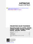
USER’S MANUAL
MODEL: CRF940
The FCC Wants You to Know
This device complies with Part 15 of FCC Rules. Operation is subject to the following two conditions :
(1) This device may not cause harmful interference, and (2) this device must accept any interference received,
including interference that may cause undesired operation.
Your modulator might cause TV or radio interference even when is operating properly. To determine whether
your modulator is causing the interference, turn it off. If the interference goes away, your modulator is causing
it.
Try to eliminate the interference by :
• moving your RF Modulator away from the receiver
• connecting your RF Modulator to an outlet that is on a different electrical circuit from the receiver
• contacting your local store for help
If you cannot eliminate the interference, the FCC requires that you stop using your RF Modulator. Changes or
modifications not expressly approved by the party responsible for compliance could void the user's FCC
authorization to operate this equipment.
You can use your CRF940 Audio/Video Selector to connect up to four audio/video components (such as
direct-to-home satellite systems, VCRs, DVD players, laserdisc players, cable boxes, or video game system)
to a single TV. You can connect S-video cables directly to the selector for optimum picture quality.
Depending upon your audio/video system setup, you might also need additional cables of adapters to connect
all of the desired components.
Use RCA cables to connect audio and video devices, and S-video cables to connect video devices to the
selector.
AUDIO
AUDIO
VIDEO
L
RF
TO TV
RF
OUTPUT
AUDIO
VIDEO
L
R
OUTPUT
RCA
CONNECTOR
AUDIO
VIDEO
L
S
ANT IN
CH.
3 4
Note :
VIDEO
S
R
INPUT 1
S
9VDC
100mA
+
R
INPUT 2
INPUT 3
S-VIDEO
CONNECTOR
To receive video output from the OUT S-video Jack on the back of the selector, you must use an
S-video cable to connect a video source to one of the IN S-video jacks
PLACING THE SELECTOR
You can set the selector on just about any flat surface. For the best results, do not place it on top of a TV or
other electrical appliance.
Important : If you place the selector on top of your TV, electromagnetic interference from the TV might distort
the sound from any devices connected to the selector. If this happens, move the selector away from the TV.
CRF940_01
CONNECTING DEVICES TO THE SELECTOR
TV OR RECEIVER
TV WITH
SINGLE “F”
F JACK
AND S-VIDEO
AUDIO
RF
TO TV
VIDEO
AUDIO
VIDEO
L
AUDIO
VIDEO
AUDIO
L
S
ANT IN
VIDEO
L
S
S
9VDC
100mA
+
R
CH.
3 4
OUTPUT
R
INPUT 1
R
INPUT 2
INPUT 3
ANTENNA OR
CABLE BOX
CAMCORDER
OR SATELLITE
RECEIVER
1
2
3
4
Iinput
ON
1. Connect the audio outputs for each device to a set of IN AUDIO jack (1-3) on the back or 4 on the front of
the selector.
2. If a device you want to connect does not have an S-video cable, connect its video output to IN VIDEO for
that device on the back of the selector, Or, if the device has an S-video cable, connect it to the S-video IN
jack for that device on the back of the selector.
Note: Do not connect the component’s video output to both INPUT-V (1-4) and S-VHS INPUT (1-4).
3. If the TV or monitor you want to connect does not have an S-video cable, connect its video input to OUT
VIDEO on the back of the selector.
Note: Do not connect the TV or monitor’s video input to both OUT-PUT V and OUT-PUT S-VHS.
4. Auto detector
When the CRF940 doesn’t detect the signal from the 4 inputs, it will automatically process the signal from
the “F” connector of “ANT IN” to RF output
5. Synchronize Recording function:
If you choose any of the 4 inputs to process the program, you may also record the program at the same
time from the Audio/Video/S-video output.
USING THE SELECTOR
Turn on the device you want to use. Press the button that corresponds to the device on the front of the
Audio/Video Selector. The indicator turns on showing the power supply is connected correctly and a video
source is being passed through the switch. If you do not see video output for the device you selected check to
make sure you pressed the correct button and your input/output cables are properly connected.
NOTE: THE RED LED ONLY LIGHTS TO SHOW VIDEO IS PRESENT. IT IS NOT A POWER INDICATOR
FOR THE SWITCH.
CRF940_01