1
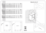
INSTALLATION AND USER INSTRUCTIONS
FOR
AS3 & AS4 VERTICAL TRAVEL SALAMANDER
GRILLS
IS384
ECN3345
Page 1
Please read the following carefully before using this appliance.
Warnings and Precautions
Please ensure that all commissioning checks and initial start-up procedures have taken
place.
This manual should be kept in a safe and accessible place for future reference.
This appliance is designed for professional use and must only be operated by qualified
personnel.
It is mandatory that all appliances with a power rating over 3kW are installed,
commissioned and serviced by a qualified and competent person as defined by the
regulations in force in the country of installation.
Failure to comply will invalidate the warranty.
Please ensure that the appliance is serviced regularly by a competent catering
equipment engineer.
WARNING
!
!
Disconnect the unit from the electricity supply before servicing or undertaking any
electrical maintenance.
Parts of this unit may become hot in normal use, therefore suitable precautions must
be taken to avoid accidental contact.
IS384
ECN3345
Page 2
SECTION 1 – Introduction
Technical Data
Model number
Overall height (mm)
Width (mm) (inc handles)
Depth (mm) (inc handles)
Weight (Kg)
Electricity supply requirements
Electricity supply connection
Power rating @240V (kW)
AS3
500
600
550
45
Single phase 12.2 Amps
Single phase 13A plug
2.8
AS4
500
600
550
47.5
Single phase 18.8 Amps
5 Way terminal block
4.5
( Fig 1)
Check list of enclosures
Please ensure that the following items are included with this piece of equipment:
Model
Drip/Crumb Tray
Wire Tray
Wire Support Rack
Heat Shield
User Instructions
Guarantee card
IS384
ECN3345
AS3/AS4
1
1
1
1
1
1
Page 3
Tick ( )
SECTION 2 - INSTALLATION
2.1 PREPARATION
1. Remove all packaging materials and protective coatings from both the outer body and
the drip/crumb tray prior to installation.
2. Remove transportation screws from rear panel of unit (see fig 2).
3. Do not use handle to carry unit.
2.2 SITING
1. The appliance must be installed on a non-combustible, level surface in a suitable position
that is well lit, and positioned so as to prevent accidental touching.
2. Partitions, walls, kitchen furniture and other materials less than 100 mm from the
appliance should be made from non-combustible material.
3. Ensure there is a free flow of air and adequate ventilation around the appliance, and that
no vents are blocked.
4. Silverlink Vertical Travel Salamanders can be either installed on a counter or wall
mounted using wall mounting brackets (see section 9 - optional accessories).
INSTALLING A WALL MOUNTED UNIT
1.
2.
3.
4.
5.
6.
Refer to dimensional drawing (fig 1) and drawing of mounting holes (see fig 2).
Use wall mounting kit supplied by Lincat (optional extra).
Loosen 4 screws in back of unit.
Fit brackets (x 2) to back of unit using existing screws.
Drill 4 holes in wall according to drawing below.
Secure unit to wall.
LOOSEN SCREWS (4 OFF)
IN BACK OF UNIT
FIT BRACKETS (2 OFF)
ONTO 4 SCREWS
Mounting hole centres to
be used when unit is wall mounted.
TRANSPORTATION
SCREWS (2 OFF)
TO BE REMOVED
(Fig 2)
IS384
ECN3345
Page 4
2.3 ELECTRICAL SUPPLY AND CONNECTION
Ensure that isolation sockets are free from obstruction and are easily accessible.
Model AS3 is fitted with a 3-pin plug for connection to a standard switched socket.
Model AS4 must be connected to the electricity supply by a qualified electrician. Ensure that
the supply is adequate for the unit to be installed.
The appliance should be connected to the mains via a suitable isolating switch, having at least
3mm contact separation in all poles.
2.4 CONTROL PANEL
TIMER
KNOB
ON/OFF
NEON SWITCH
2.5 PREPARATION FOR USE
1. Ensure element hood moves freely and remains at set height when released.
2.6 USER INSTRUCTION
Ensure that the person responsible understands how to safely operate, clean and switch off
this unit and is made aware of the position of the isolating switch.
Note: This manual must be kept in a safe and accessible place for future reference.
SECTION 3 – OPERATION
1.
2.
3.
4.
5.
6.
7.
8.
Raise element hood to highest position.
Switch on Salamander – on/off switch will illuminate.
Warm up time is 10 - 15 minutes.
Place plates or dishes on grill tray.
Adjust height of hood to desired position for food.
Raise hood to maximum height before removing any plates or dishes.
Ensure sliding grill tray is always fully pushed back after use.
The audible timer does not control the power. Unit must be switched off at on/off switch.
IS384
ECN3345
Page 5
Warning
• This appliance should not be operated with hood in lowest position for longer than
30 minutes.
• Make sure that food does not come into contact with heating elements, to prevent
soiling or damage.
SECTION 4 - CLEANING
Warning
Disconnect the unit from the power supply before carrying out any cleaning operations.
KNURLED KNOBS
HEAT SHEILD
W IRE TRAY
SUPPORT
W IRE TRAY
RUNNER
DRIP/CRUMB
TRAY
W IRE TRAY
GRID
(Fig 3)
1. Lift out wire tray grid and drip/crumb tray.
2. Slide out wire tray support.
3. Loosen knurled knobs and lift off heat shield over knobs.
After use, clean the unit using a warm detergent solution.
Do not use abrasives.
Do not use any products containing chlorine to clean stainless steel surfaces.
Do not clean the appliance using a water jet.
In extreme conditions a branded cleaner such as “Carbon off” may be used.
IS384
ECN3345
Page 6
REASSEMBLY AFTER CLEANING
1. Slide wire tray support back over wire tray runners.
2. Place drip/crumb tray into wire tray support, taking care that the stops on the drip/crumb
tray are positioned beyond the front uprights of the wire tray runners.
SECTION 5 – SERVICE AND MAINTAINANCE
Catering equipment should be routinely serviced to ensure a long and trouble free life. With
this in mind it is recommended that appliances are serviced every six months by a competent
engineer.
For help regarding the installation, maintenance and use of your Lincat equipment, please
call:
LINCAT GROUP SERVICE HELP DESK
01522 875520
Please quote both the model and serial numbers from the data plate attached to the unit and
give brief details of the service requirement.
Lincat reserve the right to carry out any work under warranty during normal working hours,
i.e. Monday to Friday, 8.30 a.m. - 5.30 p.m.
AUTHORISED SERVICE AGENTS
We recommend that all servicing, other than routine cleaning, be carried out by our
authorised service agents and will accept no responsibility for work carried out by other
persons.
SECTION 6 - SPARES LIST
AS3
Part number
EL50
KN95
KN163
PL201
RO35
SW69
SS05
WI16
WI17
WI18
DR62
IS384
ECN3345
AS4
Part numbers
EL237
KN95
KN163
TE45
CO214
RO35
SW69
SS05
WI16
WI17
WI18
DR62
Part description
Heating Element
Timer Control Knob
Knurled Knob
Cable & Plug
Terminal Block Connector
Contactor
Nylon Roller
On/Off Switch
Counterbalance Strap
Wire Tray Runner
Wire Tray Support
Wire Tray Grid
Drip/Crumb Tray
Page 7
SECTION 7 - GENERAL FAULT FINDING
Element will not heat up
Is the unit
connected to the
mains and the unit
switched on?
No
Plug or connect the
unit and switch on.
No
Reset isolator or
replace fuse.
Yes
Check mains
isolator or fuse.
Yes
Consult service
engineer.
SECTION 8 - GUARANTEE
All Silverlink equipment is fully guaranteed for parts and labour for a period of twelve
month.
The guarantee does not cover:
1. Accidental breakage or damage
2. Operational misuse, wear and tear from normal usage, incorrect adjustment, or neglect.
3. Incorrect installation, maintenance, modification or unauthorised service work.
SECTION 9 - ACCESSORIES
The following accessories are available for your Lincat salamander grill.
Accessory
Wall Mounting Brackets AS3
Wall Mounting Brackets AS4
IS384
ECN3345
Part
number
BR41
BR51
Page 8