1
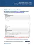
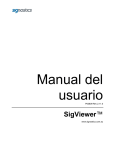
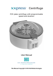
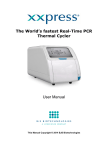
CRYOGAUGE 200 CAPACITANCE LEVEL GAUGE INSTALLATION & OPERATING INSTRUCTION MANUAL Revision 1-0 Date 20-08-15 Notes FIRMWARE REV 2.31 Quantum Cryogenics Units 1-3 Hatherleigh Industrial Estate Hatherleigh Devon, EX20 3LP T. +44 (0) 1844 339993 Quantum Cryogenics 7A Lupton Road Thame Oxfordshire, OX9 3SE F. +44 (0) 1844 339996 W. www.quantumcryogenics.com www.quantumcryogenics.com COPYRIGHT QUANTUM CRYOGENICS. 2015 © THIS DOCUMENT IS THE PROPERTY OF QUANTUM CRYOGENICS. NO PART OF THIS DOCUMENT MAY BE REPRODUCED TO A THIRD PARTY IN ANY FORM WITHOUT THE WRITTEN PERMISSION OF QUANTUM CRYOGENICS. QUANTUM CRYOGENICS IS A TRADING NAME OF QUANTUM PRODUCTION LTD. www.quantumcryogenics.com TABLE OF CONTENTS 1 SAFETY WARNINGS ........................................................................................................ 2 2 INTRODUCTION / PRODUCT DESCRIPTION...................................................................... 4 2.1 3 VISUAL REFERENCE GUIDE ...................................................................................... 6 INSTALLATION................................................................................................................ 8 4 3.1.1 PRE-FITTING CHECKS ........................................................................................ 8 3.1.2 FITTING ............................................................................................................ 8 3.1.3 LEVEL DISPLAY OFFSET .................................................................................. 12 3.1.4 OPERATING AT HIGH PRESSURES ................................................................... 12 OPERATION .................................................................................................................. 14 4.1 CONTROLS AND INDICATORS ............................................................................... 14 4.2 LCD DISPLAY INDICATIONS ................................................................................... 14 5 MAINTENANCE ............................................................................................................ 17 5.1 SERVICING ............................................................................................................ 17 5.2 CALIBRATION ........................................................................................................ 18 5.3 0% LEVEL SET ....................................................................................................... 18 5.4 100% LEVEL SET ................................................................................................... 20 5.5 RESTORE DEFAULT FACTORY VALUES ................................................................... 21 6 APPENDIX A - TECHNICAL SPECIFICATIONS.................................................................. 22 7 APPENDIX B – SETUP / ERROR CODES .......................................................................... 23 8 APPENDIX C - TROUBLE SHOOTING GUIDE .................................................................. 24 9 APPENDIX D – SPARES & ACCESSORIES ....................................................................... 26 10 APPENDIX E – CONFIGURATION CODES ................................................................... 27 11 APPENDIX F - SETTINGS / FITTING SUMMARY........................................................... 29 12 APPENDIX G - WARRANTY STATEMENT .................................................................... 30 13 APPENDIX H ............................................................................................................. 31 13.1 14 EC DECLARATION OF CONFORMITY (DoC)......................................................... 31 APPENDIX I - END OF LIFE DISPOSAL ........................................................................ 32 CRYOGAUGE 200 Page 1 of 32. www.quantumcryogenics.com 1 SAFETY WARNINGS THESE INSTALLATION AND OPERATION INSTRUCTIONS SHOULD BE READ COMPLETELY BEFORE INSTALLING OR OPERATING THE UNIT. THIS MANUAL ASSUMES THAT YOU ARE ALREADY TRAINED AND COMPETENT IN THE SAFE USE AND HANDLING OF CRYOGENIC FLUIDS AND CRYOGENIC / ELECTRICAL EQUIPMENT. Persons handling cryogenic liquids (liquid nitrogen, argon or carbon dioxide) should be aware of the dangers associated with their extreme cold and also the possibility of asphyxiation should large volumes of liquid or gas be discharged in confined or poorly ventilated areas. Persons handling liquid oxygen must also be aware of its potentially hazardous oxidising properties. Carbon dioxide additionally has toxic properties. Safety information provided by the suppliers of the cryogenic liquid must be read and understood before and followed during the installation and operation of this equipment. Failure to observe all safety precautions may result in property damage, personal injury, and / or death. DO NOT TOUCH COLD SURFACES OR LIQUID WITH BARE SKIN. CRYOGAUGE 200 Page 2 of 32. www.quantumcryogenics.com Cryogenic liquids are extremely cold and exposure of skin or eyes to liquid, cold gas or cooled objects may result in severe cold burn injury. The use of eye / face protection, insulated gloves, appropriate clothing and footwear is required. Take time to consider these and other safety precautions that must be observed. The standard CryoGauge must NOT be used with liquid oxygen. Only CryoGauge units which have been specially cleaned and specifically labelled as `CLEANED FOR OXYGEN SERVICE’ may be used with liquid oxygen. This is due to the increased risk of fire or spontaneous combustion in pure or enriched oxygen environments. The CryoGauge must be used only for the purpose and in the manner described in these instructions. If used for other purposes or in a manner not specified performance of this equipment may be impaired. The CryoGauge must not be used as a critical component in life support devices or systems. ELECTRICAL SHOCK CAN KILL Isolate all power supplies before opening enclosures or attempting to connect / disconnect equipment. All electrical installation must only be carried out by a qualified electrician or other suitably qualified and competent person. CRYOGAUGE 200 Page 3 of 32. www.quantumcryogenics.com 2 INTRODUCTION / PRODUCT DESCRIPTION The CryoGauge 200 is an indicating capacitance liquid level gauge for use with cryogenic fluids. Typically liquid nitrogen (LN2), liquid argon (Ar) and liquid carbon dioxide (CO2). This unit can only be used in liquid oxygen (O2/LOX) if specifically cleaned and labelled “CLEANED FOR OXYGEN SERVICE”. The CryoGauge assembly typically comprises of the following parts: 8mm OD rigid stainless steel probe. Display head enclosure with LCD display Threaded vessel adaptor fitting assembly NOTE: Probe length and vessel adaptor styles vary depending upon the model of vessel to which the CryoGauge is being fitted. It is important the correct probe dimensions are specified at time of ordering. Figure 2-1. CRYOGAUGE 200 WITH FITTING TOOLS CRYOGAUGE 200 Page 4 of 32. www.quantumcryogenics.com Figure 2-2. A4-00213 CRYOGAUGE 200 CRYOGAUGE 200 Page 5 of 32. www.quantumcryogenics.com 2.1 VISUAL REFERENCE GUIDE CALIBRATION / SETUP BUTTONS PCB PROBE CONNECTION TO DISPLAY HEAD (ON REVERSE SIDE) 0-100% LEVEL DISPLAY / LCD SCREEN LID AND FACEPLATE SCREWS Ø8MM PROBE VALID INDICATOR / HEALTHY HEARTBEAT PRESSURE RELIEF SEAL TUBING NUT SHOULDER OLIVE BREATHER HOLE (COVERED WITH PROTECTIVE TAPE) VESSEL ADAPTOR FITTING Figure 2-3. CRYOGAUGE 200 VISUAL REFERENCE GUIDE CRYOGAUGE 200 Page 6 of 32. www.quantumcryogenics.com Figure 2-4. CRYOGAUGE 200 EXAMPLE SERIAL NUMBER AND SPECIFICATION LABEL NOTE: The probe base capacitance value is written on the large brass nut inside the display enclosure. This capacitance value is for the probe alone and does not include the additional capacitance that can be provided by the CryoGauge PCB assembly and other wiring. This value is measured dry, at ambient temperatures and pressures. When viewing the capacitance output ‘C60’, the displayed value may vary from the written capacitance value under the same conditions. Figure 2-5. CRYOGAUGE BASE PROBE CAPACITANCE CRYOGAUGE 200 Page 7 of 32. www.quantumcryogenics.com 3 INSTALLATION 3.1.1 PRE-FITTING CHECKS IMPORTANT NOTE: Please read and understand these instructions below BEFORE attempting to fit CryoGauge. A vessel prepared for the fitting of a CryoGauge should be empty and depressurised. The vessel should have a threaded hole in its head suitable for accepting a threaded vessel adapter assembly (½” BSP Taper male default thread size unless specified). Various adapters to suit most configurations can be purchased from Quantum Cryogenics. CryoGauge probes are built to suit specific vessels and customer specified applications. It is important that the probe is of the correct length. It is recommended to carefully check the probe length and trial fit the probe before final fitting and tightening of tubing nut. Refer to drawing A4-00146 CRYOGAUGE PROBE POSITIONING DIAGRAM. The probe needs to be the correct length to allow measurement over the entire depth of the vessel. The CryoGauge cannot measure liquid levels below the bottom of the probe. The probe must not touch the bottom of the vessel, as this could result in a short circuit. The probe should contact the bottom of the vessel and then be raised 12mm (1/2”). The probe breather hole must be within the inner vessel, below the vessel adaptor, to allow liquid to rise and fall freely within the probe. The CryoGauge cannot measure liquid levels above the breather hole. The CryoGauge head enclosure should be a minimum of 100mm (4”) above the vessel adaptor. This is particularly important for high pressure and oxygen based applications. If upon trial fitting the CryoGauge does not meet the above conditions the probe is the wrong length and should be returned to Quantum Cryogenics. Under no circumstances should the CryoGauge be modified or shortened. IMPORTANT NOTE: A small black rubber grommet is mounted to the underside of all CryoGauge head enclosures. This is the pressure relief seal to prevent the head enclosure becoming pressurised in the event of a failure of the probe’s internal seals. Care should be taken to avoid obstructing or damaging this grommet. 3.1.2 FITTING Ensure that all threaded connections are clean and free of any debris. Ensure all tape and adhesive are removed from the breather hole and the end cap is removed from the open end of the probe. The appropriate parallel threaded adapter should be screwed into the vessel head onto the copper gasket, PTFE washer or O-ring seal and then tightened firmly with a spanner. If using a tapered threaded adaptor ensure an appropriate thread sealant such as PTFE tape is applied. Do not over-tighten connections as this will cause thread stress. CRYOGAUGE 200 Page 8 of 32. www.quantumcryogenics.com Figure 3-1. TAPE COVERING BREATHER HOLE AND RUBBER END CAP MUST BE REMOVED. Prior to inserting the probe into the vessel it is recommended to check the basic CryoGauge function and level display reads 0%. Hold the CryoGauge in a vertically upright position. Support the CryoGauge by the enclosure, not the probe. A tubing nut and tubing sleeve (shouldered olive) (supplied with the adapter) should be slid over the stainless steel probe and the probe should then be inserted CAREFULLY through the hole in the centre of the adapter. The probe should reach the bottom of the inner vessel and then be lifted approximately 12mm (½”) clear to prevent a short circuit between the probe and vessel. Take extreme care to avoid bending the probe or applying excessive sideways loading as this could result in the probe electrodes touching, leading to a short circuit. With the CryoGauge in place there must be 100mm of probe (stainless steel shaft) visible above the vessel adaptor. Please refer to drawing A4-00146 CRYOGAUGE PROBE POSITIONING DIAGRAM. Failure to ensure sufficient clearance above the vessel adaptor will result in ice build-up around the CryoGauge head enclosure. This will result in damage and water ingress. This particularly applies to vessels operating at high pressure (>21 psi / 1.5 Bar) and oxygen vessels. If there is insufficient clearance between the vessel adaptor and probe head enclosure the probe is too short. DO NOT TIGHTEN TUBING NUT. Please contact Quantum Cryogenics. IMPORTANT NOTE: Prior to final tightening of the tubing nut, it is recommended to double check the CryoGauge function and level display reads 0%. Once the tubing nut is tightened, it is not possible to adjust the CryoGauge position further. CRYOGAUGE 200 Page 9 of 32. www.quantumcryogenics.com VESSEL ADAPTOR TUBING NUT SHOULDERED OLIVE Figure 3-2. 3/4” UNF PARALLEL MALE VESSEL ADAPTOR ON 8MM OD PROBE WITH SHOULDERED OLIVE AND TUBING NUT (BEFORE COMPRESSION) 1. 2. 3. 4. Loosely assemble components to check fit and required alignment. Tighten the tubing nut by hand – DO NOT USE TOOLS. Double check positions and ensure olive sits squarely in fitting. Using the correct size of spanner (13mm for 8mm OD tube applications, 17mm for 10mm OD applications) tighten the tubing nut a further 1-3/4 turns. Use pen marks to ensure the correct amount of rotation is applied. Figure 3-3. EXAMPLE PEN MARKS TO ENSURE CORRECT ROTATION IS APPLIED. Note: Initial tightening may require application of a torque value that is higher than sealing torque value given below. Initial tightening is to provide correct amount of compression of the tube and olive, but will not necessarily form a satisfactory seal. CRYOGAUGE 200 Page 10 of 32. www.quantumcryogenics.com 5. Loosen tubing nut completely and check that olive has correctly swaged / bitten into tube. Refer to example pictures below. Figure 3-4. UN-SWAGED / UN-COMPRESSED OLIVE (LEFT). CORRECTLY SWAGED / COMPRESSED OLIVE (RIGHT). NOTE UNIFORM DEFORMATION OF TUBE AND CHANGE IN SHAPE OF OLIVE SHOULDERS. Figure 3-5. INCORRECTLY SWAGED / COMPRESSED OLIVE. NOTE OLIVE IS NOT SQUARE TO TUBE AND INCONSISTENT TUBE DEFORMATION Note: It may still be possible to rotate olive on tube. Final seal is only created when precompressed olive and fittings are tightened to sealing torque value. It should not be possible to move the olive along the length of the tube. 6. Using a torque wrench re-tighten tubing nut and torque to: CRYOGAUGE 200 Page 11 of 32. www.quantumcryogenics.com 8mm OD = 12.4 Nm (9.2 lb.ft) 10mm OD = 21.5 Nm (15.9 lb.ft) Do not over-tighten connections as this will cause thread stress. IMPORTANT NOTE: When using crow-foot spanner adapters on torque wrench reduce torque setting to account for added lever action of adapter length. Follow all local and national codes and standards for pressure testing and leak checking the installation before start-up of the system. 3.1.3 LEVEL DISPLAY OFFSET After initial fitting and pressurisation of vessel it is possible that the CryoGauge will display a value of 3% even though the vessel is known to be empty. This is due to minor deflection (movement) of the probe under pressure. To correct this effect it is necessary to re-set the 0% level point with the vessel empty and at normal working pressure. Pressurise the empty vessel to normal operating pressure and follow the procedure outlined in section 5.2.1 0% LEVEL SET. 3.1.4 OPERATING AT HIGH PRESSURES When operating at high pressures, typically >10 bar / 145 psi, it is important that the FULL / 100% calibration setting is performed at the normal operating pressure. The dielectric constant for LN2 is lower at higher pressures. If the CryoGauge has been calibrated at low pressure it may fail to recognise when a vessel is full, and display an artificially low reading. CRYOGAUGE 200 Page 12 of 32. www.quantumcryogenics.com Figure 3-6. A4-00146 CRYOGAUGE PROBE POSITIONING DIAGRAM CRYOGAUGE 200 Page 13 of 32. www.quantumcryogenics.com 4 OPERATION 4.1 CONTROLS AND INDICATORS Figure 4-1. CRYOGAUGE 200 DISPLAY HEAD There are no external controls on the CryoGauge. The display remains on continuously. The percentage level is displayed to the nearest 5%. A heart beat icon on the display indicates the probe is functioning correctly. Please refer to calibration procedure for details of setup controls. 4.2 LCD DISPLAY INDICATIONS Flashing heartbeat and level % display The flashing heart icon shows that the unit is running (but not necessarily set up correctly or working). The value displayed is the current percentage level reading to the nearest 5%. Please contact Quantum Cryogenics should you wish to change the display resolution (1% / 5% / 10%). Flashing “SERVICE” icon The flashing “SERVICE” icon shows that the unit is in setup mode. CRYOGAUGE 200 Page 14 of 32. www.quantumcryogenics.com Continuous “SERVICE” icon The continuous “SERVICE” icon (not flashing) accompanied by a setup / error code, indicates that there is a setup mistake or fault with the unit. Please refer to appendix C for setup / error code information. Level % display “100%” “100%” indicates the probe is reading 100%. NOTE: When in setup mode, after 2 minutes of inactivity, the unit will return to normal operation. CRYOGAUGE 200 Page 15 of 32. www.quantumcryogenics.com Figure 4-2. A4-00194 CRYOGAUGE ERROR RESPONSE DIAGRAM CRYOGAUGE 200 Page 16 of 32. www.quantumcryogenics.com 5 MAINTENANCE 5.1 SERVICING The outside of the CryoGauge enclosure may be cleaned using a clean damp (not wet) cloth and a mild detergent if required. DO NOT USE ANY OTHER SOLVENT FOR CLEANING as some solvents may attack the plastic or seals. The unit is battery operated it is recommended to replace the battery at least every 2 years or sooner depending on usage. Ensure waste batteries are properly disposed of responsibly. They can be deposited in normal battery recycling bins. The battery is a 1.5V AA/LR6 type. It is located on the reverse of the PCB. Care should be taken to avoid damaging the PCB when accessing the battery. It is recommended that the battery is secured in holder with a zip tie. This is to ensure battery does not become loose if the unit is subject to knocks or vibration. Figure 5-1. CRYOGAUGE 200 BATTERY LOCATION Inaccurate readings or failure of the equipment may result if appreciable amounts of water condense within the probe of the CryoGauge. The CryoGauge probe has been designed primarily for use in sealed pressurised cryogenic vessels. If the probe is removed from the vessel whilst it is still cold both the open end of the probe and its breather hole must be sealed immediately to prevent water condensing within the probe and then kept sealed until the probe has warmed to the ambient temperature. Regularly check the enclosure for signs of damage or cracking that could lead to water ingress. If water ingress is identified or suspected please contact Quantum Cryogenics for advice. It is recommended to replace the lid every 2 years to avoid issues with sealing. CRYOGAUGE 200 Page 17 of 32. www.quantumcryogenics.com 5.2 CALIBRATION The CryoGauge is factory configured with basic settings prior to delivery. The 0% level will be set to the bottom of the probe. The FULL / 100% level will need to be calibrated when fitted. The following changes are possible to recalibrate the CryoGauge. If any changes are necessary then they should be performed in the order shown below, following any other order may result in incorrect calibration and subsequent incorrect function. Please note that on significantly long or short probes error codes may be displayed until the calibration process has been completed. To access the set-up buttons, use a PZ No.2 screwdriver to undo the 4 screws on the clear lid and remove the lid. Take care to avoid scratching the lid. Please note the enclosure lid screws are covered on some models. The screw covers can be gently levered out to reveal the lid screws. Remove the printed front panel of the CryoGauge by removing the 4 x M3 screws using a PZ No.1 screwdriver. This will reveal the PCB. The button positions are visible on the picture below. Figure 5-2. CRYOGAUGE 200 PCB IMPORTANT NOTE: There is no UNDO or RECALL function within the setup process. If incorrect settings are entered it will be necessary to restart the setup process. 5.3 0% LEVEL SET The CryoGauge comes factory set with the bottom of the probe being equal to 0%. You should not need to adjust or change this setting unless the probe is subject to pressures >145 psi / 10Bar, or part of the probe has been replaced and factory setting has not been possible. CRYOGAUGE 200 Page 18 of 32. www.quantumcryogenics.com To manually set the 0% level point the probe must be clear of liquid in a vertical position. Ensure the bottom of the probe is not touching the vessel. To enter setup mode, press and hold button ‘B’ for approximately 6 seconds and release. The display will show ‘ESC’ and the service icon will flash, indicating the unit is in setup mode. Use ‘A’ and ‘C’ buttons to navigate up and down the code menu. Please refer to Appendix E for a full list of configuration codes. ‘C 00’ is the user configuration code for setting 0% level point. When ‘C 00’ is displayed, press and hold button ‘B’ for 2 seconds and release. This will set the 0% level point. The display will briefly show ‘SEt’ followed by ‘C 00’ and the unit will revert to normal operating mode. This indicates the new setting has been accepted and saved. CRYOGAUGE 200 Page 19 of 32. www.quantumcryogenics.com NOTE: If the probe is in liquid when the 0% level is set, the current liquid level will become 0% level point. NOTE: If the probe is not vertical when the 0% level point is set an offset voltage will be present when the probe is subsequently vertical. This is due to the probe inner moving position in relation to the probe outer. This effect becomes more pronounced with longer probe lengths. 5.4 100% LEVEL SET The 100% and 0% level points are independent. Although it is usually more convenient to start with an empty vessel. Having confirmed 0% level has been set correctly, and the probe correctly installed in the vessel, filling can commence. IMPORTANT NOTE: Vessel filling should only be attempted by suitably trained and experienced persons. NOTE: If the 100% level point has not been previously set the CryoGauge will give an incorrect reading or setup / error code during the initial filling, this is to be expected. To establish the 100% level point during this fill the vessel should be allowed to fill until liquid is seen to exit from the vent, indicating the vessel is at maximum capacity. Once filled the vessel should be allowed to settle for a minimum 15 minutes before setting the 100% level point. To enter user setup mode press and hold button ‘B’ for approximately 6 seconds and release. The display will show ‘ESC’ and the service icon will flash, indicating unit is in setup mode. Use ‘A’ and ‘C’ buttons to navigate up and down the code menu. Please refer to Appendix E for a full list of user accessible configuration codes. ‘C 10’ is the user configuration code for setting 100% level point. When ‘C 10’ is displayed press and hold button ‘B’ for 2 seconds and release. This will set the 100% level point. CRYOGAUGE 200 Page 20 of 32. www.quantumcryogenics.com The display will briefly show ‘SEt’ followed by ‘C 10’ and the unit will revert to normal operating mode. This indicates the new setting has been accepted and saved. Refit the front panel, the 4 x M3 screws, the lid and the 4 fasteners. Take care to ensure seals are clean and correctly seated The CryoGauge 200 is now fully calibrated and ready to use. 5.5 RESTORE DEFAULT FACTORY VALUES It is possible to restore the default factory settings of the CryoGauge. It is also possible to restore some individual default values. After performing any reset it is necessary to repeat the calibration process to ensure correct response. C 01 – This restores the 0% level point to the factory setting. This is normally the bottom end of the probe. C 69 – This clears all user entered values and data and returns the CryoGauge to default factory settings. To action ‘C69’ press and hold button ‘A’. While still holding button ‘A’ press and release button ‘B’. A progress bar will appear. Continue to hold button ‘A’ until ‘rSt’ is displayed. This takes approximately 10 seconds. The display will briefly show ’rSt’ and the unit will revert to normal operating mode. This indicates the reset has been successful. If ‘ESC’ is shown during the process the procedure has not been followed correctly. Repeat the process taking care to press and hold the buttons as specified above. There is no UNDO function. Once the reset has been actioned it will be necessary to configure and calibrate the probe from scratch. CRYOGAUGE 200 Page 21 of 32. www.quantumcryogenics.com 6 APPENDIX A - TECHNICAL SPECIFICATIONS MECHANICAL Dimensions (excluding probe) Weight Probe material 82 x 80 x 56 mm (w,h,d) 0.5 kg Stainless steel Diameter 8 mm Length to suit vessel Polycarbonate 1000 psi.(69 bar) * Display / head enclosure Absolute Maximum Operating Pressure of Probe *Probe body is rated to a maximum working pressure of 1000 psi. (69 bar). Standard supplied brass fittings are rated to 725 psi (50 bar) only. For applications with working pressure in excess of 725 psi (50 bar) please contact Quantum Cryogenics. ENVIRONMENTAL Temperature Humidity IP rating 5 – 40ºC 0 – 90% RH IP65 ELECTRICAL Power source Read-out Power Indicator CRYOGAUGE 200 1.5 Volts from internal Battery Digital LCD meter scaled 0 to 100% Display active Page 22 of 32. www.quantumcryogenics.com 7 APPENDIX B – SETUP / ERROR CODES In the unlikely event of a problem with the CryoGauge 200 the display will show the following “Setup / Error Codes”. If performing the further check / remedial action does not resolve the problem please contact Quantum Cryogenics. Code Error Description SEt / 0% Negative % reading / out of range. Sensor capacitance is within normal range, but the calculated % reading is out of calibrated range. This indicates incorrect 0% and / or FULL / 100% set points. Sensor capacitance is within normal range, but the calculated % reading is out of range. This indicates incorrect 0% and / or FULL / 100% set points Probe capacitance is below measurable range of the PCB, indicating an open circuit fault on the probe. Probe capacitance is above measurable range of the PCB, indicating a short circuit fault on the probe. SEt / % reading over 100% range E 03 Probe open circuit fault E 04 Probe short circuit fault U 01 Set-point inversion bAt Battery voltage low The 0% level is set as being higher than the FULL / 100% level. This indicates incorrect 0% and FULL / 100% set points. Battery voltage below threshold. Further check / Remedial action Check and perform recalibration of probe as necessary Check and perform recalibration of probe as necessary Check probe connection to gauge head / display Check probe outer cylinder is not in contact with probe inner cylinder. Bent or damaged probe. Probe in contact with bottom of vessel. Vessel adaptor overtightened. Check and perform recalibration of probe as necessary. Check and replace battery as necessary On some earlier versions of firmware the following codes may be displayed: S01 or E01 Read as “SEt / 0%” in above table. S02 or E02 Read as “SEt / 100%” in above table. S05 or E05 Read as “U01” in above table. Drawing A4-00194 CRYOGAUGE ERROR RESPONSE DIAGRAM illustrates the above error codes. CRYOGAUGE 200 Page 23 of 32. www.quantumcryogenics.com 8 APPENDIX C - TROUBLE SHOOTING GUIDE How to use this trouble shooting guide. Read down the Problem column to find matching problem. Read across to the Check column and perform recommended check. If check responds NEGATIVE perform Remedial Action. If problem persists perform subsequent Check and Remedial Action. Repeat until resolved or call engineer or return item(s) to Quantum Cryogenics. Problem Check Remedial Action No display or response from unit No change in displayed level when vessel is filled and / or emptied See note 1. Power supply connection / internal battery Breather hole blocked/covered OR Ice and moisture within the probe Replace battery. Probe registers 0% before vessel has completely emptied Probe does not reach 0% although vessel has completely emptied Probe registers FULL before vessel has completely filled. Probe does not reach FULL although vessel has completely filled. Displayed percentage reading is not linearly proportional to the vessel volume Check 0% level point Remove probe from vessel to warm and dry. Only refit when completely dry. Ensure breather hole is within inner vessel. Follow calibration procedure Check 0% level point Follow calibration procedure Check FULL / 100% level point Also see note 1 below. Follow calibration procedure Check FULL / 100% level point Also see note 1 and 2 below. Follow calibration procedure Check vessel shape. Vessels often have dished ends that can lead to non-linear readings especially close to 100% full and 0% empty. Check for leak using leak detector / bubble spray Contact Quantum Cryogenics for help creating non-linear conversion chart / table Suspected leak around probe / fitting Vessel adaptor fitting swaged into wrong position. Display shows 3% when vessel is pressurised but empty CRYOGAUGE 200 Check displayed value when vessel is empty and depressurised Attempt to tighten (nip-up) leak location. If necessary replace seal. Take care not to over-tighten threaded connections. It is not possible to reposition the tubing sleeve once it has been swaged into the probe. Please contact Quantum Cryogenics Follow calibration procedure with vessel empty but at normal working pressure Page 24 of 32. www.quantumcryogenics.com If the above has not resolved your issue please contact Quantum Cryogenics for further advice and assistance. Note 1: In the event of first filling and the FULL / 100% level has not been correctly set please ignore error message and continue with filling and set up process. Note 2: If operating at high pressure (>10 bar / 145 psi) refer to 3.1.4 OPERATING AT HIGH PRESSURES. CRYOGAUGE 200 Page 25 of 32. www.quantumcryogenics.com 9 APPENDIX D – SPARES & ACCESSORIES The table below is a summary of the common accessories compatible with CryoGauge. Please contact Quantum Cryogenics for further details and the latest pricing. Product Battery 8mm Tubing nut and olive (sleeve) Vessel adaptor (various)1&2 Part Number 1.5V AA / LR6 8mm TUBE NUT 8mm SHOULDER OLIVE VESSEL ADAPTOR PCB Please contact Quantum Cryogenics Please contact Quantum Cryogenics CryoGauge 200 - LID Display Enclosure Enclosure Lid only Notes Please state vessel make and model. ½” BSPT male default standard. 1: Due to the way fittings swage (crimp) into the probe outer tube it is not possible to change the fitting type once it has been tightened. 2: Please state required thread forms at time of ordering Please contact Quantum Cryogenics for further information and ordering details. CRYOGAUGE 200 Page 26 of 32. www.quantumcryogenics.com 10 APPENDIX E – CONFIGURATION CODES The table below is a summary of the common configuration and setup codes Code Definition ESC Escape / exit setup mode C 00 Set current level to 0% level point C 01 Revert to factory 0% C 10 Set current level to 100% level point C 60 Show current input signal value* C 61 Show system information C 69 Restore all factory pre-sets / default values C 70 Show min/max input signal C 71 Clear min/max input signal record SEt Setting changed *This mode is maintained until another button is pressed to exit this mode. To enter setup mode press and hold button ‘B’ for approximately 6 seconds and release. The display will show ‘ESC’ and the service icon will flash, indicating unit is in setup mode. Use buttons ‘A’ & ‘C’ to navigate up and down the code menu. Press and hold button ‘B’ for 2 seconds and release to action the code or change the variable. The display will briefly show ‘SEt’ followed by ‘C 00’ and the unit will revert to normal operating mode. This indicates the new setting has been accepted and saved. CRYOGAUGE 200 Page 27 of 32. www.quantumcryogenics.com IMPORTANT NOTE: Once button ‘B’ is pressed the setting will be changed over-writing any previous value. There is no UNDO function once the setting has been changed. To correct a setup mistake it will be necessary to restart the setup / calibration process. It is necessary to re-enter the setup mode for each configuration variable that requires configuring. The unit will automatically exit setup mode and revert to normal operation mode after approximately 2 minutes of inactivity. To manually exit configuration mode select ‘ESC’ from the code menu and press button ‘B’. The input signal measurement units of the probe are expressed in pico-farads, pF. The output engineering units are expressed in percentage, %. CRYOGAUGE 200 Page 28 of 32. www.quantumcryogenics.com 11 APPENDIX F - SETTINGS / FITTING SUMMARY Use this sheet to record information about the CryoGauge 200. This information may be helpful in the event of a problem. CryoGauge Model Number: __________________________________________ CryoGauge Serial Number: __________________________________________ Cleaned for oxygen service: YES / NO* Fitted to vessel Model: __________________________________________ Serial Number: __________________________________________ MWP: Fluid Type: ________________PSI OR________________BAR AR / CO2 /LN2 / O2* Probe Length (Overall): __________________________________________ Probe Length (Active): __________________________________________ Capacitance @ 0%: ________________________________________pF Capacitance @100%: ________________________________________pF Vessel Adaptor / Connecting thread: __________________________on probe / vessel* Leak Test: PASS / FAIL* Leak Test Pressure: ________________PSI OR_________________BAR Fitted by: __________________________________________ Date: __________________________________________ *indicate as required CRYOGAUGE 200 Page 29 of 32. www.quantumcryogenics.com 12 APPENDIX G - WARRANTY STATEMENT Set out below are the warranty statements from the Quantum Production Ltd standard Terms and Conditions of Sale 2008. Quantum Cryogenics is a trading style of Quantum Production Ltd. Please contact Quantum Cryogenics for a full copy of the terms and conditions of sale. 5.2 5.3 5.4 5.5 5.6 5.7 Subject to Clauses 5.3 and 5.4 below, the Company warrants to the Customer that the Products delivered shall be: (a) in good condition on delivery; (b) of the correct type, quality, weight and measurements (if specified); (c) in full accordance with the Specifications (if any); (d) reasonably fit for any purpose specified by the Customer; and (e) complete with all manuals and documentation required, if any. The Customer shall have seven (7) days from the Delivery Date (“Inspection Period”) in which to inspect the Products and if they or any part of them are not in accordance with the Specifications, the Customer shall be entitled (without prejudice to its rights generally) to reject the same or such part of them. Any breakages or deficiencies must be notified in writing to the carrier immediately by the Customer and to the Company within the Inspection Period. Inspection shall be deemed to have taken place only when the Products are inspected and examined by a person duly authorised by the Customer. Any failure to inform the Company of any defect in the Products or non-compliance with the Specifications during the Inspection Period shall be deemed to be an acceptance of the Products by the Customer and the Company shall not be liable for that Order. In the event that the Customer rejects any Products under Clause 5.3 for a reason accepted by the Company, the Company shall, at its own expense, repair or replace the Products or credit the Customer’s account with any amounts paid in respect of any Products if the Customer chooses to return such Products. Subject to Clauses 5.6 and 5.7 below, the Warranty shall be valid for 12 (twelve) months from the date of acceptance or deemed acceptance determined in accordance with Clause 5.2 above. Notwithstanding the foregoing, the Warranty shall be subject to the following conditions: (a) the Company shall not be liable for any defects in the Products arising from any Specifications supplied by the Customer; or (b) the Company shall not be liable for any liability arising from any fair wear and tear, wilful damage, negligence, neglect, failure to comply with statutory requirements including the maintenance of the Products, misuse, alteration or repair to any of the Products without the Company’s written approval; or (c) the Company shall not be liable for any defects or damage arising from the Customer’s failure to implement a procedure appropriate for the business environment of the Customer including storage conditions, quality control and handling procedures appropriate for the Products and that the Customer shall ensure and procure that the procedure is complied with and regular checks made to ensure all procedures are maintained at all times; or (d) a force majeure event occurs as defined in Clause 10 below. The Warranty shall exclude any physical damage to the Products. Any claim made under the Warranty shall be solely for the repair and replacement of parts provided the Customer shall return the Products for repair to the premises of the Company, at the Customer’s costs. For the avoidance of doubt, no repairs shall be undertaken on site at the premises of the Customer. On-site inspections shall only be provided if the Customer has entered into a services and maintenance agreement with the Company. QUANTUM PRODUCTION LIMITED - STANDARD CONDITIONS OF SALE 2008 Please ensure that all returns include relevant contact details. Failure to supply contact information may result in a delay processing returned equipment. NOTE: Depending on the nature of use it may be necessary to complete a decontamination process and provide documentary evidence that this has been completed and verified prior to returning goods. No deliveries or returns are accepted without a Returns Authorisation Number (RAN). Unauthorised returns will be automatically rejected and returned to sender collect. Please contact the Quantum Cryogenics for more details and returns authorisation. CRYOGAUGE 200 Page 30 of 32. www.quantumcryogenics.com 13 APPENDIX H 13.1 EC DECLARATION OF CONFORMITY (DoC) ELECTROMAGNETIC COMPATIBILITY DIRECTIVE 2004/108/EC SAFETY REQUIREMENTS FOR ELECTRICAL EQUIPMENT FOR MEASUREMENT, CONTROL AND LABORATORY USE COMPANY NAME: QUANTUM PRODUCTION LIMITED COMPANY ADDRESS: Units 1 – 3 Hatherleigh Industrial Estate Hatherleigh, Devon, EX20 3LP. England APPARATUS NAME: CRYOGAUGE 200 APPARATUS DESCRIPTION: CAPACITANCE LEVEL GAUGE The above mentioned product complies with the essential requirements, which are specified in the directive 2006/95/EC on the approximation of the laws of the Member States relating to electromagnetic compatibility. The product of the declaration described above is in conformity with the requirements of the following specifications: Standard EN 61326-1: 2006 EN 55011: 1998 A1 A2 EN 61000-4-2:1995 A1 A2 EN 61000-4-3:2002 TESTED BY: Description UKAS / non-UKAS Pass / Fail Electrical equipment for measurement, control and laboratory use – EMC requirements Radiated Emissions Electrostatic Discharge UKAS UKAS Pass Pass Radiated RF Immunity 80 MHz to 2.7 GHz UKAS Pass Electronic Test & Calibration Ltd. Caddsdown Industrial Park, Clovelly Road, Bideford, EX39 3DX Identification of signatory empowered to bind the manufacturer or his authorised representative manufacturer or authorised representative: manufacturer DATE: December 2012 SIGNATURE: NAME AND POSITION: CRYOGAUGE 200 David Thornton-Wood DIRECTOR. Page 31 of 32. www.quantumcryogenics.com 14 APPENDIX I - END OF LIFE DISPOSAL Quantum Cryogenics take great care to prevent our activities adversely affecting the environment we all live in. Quantum Production Ltd is a member of “WeeeCare Compliance”. Any Quantum supplied equipment may be returned for recycling and safe disposal when it reaches the end of its working life. NOTE: Depending on the nature of use it may be necessary to complete a decontamination process and provide documentary evidence that this has been completed and verified. No deliveries or returns are accepted without a Returns Authorisation Number (RAN). Unauthorised returns will be returned to sender collect. Please contact the Quantum Cryogenics for more details and returns authorisation. CRYOGAUGE 200 Page 32 of 32.