1
US007447760B2
(12) United States Patent
(10) Patent N0.2
Forth et a].
(54)
(75)
US 7,447,760 B2
(45) Date of Patent:
Nov. 4, 2008
SYSTEMS FOR IN THE FIELD
4,957,876 A
CONFIGURATION 0F INTELLIGENT
5,001,420 A
ELECTRONIC DEVICES
5,056,214 A
Inventors: J- Bradford Forth’ Victoria (CA);
Jordon M_ Dagg, Victoria (CA); Martin
5,192,227 A
5,248,967 A
3/1993 Bales ....................... .. 439/532
9/1993 Daneshfar ................. .. 340/931
5,301,122 A
5,418,752 A
5,418,837 A
4/1994 Halpern .................... .. 364/483
5/1995 Harari et a1. .............. .. 365/218
5/1995 Johansson et a1. ........... .. 379/58
A, Hancocks Victoria
Markus F,
Hirschbold, Victoria (CA); Geoffrey T.
Hyatt, Victoria (CA); Simon R
9/1990 Shibata et a1. ............ .. 437/209
3/1991 Germer et a1.
10/1991
324/142
Holt ........................ .. 29/602.1
Lightbody,V1ctoria (CA)
(73) Assignee: Power Measurement Ltd., Saanichton,
BC (CA)
(*)
Notice:
(Continued)
Subject to any disclaimer, the term of this
patent is extended or adjusted under 35
USC 154(b) by 95 days.
FOREIGN PATENT DOCUMENTS
CA
2 299 002
9/2004
(21) App1.No.: 11/454,480
(22) Filed:
Jun. 16, 2006
(65)
(Continued)
Prior Publication Data
US 2006/0230394 A1
OTHER PUBLICATIONS
Oct. 12, 2006
U.S.App1. No. 11/899,769, ?led Sep. 6, 2007, Bryan J. Gilbert et :11.
Related US. Application Data
(62)
(Continued)
Division of application No. 09/792,701, ?led on Feb.
23> 2001: HOW PaI~ NO- 1085324
(51) Int- ClG06F 15/173
Primary ExamineriErOn J sorrell
(74) Attorney, Agent, or FirmiBrinks Hofer Gilson & Lione
(57)
ABSTRACT
(2006.01)
(52)
US. Cl. ......................... .. 709/223; 709/220; 710/7;
(58)
_
_
_
710/8; 707/1041; 714/7
FIeId 0T _CIa_ssI?catI°n Search ~~~~~~~~~~~~~ ~~_~ ~~~~~ ~~ None
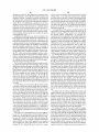
A system for modifying the functionality of intelligent elec
tronic devices installed and operating in the ?eld is disclosed.
(56)
See apphcanon ?le for Complete Search hlstory'
References Cited
Each of the intelligent electronic devices operates With a
software con?guration to monitor electrical energy. A copy of
US. PATENT DOCUMENTS
the software con?gurations may be maintained in a database.
Changes to the operation of one or more of the intelligent
4,225,839 A
9/1980
Martincic .................. .. 336/96
4,377,837 A
3/1983 Matsko et a1. ............. .. 361/105
4,589,075 A
5/1986 Buennagel
4,900,275 A
2/1990 Fasano ..................... .. 439/716
100
electronic devices may be made as a function of modi?cations
tome database"
19 Claims, 12 Drawing Sheets
1°‘
E
|§g|3|
61g
MASTER
Illlll &IED E
E1
Illllll
&
lED
US 7,447,760 B2
Page 2
US. PATENT DOCUMENTS
6,801,920 B1
8/2006
5/2001
1/2002
Forth etal. ............... .. 709/221
Kikinis ..................... .. 709/220
Alnwick .................... .. 705/26
2002/0026385 A1
2/2002
McCloskey etal. ......... .. 705/27
2002/0046246 A1
4/2002 Wright et 31‘
5548527 A
5554312 A
8/1996 Hemmingeretal' ------ -- 364/492
9/ 1996 Ward -------------- -- 510/ 175
2002/0007318 A1
5,555,508 A
9/1996 Munday etal
364/492
.. 364/473.01
5,570,292 A
10/1996 Abraham et a1. ..
5,602,363 A
2/1997
5,627,759 A
5/1997 Bearden etal
VOIIAIX --------------- -- 174/521
5650936 A
5,654,081 A
5,675,748 A
7/1997
8/1997
10/1997
Loucksetal ------------- -- 364/483
Todd -------- -428/209
ROSS -------- -395/284
5,680,640 A
5,704,805 A
10/1997 Ofek er 91
V1998 Douty er a1
395/839
439/532
5,710,887 A
1/1998 Chelliah et al.
5,715,314 A
2/1998
5736847 A
4/1998 Van Doom er a1
5/2002
7/2002 Baker etal.
2002/0169570 A1
2003/0009401 A1
11/2002 Spanieretal. .............. .. 702/61
1/2003 Ellis .......................... .. 705/35
2003/0061335 A1
10/2003
2004/0122833 A1
6/2004
6/1998
9/1998 Gu ........... ..
Jovellana ..... ..
324/117 R
Loucksetal. ..
5,862,391 A
1/1999 Salasetal.
5,880,927
3/1999
Jorgenson ................. .. 713/201
Krichilsky etal. ........... .. 707/3
Christensen etal.
.. 705/26
3/2003 ThomaS et 31‘
Ransom etal.
Forth etal.
FOREIGN PATENT DOCUMENTS
.. 395/750.01
W0
W0 99/13418
W0
WO 00/79452 A2
12/2000
5,896,393 A
4/1999 Yard etal. ............... .. 371/10.2
WO
WO01/01079 A1
1/2001
5,897,607 A
4/1999 Jenney etal.
W0
WO 01/01154 Al
l/200l
5,907,476 A
5/1999 DavidsZ .................... .. 361/732
W0
W0 01/01155 A1
1/2001
5,909,492 A
6/1999 Payne etal.
380/24
WO
WO01/01156 A1
1/2001
5,933,004 A
8/1999 Jackson etal. .
324/142
WO
WO01/01157 A1
1/2001
5,936,971 A
8/1999 Hararietal.
371/10.2
WO
WO01/01159 A1
1/2001
9/1999 Yingeretal. ............. .. 395/712
5,960,204 A
Kent etal.
.....
3/1999
W0
WO 01/01160 A1
l/200l
5,963,734 A
10/1999 Ackerman etal.
395/500.39
WO
WO01/55733 A1
8/2001
5,963,743 A
10/1999 Amberg etal. ............ .. 395/712
W0
W0 01/73651 A2
10/2001
5,978,590 A
11/1999
Imaietal. .... ..
395/712
5,991,543 A
11/1999 Amberg etal. .
395/712
5,994,892
11/1999
324/142
A
5,995,911 A
Turino etal.
........... .. 713/300
............... .. 707/100
..... .. 364/483
. . . . . .. 361/634
A
709/208
8/2002
10/2002
10/2002
2003/0204756 A1
324/142
340/870.02
Baum ........................ .. 705/26
2002/0104022 A1
2002/0152200 A1
2002/0156694 A1
395/226
5,767,790 A
10/1998
2002/0065741 A1
2002/0091784 A1
Payne etal- ----------- -- 380/24
5,811,965 A
5,828,576 A
10/2004 Wischinski
7,085,824 B2
2001/0001866 A1
.............. ..
11/1999 Han
OTHER PUBLICATIONS
_
_
_
_ _
_
PLC Solut1ons SubstatlonAutomatlonTransparentUtlllty,Schneider
6,000,034 A
12/1999 Lightbody etal. ........ .. 713/202
Elect“, Jun 1999,4969
6,008,711 A
0/1999
n 336/92
PLC-based Automatlon Electric Power Process and Substation Con
6,023,160 A
20000
~~_ 324/142
trol
Quick
Products,
Facts Sheet, “6200Electric,
ION Compact Modular Power & Energy
6,049,551 A
4/2000 Hinderksetal. .......... .. 370/468
Meter”,POWeTMeaSurement,11792000,1Page~
6,059,129 A
50000 Bechaz et a1‘ __________ " 211/9401
Brochure, “The First True Breakthrough In Solid-State Residential
6,064,192 A
5/2000
6,078,870 A
6/2000 Windsheimer ............. .. 702/61
Manual’
6,088,659 A
70000 Kelley et a1‘
TransduceriInstallation and Operation Manual, Power Measure
6,091,237 A
7/2000
manta Ltd» 1999791396“
6,092,189 A
7/2000 Fisher et al. ................. .. 713/1
Redmyer ..... ..
.324/127
Chen ........................ .. 324/142
_
_
MetenngTCENTRON®r1998’4P€1geS~
3300
ACM,
Economlcal
_
_ _
Dlgltal
Power
Meter/
_
Brochure’ SENTINEL TM Electro“ “Multlmeasufemem Meter,”
6,144,960 A
11/2000
Okada etal. ................ .. 707/10
Schlumberger, Ma“ 2001’ 4Pages~
6,167,383 A
12/2000
Henson
System Manager Software Setup Gulde, Verslon 31, P~ 37, 1999
6,169,794 B1*
.........
. . . ..
705/26
1/2001 Oshimietal. ........ .. 379/221.09
_
_
Powerlogic System ManagerTM 3000 Software Family’ Square D
6,182,275 B1
1/2001 BeelitZ
Lee et et al. ................ .. 717/1
770°
Schneider
1°11 3-Phase
Electric, Power
Bulletin
Meter,
NO. Analyzer and Controller,
Oct. W 1'8,
6,185,508 B1
2/2001 Van Doorn etal. .......... .. 702/60
18083012009
6,192,470 B1
2/2001 Kelley etal. ................. .. 713/1
7700 ION® User’s Guiderversion 2~(LAPP9I1diX, PP~A1-A& Filed
6,199,068 B1
3/2001 Carpenter
asear1yaS$PP~2L1998~
6,212,278
6,219,656
6,246,994
6,247,128
6,262,672
6,275,168
6,301,527
6,327,706
6,363,057
6,367,023
B1
B1
B1
B1
B1
B1
B1
B1
B1
B2
6,374,084 B1
4/2001
4/2001
6/2001
6/2001
7/2001
8/2001
10/2001
12/2001
3/2002
4/2002
Bacon etal. .............. .. 380/240
Cain et a1, ________________ __ 705/412
Wolven et al. .
.... .. 705/14
Fisher et al. .............. .. 713/100
Brooksby et al. ...... .. 340/870.1
Slater et al. .......... .. 340/870.02
Butland et al. ............ .. 700/286
Amberg et al. .............. .. 717/11
Ardalan et al. .
370/252
Kling et al. ............... .. 713/340
4/2002 FOk ......................... ..
7700ION® Revenue MeterProgramming Key1PP~ l-4,Aug~6, 199?
6200 ION, Installation & Basic Setup Instructions, © Power Mea
SurementLtde Revision Date Apr. 25, 2001, 50 pages.
DSP56F801/803/805/807 16-Bit Digital Signal Processor User’s
Manual PreliminaryiRev. 3.0, © Motorola, Inc., 2001, 782 pages.
1991, Robert Bosch, “CAN Speci?cation Version 2.0”, 68 pages.
A. Lakshimikanth and Medhar M.Morcos, Article “A Power Quality
Monitoring System: ACase Study in DSP-based Solutions for Power
Electronics,” EEE Transactions on Instrumentation and Measure
ment vol. 50 No. 3 Jun. 2001, 8 pages.
Murphy article, Internet Appliance Design “Forget Me Not,”
6,401,054 B1
6,459,175 B1
6,459,997 B1
6/2002 Andersen - 702/179
10/2002 Potega ...................... .. 307/149
10/2002 Andersen ................... .. 702/57
Embedded Systems Programming Jun. 2001, 4 pages.
1ON® Technology, Meter Shop User’s Guide, @ power Measure.
ment Ltd‘, Revision Date May 10, 2001, 48 pages,
6,486,652 B1
11/2002 Ouellette et 31'
- 324/142
Electro Industries/Gauge Tech DM Seriesispeci?cation brochure,
6,493,644 B1
6,496,342 B1
12/2002 Jonker et a1. ................ .. 702/61
12/2002 Horvath et al. .............. .. 361/65
“DMMs 425 L0W_C0St Multifunction Power Monitoring OutPer.
forms
Others in its Class,” 4 pages,
6,687,698 B1
2/2004 NiXOIl et a1~
MotorolaTM Preliminary Information Application Brief “Electronic
6,694,270 B2
6,798,190 B2
2/2004 Hart .......................... .. 702/57
9/2004 Harding et al. ........... .. 324/142
Energywith Powerline Modem on DSP56F80X,” Digital DNAfrom
Motorola, © 2000 Motorola, Inc., 2 pages.
US 7,447,760 B2
Page 3
PM130 Serials TrueMeterTMiThe Low Cost Analog Replacement,
speci?cations, Satec, Inc., 2 pages.
Nexus 1250 Precision Power Meter & Data Acquisition Node, Accu
measure® Technology, Electro Industries/Gauge Tech, speci?cation,
Power Measurement, “7500 ION® User’s Guide,” www.pml.com
1999.
Wally Klingensmith, “Coordination and System Reliability: Choos
ing the Right Software,” http://www.cooperpower.com/Products/
8 pages, date unknown but before Nov. 13, 2003.
Systems/pdf/sysirelyasp, 200 1 .
ION Technology, 7500 ION High Visibility 3-Phase Energy & Power
Quality Meter, Power Measurement, speci?cation, pp. 1-8, revision
John D. RamboZ and Oskars Petersons, “A Calibration Service for
Current Transformers,” U.S. GR 0.: 1991-281-557: 40033.
date Mar. 21, 2000.
F. Momal, J. Brahy, R. Saban, P. Sollander, “Integrating a Commer
cial Industrial Control System to the Accelerator Control System,”
Proc. ICALEPCS 1993 Berlin, p. 464.
Power Measurement, “Multi-Port Communications Card (MPCC),
Multi-Port Ethernet Communications Card (MPE),” Installation and
Operation Instructions, 1997.
Power Measurement, “7500 ION® Installation & Basic Setup
Instructions,” www.pml.com 2000.
R. Saba, P Ciriani, A. Guiard-Marigny, H. Laeger, M. Rabany, A.
Swift, “Equipment Industrially Controlled,” Proc. ICALEPS 1993
Berlin, p. 461.
F. Momal, D. Bienvenu, D. Brahy, D. Lavielle, R. Saban, B.
v206, What’s New in the 7500 ION®,” www.pml.com 2000.
Power Measurement, “7700 ION® Xpress CardTM Installation &
Vuillerme, L. Walckiers, “A Control System based on Industrial
Basic Setup Guide,” www.pml.com.
Power Measurement, “Addendum to the User’s Guide Addendum
Components for Measuring and Testing the Prototype Magnets for
Power Measurement, “7700 ION® 3-Phase Power Meter, AnalyZer
LHC,” Proc. EPAC 94 London, p. 2322.
Web Utility User Manual for Quantum and Premium, 890 USE 152
00 Version 1.0, Groupe Schneider, Oct. 1998, 18 pgs.
and Controller,” www.pml.com 1998.
Power Measurement, “7700 ION® Installation & Operation
Manual,” www.pml.com 1996.
Class 3020 Powerlogic® Power Meter, Square D Groupe Schneider,
Power Measurement, “ION® 8000 Series Meter, Meter Connectiv
Oct. 1998, 4 pgs.
Press Release, Feb. 23, 2000, entitled “Connect One and Nams create
the World’s First Dial-Up Energy Meter that Sends and Receives
E-mail Without A Gateway,” available at http://www.connectone.
ity,” www.pml.com 2001.
pml.com 1999.
com/PressFiles/58ipress.htm, obtained Aug. 17, 2004, 4 pgs.
Online Article, Apr. 26, 2000, entitled “Embedded Systems Confer
tures connect power meters over the Internet,” http://www.pwrm.
ence Provides a Connection to the Web,” available at http://www.
com/company/news/a51.asp 2000.
technoline.com/community/ediresource/featureiarticle/6341,
Power Measurement, “Power Measurement Enhances Web Commu
nications and Security Functions on IOI Energy and Power Quality
obtained Aug. 26, 2004, 3 pgs.
Online Article, Mar. 13, 2000, entitled “Your Electricity Meter Read
Over the Internet by Newsbytes,” available at http://exnca/stories/
2000/03/13/04.asp, obtained Aug. 17, 2004, 2 pgs.
Exemplary Invoices of the 7500 Meter Showing Purchase Order and
Shipping Information, Dec. 16, 1999, 6 pgs.
Jeff Tyson, “How OSI Works,” available at http://computer.
howstuffworks.com/osi.htm/printable, obtained Aug. 27, 2007, 2
PgS~
SCADA, from Wikipedia, the free encyclopedia, available at httpzen.
wikpedia.org/wiki/SCADA, obtained Aug. 27, 2007, 7 pgs.
International Search Report.
F. Momal, C. Into-Pereira, “Using World-Wide-Web for Control
Systems,”AT Division CERN, 1211 Geneva 23.
F. Momal, J. Brahy, R. Saban, P. Sollander, “Integrating a commercial
industrial control system to the accelerator control system: a case
study,” Nuclear Instruments and Methods in Physics Research, A 3 52
(1994) 464-466.
R. Saban, P. Ciriani, A. Guiard-Marigny, H. Laeger, M. Rabany, A.
Swift, “Equipment industrially controlled,” Nuclear Instruments and
Methods in Physics Research, A 352 (1994) 461-463.
F. Mormal, D. Bienvenu, D. Brahy, D. Lavielle, R. Saban, B. Vul
lierme, L. Walckiers, “A Control System based on Industrial Com
Power Measurement, “Technical Documentation, 8500 ION® 8500
ION and 850 ION-PQ Advanced Intelligent Billing Meters,” www.
Power Measurement, “New MeterM@ailTM and WebMeterTM fea
Meters,” http://www.pwrm.com/company/news/a62.asp 2001.
Electro Industries, “User’s Installation & Operation and User’s Pro
gramming Manual,” www.electroind.com 1995.
Power Measurement, “ION® MeterM@il®, Technical Note]7 www.
pwrm.com 2001.
Electro Industries/Gaugetech, “Nexus 1250 Performance Power
Meter & Data Acquisition Node,” www.electroind.com.
Electro Industries/Gaugetech, “Nexus 1250 Installation & Operation
Manual Revision 1.20,” www.electroind.com 2000.
Power Measurement, “7700 IONTM Xpress Card Installation & Basic
Setup Guide,” www.pwrm.com 1997.
Power Measurement, “8400 ION/8500 ION Instructional Lea?et,”
www.pwrm.com 1999.
Electro Industries/Gaugetech, “Futura+ Series, Advanced Power
Monitoring and Analysis for the 21St Century,” www.electroind.com.
Electro Industries/Gaugetech, “Nexus 1250 Precision Power Meter
& Data Acquisition Node,” www.electroind.com 1999.
Power Measurement, “3720 ACM 3-Phase Power Instrumentation
Package,” www.pwrm.com 1998.
Power Measurement, “3720 ACM Installation & Operation Manual,”
www.pwrm.com 2000.
ponents for Measuring and Testing the Prototype Magnets for LHC,”
DranetZ-BMI, Signature System Basics, “Here’s How Signature Sys
CERN-ATCH-1211 Geneva 23.
tem Works . . . ”pp. 1-2, http://www.signaturesystem.com/sigbasics.
R. Saban, D. Brahy, J. Casas-Cubillos, M. Grippeling, D. Lavielle, G.
Leo, L. Madaro, A. Rijllart, M. Skiadelli, “The Control and Data
Acquisition of the LHC Test String,” AT Division CERN, 1211
Geneva 23.
Peter M. Corcoran, Joe Desbonnet, and Karl Lusted, “CEBus Net
work Access via the World-Wide-Web,” IEEE, 1996 236-237.
“Technical Overview Ethernet SCAN IITM Module,” ATI Systems
Inc., Milwaukee, WI 1994.
Press Release, “AT&T forms expert team to design utility industry
html, Copyright 1997, 1998, 1999, 2000 DranetZ-BMI.
DranetZ-BMI. Signature System Infonodes, “Communications
Options,” pp. 1-2, http://wwwsignaturesystem.com/infonode.html,
Copyright 1997, 1998, 1999, 2000 DranetZ-BMI.
G.E. Power Management, enerVista.com, Utility Enterprise Manage
ment, pp. 1-8, http://www.serv02.enervista.com/enervista.pdf, from
brochure Printed in Canada enerVista.com 1t.qrk Jan. 30, 2001.
“GE Power Management enerVista.com opens window to a whole
new world of web-enabled SCADA and substation management
1995.
services,” pp. 1-4, http://www.serv02.enervista.com/;nav/new/
enerVista.pdf, Markham, ON, Sep. 6, 2000.
Newsbytes, “TECO & IBMiThe “Smart House” Is Here,” http://
Engage Networks, Inc., “Internet Protocol Card for Revenue
solutions,” http://www.lucent.com/press/0195/950123.mma.html,
?lebox.vt.edu/users/mikemike/smart-house/infotrac/article4.txt,
Meters,” pp. 1-2, http://www.engagenet.com/datasheets/ipcardpdr.
1995.
Power Measurement, “8500 ION® 8400 ION® Advanced Socket
muNet, Inc. “WebGate Iris (Internet Residential Information Sys
tem,” pp. 1 @ http://www.munet.com/MunetProducts IrisIndex.htm.
“Products (copy),” pp. 1-3 @ http://www.munet.com/
MunetProductsiIrishtm.
Mount Meter,” www.pml.com 1999.
Power Measurement, “7500 ION® 7600 ION® High Visibility
Energy and Power Quality Compliance Meters,” www.pml.com
2000.
“Preliminary Speci?cations” pp. 1-2 @ http://www.munet.com/
MunetProducts IrisSpec.htm.
US 7,447,760 B2
Page 4
muNet, Inc. “WebGate Icis (Internet Commercial Information Sys
tem),” pp. 1 @ http://WWW.munet.com/MunetProducts IcisIndeX.
“Products (WebGate ICIS Internet AMR Now),” pp. 1-2 @ http://
munet.com/muNetNeWPressReleases0205001.htm, Feb. 5, 2001.
muNet, Inc., muNet’s WebGate IRIS Deployed for Utility Trials
Across
US,
pp.
1-2
@http://WWW.munet.com/
muNetNeWPressReleases121300.htm, Dec. 13, 2000.
www.munetcom/MunetProducts Icis.htm.
muNet, Inc., “muNet’s WebGate System Finds a Home on the
Products (WebGate ICIS Control Center Software), pp. 1-2 @ http://
www.munetcom/MunetProducts IcisSpec .htm.
muNet, Inc., “muNet Demonstrates End-to-End IP-Based Energy
Management System at DistribuTECH,” pp. 1-2 @http://WWW.
Internet,”
pp.
1-2
@http ://WWW.munet. com/
muNetNeWPressReleases031899.htm, Mar. 18, 1999.
htm
* cited by examiner
US. Patent
Nov. 4, 2008
Sheet 1 0f 12
US 7,447,760 B2
(10
12
/18
L
16
USER INTERFACE
\
v
/
PROCESSOR :
‘
'
22
MEMORY
k 20
‘
COMM.
PORT
24
\
14
\
NETWORK
FIG. 1
32\
—-|NPUT—>
,- so
MODULE
(34
-OUTPUT>
j
SETUP-J 35
REGISTER
I
FIG. 2
US. Patent
Nov. 4, 2008
Sheet 2 0f 12
US 7,447,760 B2
44
40 \
f- 38
f
—-PULSE 00-»
PULSE —PULSE OUT->
MERGE
——ENABLE—> MODULE ‘P———EVENT—>
42 J
\46
FIG. 3
62
(- 52
INPUT->MODULEA
INPUT
54
I
64
MODULE B——PULSE
PULSE IN IN
AB
/' 58
MODULE
PULSE IN c
66
PULSEI
|NPUT—> MODULE c _|
K 56
OUT/
v
MODULE D /
FIG. 4
60
US. Patent
Nov. 4, 2008
Sheet 3 0f 12
mw>o
A‘
U
2\
Efl8K_u
US 7,447,760 B2
.OEm
US. Patent
Nov. 4, 2008
Sheet 4 0f 12
US 7,447,760 B2
/70
100
104
EEC"
%
ESQ
MASTER IED E
‘ED
||||ll|
82
ESQ
IED
‘
‘
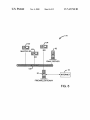
EMAIL SERVER
84
f'
78
x % <—_—> INTERNET
l l l l l l l]
FlREWALL/GATEWAY
FIG. 6
US. Patent
Nov. 4, 2008
US 7,447,760 B2
Sheet 5 0f 12
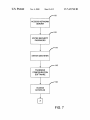
110
ACCESS NETWORK
SERVER
112
V
ENTER SECURITY
PASSWORD
114
ENTER IDENTIFIER
i
116
TRANSFER
CONFIGURATION
SOFTWARE
1
118
ACCESS
DATAFILES
FIG. 7
US. Patent
Nov. 4, 2008
Sheet 6 0f 12
US 7,447,760 B2
122\ [PNO
NOTlFY
USER
YES
124
126
CONTINUE? NO—>@
YES
128}
l
130
V
RECONCILE
MODIFY
DIFFERENCES
'
DATAFILE
132
7
TRANSFER
UPDATE
134
APPLY
UPDATE
FIG. 8
US. Patent
Nov. 4, 2008
Sheet 7 0f 12
US 7,447,760 B2
14Q-\ ADDITIONAL
FUNCTIONALITY
DESIRED
146
142
\ FUNiq'llzglli-AYUTY
\
‘
ETTA/egg:
COMMUNICATIONS
NO
144
IED
CONTAINS
14s\
' RICING?
TRANSFER
YES
NO
‘I
REQUEST &
SOFTWARE
CONFIGURATION
PRICING DATA
TO IED
FIG. 9
US. Patent
Nov. 4, 2008
US 7,447,760 B2
Sheet 8 0f 12
B
l
156
SUPPLY
BRUNG[MUA
158
160
‘UTHENHCATED?
YES
YES
162
TRANSFER
UPDATETO
BlUNG
PROCESS
IED
l
'1 /164
166
IEDUPGRADED
FIG. 10
US. Patent
Nov. 4, 2008
Sheet 9 0f 12
US 7,447,760 B2
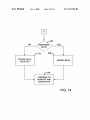
12
A
B
C
170
172\
FIRST IED
SECOND IED
/' 14
NETWORK
MASTER SERVER
NETWORK SERVER
FIG. 11
US. Patent
Nov. 4, 2008
Sheet 10 0f 12
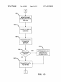
US 7,447,760 B2
180\
INSTALL 2ND IED
I
182\ 2ND IED ESTABLISH
COMMUNICATION
UPDATE 2ND IED
I
PLACE 2ND IED IN
SERVICE
V
TRANSFER DATA
FROM 1 ST IED
REMOVE 1ST IED
FROM SERVICE
FIG. 12
US. Patent
Nov. 4, 2008
Sheet 11 0f 12
US 7,447,760 B2
192
MONITOR AND
STORE DATA WITH
2ND IED
194
l
PLACE 1ST IED IN
SERVICE
196
L
TRANSFER DATA
TO MASTER
SERVER
200 \
198
YES
ADDITIONAL
DATA?
APPEND DATA TO
PREVIOUSLY
STORED DATA
202
TRANSFER DATA
TO 1ST IED
FIG. 13
US. Patent
Nov. 4, 2008
Sheet 12 0f 12
DELETE DATA
RECIEVED
US 7,447,760 B2
APPEND DATA
{
208
CONTINUE TO
+
MONITOR AND
<—---——‘
STORE DATA
FIG. 14
US 7,447,760 B2
1
2
SYSTEMS FOR IN THE FIELD
CONFIGURATION OF INTELLIGENT
ELECTRONIC DEVICES
the ?eld, additional site-speci?c data may be entered to com
plete or modify the con?guration based on the operational
functionality desired.
A typical consumer or supplier of electrical energy may
have many intelligent electronic devices installed and oper
RELATED APPLICATIONS
ating throughout their operations. The intelligent electronic
devices may operate individually, or may operate as part of a
This application is a divisional of US. patent application
Ser. No. 09/792,701, ?led Feb. 23, 2001, now US. Pat. No.
monitoring system. Each of the intelligent electronic devices
may require unique softWare con?gurations, or multiple
7,085,824 B2. The following and commonly assigned US.
devices may include the same softWare con?guration.
patent applications Were ?led on the same date as US. patent
application Ser. No. 09/792,701 , now US. Pat. No. 7,085,824
In the prior art, modi?cation of the softWare con?guration
of previously installed and operating devices may be a tedious
and labor-intensive task. Prior art intelligent electronic
B2. These applications relate to and further describe other
aspects of the embodiments disclosed in the present applica
tion and are herein incorporated by reference.
US. patent application Ser. No. 09/791,340, now US. Pat.
No. 6,853,978, “SYSTEM AND METHOD FOR
devices are recon?gured individually. Individual recon?gu
ration may involve manually inputting data and instruction
sets into the device at the site Where device is installed (e. g.,
in the ?eld). Similarly, in those prior art devices that include
MANUFACTURING AND CONFIGURING INTEL
LIGENT ELECTRONIC DEVICES TO ORDER”, ?led
on Feb. 23, 2001.
US. patent application Ser. No. 09/792,699, now US. Pat.
No. 6,671,635, “SYSTEMS FOR IMPROVED MONI
20
number of intelligent electronic devices, the length of time
required to perform the revisions greatly increases. Further,
TORING ACCURACY OF INTELLIGENT ELEC
TRONIC DEVICES”, ?led Feb. 23, 2001.
US. patent application Ser. No. 09/791,421, now US. Pat.
No. 7,249,265, “MULTI-FEATURED POWER
METER WITH FEATURE KEY”, ?led Feb. 23, 2001.
25
30
BRIEF SUMMARY
This invention relates to systems for monitoring electrical
energy in electrical distribution systems, and more particu
The present invention is de?ned by the folloWing claims,
larly to systems for recon?guring and upgrading the softWare
con?guration in previously installed and operating intelligent
electronic devices.
2. Description of the Related Art
and nothing in this section should be taken as a limitation on
35
ments described beloW include a system for modi?cation of
Monitoring of electrical energy by consumers and provid
electric poWer distribution system. Electrical energy may be
those claims. By Way of introduction, the preferred embodi
the softWare con?guration of ?eld-installed intelligent elec
ers of electric poWer is a fundamental function Within any
monitored for purposes of usage, equipment performance and
poWer quality. Electrical parameters that may be monitored
include volts, amps, Watts, vars, poWer factor, harmonics,
kilowatt hours, kilovar hours and any other poWer related
measurement parameters. Typically, measurement of the
maintaining a record of the current softWare con?guration of
an intelligent electronic device may be dif?cult. Accordingly,
a need exists for systems capable of performing ef?cient
modi?cation of the softWare con?guration of multiple intel
ligent electronic devices and maintaining a record of the
current softWare con?gurations.
BACKGROUND
1. Field of the Invention
remote communication via a modem, each intelligent elec
tronic device must be individually contacted and changes to
the con?guration initiated via the modem connection. Where
it is desirable to revise the softWare con?guration of a large
40
tronic devices. As used herein, the term “?eld” should be
construed to mean the site Where the intelligent electronic
device is installed and operates to monitor electrical energy
folloWing purchase by a user.
An intelligent electronic device (IED) is operated With a
softWare con?guration. A copy of the softWare con?guration
is maintained in a database. The database is accessible With a
45
netWork. The intelligent electronic device may communicate
voltage and current at a location Within the electric poWer
distribution system may be used to determine the electrical
over the netWork. A server or other central processing unit
parameters for electrical energy ?oWing through that loca
device and the database is also coupled With the netWork. The
(CPU) in communication With the intelligent electronic
tion.
Devices that perform monitoring of electrical energy may
server provides a virtual meter site Where modi?cations to the
50
functionality of the intelligent electronic device may be per
be electro-mechanical devices, such as, for example, a resi
dential billing meter or may be intelligent electronic devices
formed over the netWork using the database. Modi?cations
performed at the server may be packaged as an update and
(“IED”). Intelligent electronic devices typically include some
transferred over the netWork to one or more of the intelligent
form of a processor. In general, the processor is capable of
using the measured voltage and current to derive the measure
electronic devices in an automated fashion. The updates
55
ment parameters. The processor operates based on a softWare
con?guration.
The softWare con?guration is typically instruction sets
stored in the intelligent electronic device. The instruction sets
may be softWare, ?r'mWare or some other form of operating
code and includes device speci?c data used to con?gure a
One embodiment describes a method of modifying the
operation of an intelligent electronic device installed in the
60
ligent electronic device is determined during manufacturing.
FolloWing installation of the intelligent electronic device in
?eld. The method comprises operating the intelligent elec
tronic device With a softWare con?guration to monitor elec
trical energy. The method further comprises accessing a vir
tual meter site via a netWork and selecting modi?cations for
the softWare con?guration With the virtual meter site. In addi
particular intelligent electronic device. The softWare con?gu
ration of an intelligent electronic device is used during moni
toring of the electrical energy and the derivation of measured
parameters. Typically, the softWare con?guration of an intel
received by the intelligent electronic devices may be applied
to the softWare con?guration currently operating in the intel
ligent electronic devices.
65
tion, the method comprises revising the softWare con?gura
tion With the virtual meter site as a function of the selected
modi?cations.
US 7,447,760 B2
3
4
Another embodiment describes a method of modifying the
con?guration of an intelligent electronic device installed in
BRIEF DESCRIPTION OF SEVERAL VIEWS OF
THE DRAWINGS
the ?eld. The method comprises operating the intelligent
electronic device With a ?rst softWare con?guration to moni
tor electrical energy. In addition, the method comprises com
softWare con?guration stored in a database and generating a
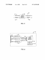
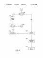
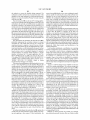
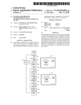
FIG. 1 is a block diagram of a portion of a poWer distribu
tion system that includes one embodiment of an intelligent
electronic device.
FIG. 2 depicts an exemplary embodiment of a module
?rst softWare revision as a function of the modi?cation. The
operating Within the intelligent electronic device illustrated in
method further comprises initiating the transfer of the ?rst
FIG. 1.
municating over a netWork to modify a copy of the ?rst
FIG. 3 depicts another exemplary embodiment of a module
softWare revision over the netWork to the intelligent elec
tronic device and updating the ?rst softWare con?guration
operating Within the intelligent electronic device illustrated in
With the ?rst softWare revision to create a second softWare
FIG. 1.
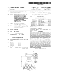
FIG. 4 depicts an exemplary embodiment of a framework
con?guration. In addition, the method comprises operating
the intelligent electronic device With the second softWare
con?guration to monitor electrical energy.
Yet another embodiment describes a method of modifying
the functionality of a plurality of intelligent electronic devices
installed and operating in the ?eld. The method comprises
that includes the modules depicted in FIGS. 2 and 3.
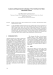
accessing a virtual meter site via a netWork and specifying an
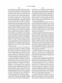
portion of a netWork distribution system that includes the
intelligent electronic device illustrated in FIG. 1.
identi?er for the intelligent electronic devices. The method
further comprises initiating the creation of an update to a
FIG. 5 is a block diagram of one embodiment of a portion
of a netWork distribution system that includes the intelligent
electronic device illustrated in FIG. 1.
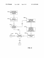
FIG. 6 is a block diagram of another embodiment of a
20
FIG. 7 is a ?rst part of one embodiment of a How diagram
illustrating operation of the netWork distribution systems
softWare con?guration of each of the intelligent electronic
devices With the virtual meter site and transferring the update
25
illustrated in FIGS. 5 and 6.
FIG. 8 is a second part of the How diagram of FIG. 7.
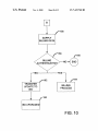
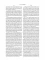
FIG. 9 is a ?rst part of another embodiment of a How
ration in each of the intelligent electronic devices With the
diagram illustrating operation of the netWork distribution sys
update.
30
tems illustrated in FIGS. 5 and 6.
FIG. 10 is a second part of the How diagram of FIG. 9.
FIG. 11 is a block diagram of another embodiment of a
portion of a poWer distribution system that includes embodi
35
ments of the intelligent electronic device.
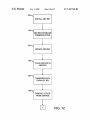
FIG. 12 is a ?rst part of a flow diagram illustrating opera
tion of the intelligent electronic devices illustrated in FIG. 11.
FIG. 13 is a second part of the How diagram of FIG. 12.
FIG. 14 is a third part ofthe ?oW diagram of FIG. 12.
to the intelligent electronic devices over the network. In addi
tion, the method comprises modifying the softWare con?gu
A method of adding functionality to an intelligent elec
tronic device installed and operating in the ?eld is described
by another embodiment. The method comprises specifying
functionality to be added to the intelligent electronic device
With a user interface and selecting payment for the function
ality using the user interface. The method further comprises
upgrading the functionality of the intelligent electronic
device.
Another embodiment describes a method of maintaining
the integrity of data collection in an intelligent electronic
device operating in the ?eld to monitor electrical energy. The
DETAILED DESCRIPTION OF THE PREFERRED
EMBODIMENTS
method comprises operating a ?rst intelligent electronic
device and a second intelligent electronic device at a location
40
to monitor electrical energy. The method further comprises
transferring data collected by the ?rst intelligent electronic
intelligent electronic devices that are installed in the ?eld. The
modi?cation may be performed on an individual intelligent
device over a netWork to a database and terminating the
electronic device. In addition, groups of intelligent electronic
operation of the ?rst intelligent electronic device to perform
maintenance of the ?rst intelligent electronic device. In addi
The presently preferred embodiments disclose a system for
performing modi?cation of the softWare con?guration of
45
devices may be identi?ed for modi?cation. Further, a copy of
tion, the method comprises activating the ?rst intelligent elec
the softWare con?guration of the intelligent electronic
tronic device folloWing the maintenance to monitor electrical
energy at the location and transferring data collected by the
second intelligent electronic device to the database. Further,
the method comprises transferring data from the ?rst intelli
gent electronic device and data from the second intelligent
devices may be maintained in a database. Upgrades or
50
Conversely, changes at the intelligent electronic device may
electronic device over the netWork from the database to the
?rst intelligent electronic device.
A system for modifying the functionality of an intelligent
electronic device previously installed in the ?eld and operat
ing is disclosed by another embodiment. The system com
55
prises a server computer, an intelligent electronic device and
a storage device. The intelligent electronic device is in com
munication With the server over the netWork. The intelligent
electronic device is operated With a softWare con?guration
stored therein. The storage device is also in communication
60
With the server. The data storage device comprises a database.
A copy of the softWare con?guration is stored in the database.
The server modi?es the operation of the intelligent electronic
device as a function of modi?cations to the database.
Further aspects and advantages of the invention are dis
cussed beloW in conjunction With the preferred embodiments.
changes to the softWare con?guration of an intelligent elec
tronic device may be performed With the database folloWed
by transfer of the changes to the intelligent electronic device.
be transferred to the database.
FIG. 1 illustrates a block diagram representation of an
embodiment of a portion of a poWer distribution system 10.
The poWer distribution system 10 includes a plurality of con
ductors 12, a netWork 14 and at least one intelligent electronic
device (IED) 16. The conductors 12 and the netWork 14 may
be connected With the IED 16 as illustrated. As used herein,
the term “connected” or “coupled” may mean electrically
connected, optically coupled or any other form of coupling
alloWing the How of data, electricity or some representation
thereof betWeen devices and components that are connected
or coupled. The conductors 12 may be, for example, electric
transmission lines, electric distribution lines, poWer cables,
65
bus duct or any other material capable of conducting electri
cal energy. The conductors 12 are operable to alloW the How
of electrical energy therethrough. The conductors 12 are illus
US 7,447,760 B2
5
6
tratively depicted in FIG. 1 in a three-phase circuit con?gu
ration; however the phase con?guration is not limited to
the processor 20. The processor 20 and the memory 22 coop
three-phases.
for the IED 16.
The network 14 may be the Internet, a public or private
intranet, an extranet, or any other network con?guration to
The memory 22 may be a non-volatile memory, such as for
example a ?ash memory device or other similar memory
enable transfer of data and commands. An example network
con?guration uses the Transport Control Protocol/Internet
storage device in communication with the processor 20. The
memory 22 may store the electrical parameters derived by the
IED 16 during operation. The memory 22 may also store the
software con?guration of the IED 1 6. In addition, the memory
22 may be used to store other information pertaining to the
functionality or operation of the IED 16 or the network 14.
In another embodiment, the memory 22 may include both
non-volatile memory and volatile memory. The memory 22
may store a ?rst portion of the software con?guration in the
non-volatile memory and a second portion of the software
con?guration in volatile memory. In this embodiment, the
eratively operate to form the central processing unit (CPU)
Protocol (“TCP/IP”) network protocol suite, however, other
Internet Protocol based networks are contemplated. Commu
nications may also include IP tunneling protocols such as
those that allow virtual private networks coupling multiple
intranets or extranets together via the Internet. The network
14 may support application protocols, such as, for example,
telnet, POP3, Mime, HTTP, HTTPS, PPP, TCP/IP, SMTP,
proprietary protocols, or any other network protocols known
in the art. During operation, the IED 16 may communicate
using the network 14 as will be hereinafter discussed.
The IED 16 may be a programmable logic controller
(PLC), a remote terminal unit (RTU), an electronic power
meter, a protective relay, a fault recorder or other similar
volatile memory may be is used to limit the amount of more
costly non-volatile memory required. The ?rst portion of the
20
intelligent device installed in the ?eld and capable of moni
toring electrical energy. In addition, the IED 16 may perform
other functions such as, for example, power distribution sys
tem protection, management of power generation, manage
ment of energy distribution and management of energy con
sumption. In one embodiment, the IED 16 includes a user
interface 18, a processor 20, a memory 22 and a communica
tion port 24 connected as illustrated in FIG. 1. It will be
appreciated that the IED 16 may include other hardware
components such as, for example, metering sensors, power
25
In the presently preferred embodiments, the software con
?guration includes ?rmware software and applications soft
30
supplies, signal processing circuits, logic circuits or any other
hardware useful in performing electrical energy monitoring.
As used herein, the term “IED” may be used interchangeably
with the term “IEDs.” For example, the term “IED” may be
used to discuss aspects involving one IED 16 and “IEDs” may
35
be used to discuss aspects involving multiple IEDs 16.
During operation of the power distribution system 10, the
IED 16 monitors the electrical energy ?owing within the
conductors 12. The IED 16 may process the electrical energy
to derive, store and display data for various electrical param
eters indicative of the electrical energy ?owing in the conduc
tors 12. The IED 16 may also provide outputs to, and receive
40
?guration. As will be hereinafter described, the software con
?guration within the IED 16 may be modi?ed remotely with
out removing the IED 16 from service. In addition, the
software con?guration may be modi?ed locally using the user
interface 18.
16. Standard applications software typically performs the
more usual and customary functions for which the IED 16 is
Custom applications software includes those applications
speci?cally tailored to the needs of an end user, or group of
50
end users operating the IED 16 in the ?eld. Any applications
software that is not “off the shelf’ software may be consid
ered custom applications software. Custom applications soft
ware may be developed by the end users, third parties or by
55
As such, the user interface 18 may provide display of the
electrical parameters derived by the processor 20. In addition,
commands for the processor 20 may be entered using the user
the manufacturer of the IED 16.
In the one embodiment, the applications software may be
organiZationally described as a plurality of frameworks. The
frameworks may be an object oriented software architecture
allowing the organiZation of the various operations per
interface 18.
formed by the IED 16. Accordingly, each of the frameworks
60
in a software con?guration may represent one or more parts of
65
the applications software. For example, a framework identi
?ed as a setpoint framework may contain operating instruc
tions for the IED 16 pertaining to setpoints for the various
electrical parameters derived by the IED 16. Other exemplary
frameworks may include, a historic data logging framework,
an electronic control unit or any other device capable of
executing instructions, monitoring electrical inputs and pro
viding electrical outputs. The processor 20 may perform cal
culations, operations and other logic related tasks to operate
the IED 16. In one embodiment, the processor 20 may operate
as a function of the software con?guration. The software
con?guration may be stored in the memory 22 connected with
ware programs designed to derive, display, utiliZe and
manipulate the data within the IED 16. Applications software
may include measurement and recording applications, deri
vation applications, measurement and control applications,
communications applications and any other applications pro
viding functionality to the IED 16. The applications software
may also include standard applications software and custom
designed.
levers, switches, display screens, keypads, touch screens or
The processor 20 may be, for example, a microprocessor,
?rmware may be referred to as an operating system of the IED
16. The ?rmware may include standard as well as optional
components to support the basic functions of the IED 16.
The applications software may include one or more soft
that may be provided as standard functionality within the IED
45
The user interface 18 may include one or more buttons,
any other device(s) capable of providing an interface to a user
of the IED 16. As illustrated in FIG. 1, the user interface 18 is
connected with, and acts as an interface to, the processor 20.
ware. Firmware is the low level operating code providing the
basic functionality, or operating capability of the IED 16. The
applications software. Standard applications software
includes those applications developed by the manufacturer
inputs from, the power distribution system 10. Processing
within the IED 16 may be performed with a software con
software con?guration may include instructions that instruct
the IED 16 to retrieve the second portion of the software
con?guration from another location. As such, when power is
applied to activate the IED 16, the instructions in the non
volatile memory are executed and the remaining software
con?guration is transferred from the remote location (as later
discussed) to the non-volatile memory.
a harmonic measurement framework, a display framework, a
digital inputs framework, an alarm framework, a revenue
US 7,447,760 B2
7
8
framework or any other framework representing some por
another module within the frameworks or may be an external
tion of the functionality of the IED 16.
The software con?guration of this embodiment may be
comprised of the ?rmware and the frameworks. The frame
works may represent both applications software, referred to
as “Core” frameworks, and custom applications software,
output from the IED 16. The processing of the pulse input
signals may be functions such as, for example, anAND, OR,
NOT, or any other Boolean function. In addition, the PM
module 38 may further process the pulse output signals to
generate an event output signal on an event output line 46. The
event output signal may, for example, be written to an event
log or trigger further processing in the IED 1 6. In this embodi
ment, the PM module 38 does not require con?guration set
tings and therefore no setup register lines are included.
FIG. 4 is an exemplary embodiment of a portion of a
framework 50 within the IED 16 (FIG. 1). The framework 50
referred to as “Custom” frameworks.Accordingly, the IED 16
is a highly customizable device capable of performing a wide
variety of monitoring and power management functions.
While the IED 16 may utilize the object oriented framework
architecture, it will be appreciated that the applications soft
ware may also be developed in non-object oriented format
and still provide a highly customizable device.
includes a Module A 52, a Module B 54, a Module C 56, a
Pulse Merge (PM) Module 58 and a Module D 60 that are
connected as illustrated. The Modules A-D 52, 54, 56, 58 are
similar to the module 30 previously discussed with reference
to FIG. 2. In addition, the PM Module 58 is similar to the PM
module 38 previously discussed with reference to FIG. 3.
Each of the frameworks of one embodiment includes a
plurality of modules. The modules may operate within an
object oriented software construct known as an integrated
object network (IONTM) that will be hereinafter discussed.
Development of a framework may be accomplished by link
ing several modules together. The modules may represent
logic tasks performed to manipulate, derive, store, transfer or
otherwise process data. The data input to the modules may be
received by the framework from data inputs to the IED 16, or
20
input line 62 for input signals. During operation, if one of the
input signals reaches a pre-set value, the corresponding Mod
may be the data output from another framework. An IED 16
may have several frameworks operating independently or in
combination with other frameworks to perform various man
ule 52, 54, 56 may output an output pulse signal on a corre
sponding output line 64. The PM module 58 may monitor the
25
agement, control, derivation, storage communication and/or
other functions of the IED 16. In one embodiment, the frame
works may be created in a software design tool called “IONTM
Designer.” “IONTM Designer” is a component of a PEGA
SYSTM software system manufactured by Power Measure
ment Ltd., located in Saanichton, BC, Canada.
FIG. 2 depicts an example of a module 30 operating within
a framework (not shown) of the IED 16 (FIG. 1). The module
30
35
are dependent on the function of the module 30. The setup
register inputs 36 may include con?guration settings for the
module 30. The con?guration settings determine how the
module 30 processes the data received on the inputs 32 and
generates data on the outputs 34.
The module 30 may be designated to perform any of a
number of functions within one of the frameworks. For
example, the module 30 may be an Arithmetic Module that
performs mathematical and logical functions such as multi
plication, addition, square root, etc. to data supplied on the
inputs 32 and provides the result on the outputs 34. Further
examples may include a Display Module that allows for the
creation of custom front panel display screens and a Sag/
40
Swell Module that monitors the voltage inputs for distur
50
45
ule con?gurations are possible.
In the presently preferred embodiments, the frameworks
may utilize the data generated by other frameworks within the
IED 16, or external signals provided to the IED 16, to produce
useful results and/or perform useful functions. Frameworks
ultimately create and allow manipulation of the functionality
of the IED 16. The ease of creation and manipulation permits,
as well as promotes, customization and expansion of the IED
16. As such, the functionality of the IED 16 may be modi?ed
by simply changing or adding frameworks to the device.
The highly customizable and con?gurable nature of the
IED 16 lends itself to solutions satisfying the speci?c needs of
a user’s power management applications. However, this
options and software. Further, the capabilities of the IED 16
make it almost impossible to predict the functionality desired
by each user. It is therefore desirable to provide a system
through which a customer can customize, edit and update the
turbance into discrete components to perform a more detailed
software con?guration of one or more IEDs 16 that are pre
55
viously installed and operating in the ?eld.
The IEDs 16 may also include an identi?er to uniquely
identify each of a plurality of IEDs 16 (not shown). Altema
tively, the identi?er may uniquely identify a predetermined
60
group of IEDs 16. Further, an IED 16 may include a number
of identi?ers both for unique identi?cation as well as for any
number of predetermined groups. The identi?ers may, for
example, be an identi?cation number, such as, a serial number
or a part number. Alternatively, the identi?ers may be letters,
IED 16, or from one or more other modules (not shown). The
PM module 38 may commence with processing the pulse
input signals upon receipt of an enable signal on an enable
line 42. Following processing, the PM module 38 may pro
vide at least one pulse output signal on at least one pulse
output line 44. The pulse output signals may be an input to
Module D 60 may be an Alert Module con?gured to provide
an electrical signal alerting that a maximum value has been
reached. It should be realized that the above-described exem
plary embodiment is merely one example of a portion of one
requires the user of the IED 16 to con?gure and tailor the
frameworks to their needs. It would be impractical for the
manufacturer to offer every conceivable combination of
bances and, upon detection of a disturbance, breaks the dis
analysis. Further exemplary modules of one embodiment
may be found in an “IONTM Reference Manual”, printed by
Power Measurement Ltd., located in Saanichton, BC,
Canada.
FIG. 3 is an exemplary embodiment of a Pulse Merge (PM)
Module 38 operating within a framework (not shown) of the
IED 16 (FIG. 1). The PM module 38 receives at least one
pulse input signal on at least one pulse input line 40. The pulse
input signals may be from an external input (not shown) to the
output lines 64, and upon receipt of one of the output pulse
signals may generate an output pulse signal on an output pulse
line 66. Module D 60 may monitor the output pulse line 66.
framework and numerous other frameworks as well as mod
30 includes at least one input 32, at least one output 34 and at
least one setup register input 36. The quantity and signal type
of the inputs 32, the outputs 34 and the setup register inputs 36
In the exemplary embodiment, Modules A, B and C 52, 54,
56 may be Maximum Modules each con?gured to monitor an
65
numbers or a combination of both. The manufacturer may
determine the identi?ers for an IED 16 or a predetermined
group of IEDs 16. Alternatively, a user may develop identi?
ers following installation in the ?eld.