1
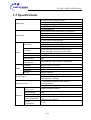
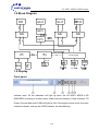
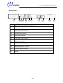
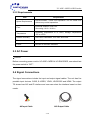
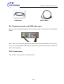
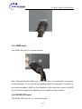
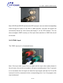
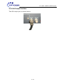
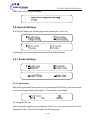
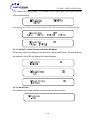
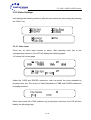
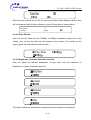
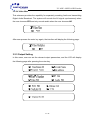
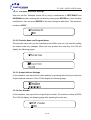
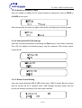
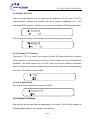
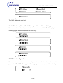
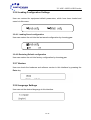
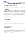
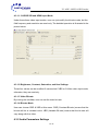
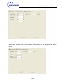
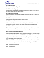
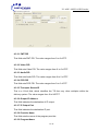
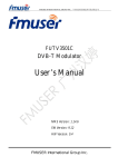
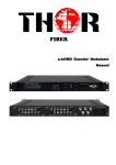
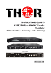
UC-450E+ MPEG-4 HD/SD Encoder User Manual Version: 07302012-01 CONTENTS UC-450E+ MPEG-4 HD Encoder ..................................................................................................... 0 Chapter 1 Product Outline................................................................................................................ 1 1.1Outline ......................................................................................................................................... 1 1.3 Specifications.............................................................................................................................. 2 1.4 Block Diagram..................................................................................................................... 3 Chapter 2 Installation Guide............................................................................................................. 6 2.2 Installation Preparation............................................................................................................... 6 2.3 Signal Wire Connections ............................................................................................................ 7 Chapter 3 Operations ......................................................................................................................11 3.1 Initialization.........................................................................................................................11 3.2.2 Video Settings ................................................................................................................ 14 3.2.4 Network Settings ............................................................................................................ 19 3.2.5 Saving Configuration...................................................................................................... 20 3.2.6 Loading Configuration Settings...……………………………………………………………21 Chapter 4 NMS Operation.............................................................................................................. 22 4.1 Installation................................................................................................................................. 22 4.2 Software Operation................................................................................................................... 22 4.3 UC-450E+ MPEG-4 HD ENCODER Operation ....................................................................... 28 Chapter 5 Troubleshooting ............................................................................................................. 37 Chapter 6 Packing List……………………………………………………………………………………38 UC-450E+ MPEG-4 HD Encoder Chapter 1 Introduction 1.1 Introduction UC-450E+ MPEG-4 HD Encoder uses the advanced AVC/H.264 audio encoding algorithm, combined with Upcom advanced audio and video pre-processing technology. This unit can encode audio & video with high quality at low bit-rates. It has analog and digital video input interfaces (CVBS, YPbPr, SDI, and HDMI), and audio input interfaces (RCA, XLR, HDMI, AES and EUB). Its highly integrated and cost effective design gives users excellent digital video encoding solution, and makes it widely used in Satellite and Terrestrial digital TV Contribution and Broadcasting. 1.2 Features AVC/H.264 High Profile Level 4.0 video encoding support and advanced video pre processing algorithms. MPEG-1 Audio Layer II, and LC-AAC audio encoding algorithm; LC-AAC audio format optional; UDP media transmission protocols & unicast/multicast output support CVBS, S-VIDEO, HD-SDI and YPbPr analog video input interfaces HDMI and SDI digital video input XLR, RCA, AES/EBU analog digital audio input PAL and NTSC SD video formats The resolution formats is 1080P, 1080I, 720P, etc. LCD/keyboard control method. NMS monitoring 1 / 36 UC-450E+ MPEG-4 HD Encoder 1.3 Specifications Video input Audio input Resolution Encoding Video Audio Bit-rate Rate Control GOP Structure CBR/VBR IBBP Advanced Pretreatment De-interlacing, noise reduction, sharpening Encoding Sampling rate MPEG-1 Layer 2, LC-AAC 48KHz Resolution Bit-rate 24-bit 64Kb/s~384Kb/s 2×ASI outputs, BNC interface SPTS over UDP, 10/100Base-T Ethernet interface (UDP unicast / multicast) LCD/keyboard operating, NMS support Control interface Ethernet software upgrade Stream output System function General 1 × Analog CVBS, BNC interface 1 ×S-Video Analog YPbPr input, BNC interface 1 × YPbPr video input, BNC interface 1 x HD/SD-SDI, BNC interface 1 x HDMI interface Analog stereo audio (balanced), XLR interface Analog stereo audio (unbalanced), BNC interface AES / EBU digital audio, XLR interface HD/SD-SDI embedded audio LC-AAC audio format optional 1920x1080_60p, 1920×1080_60i, 1920×1080_50i 1280×720_60p, 1280×720_50p 720×480_60i(NTSC), 720×576_50i(PAL) AVC/H.264 High Profile Level 4.0 for HD AVC/H.264 High Profile Level 3.0 for SD 0.8Mbps~20Mbps Dimensions (W × D × H) Approx weight Temperature range Power requirement Power consumption 482mm×455mm×44.5mm 8 Kg 0~45℃(Operation), -20~80℃(Storage) AC110V±10%, 50/60Hz AC 220V±10%,50/60Hz 17.6W 2 / 36 UC-450E+ MPEG-4 HD Encoder 1.4 Block Diagram 1.5 Display Front panel: Indicator area: All the indicators will light up when the UC-450E+ MPEG-4 HD ENCODER is working in current mode. Under normal conditions, Power indicator, TS Output, Encode Start and CVBS will light up. But if the signal source is lost, the input interface indicator, such as the CVBS indicator, will start blinking. 3 / 36 UC-450E+ MPEG-4 HD Encoder 1. LCD display screen Power:Unit is working TS output:Output stream is TS SD/HD:SD/HD signal indicator Encode Start:The unit starts to encode Encode Error:The unit has encoding error 2. Indicator LED CVBS :CVBS input indicator S-VIDEO:S-VIDEO input indicator YPbPr:YPbPr input indicator HDMI:HDMI input indicator HD/SD-SDI:SDI input indicator 3. Up/Down/Left/Right Arrow 4. Enter:Confirmation key 5. Menu:Menu key 6. Lock:Lock key 4 / 36 UC-450E+ MPEG-4 HD Encoder Rear panel: 7 8 9 10 11 12 13 14 7. Digital audio input interface: AES/EBU, XLR 8. CVBS input interface 9. HD/SD-SDI input interface 10. S-VIDEO input interface 11. YPbPr input interface 12. Analog audio input interface 13. HDMI input interface 14. Two ASI output interfaces 15. 10M/100M Ethernet interface 16. AC Power switch and input 17. Ground 5 / 36 15 16 17 UC-450E+ MPEG-4 HD Encoder Chapter 2 Installation Guide 2.1 Product Checklist After opening the package of the unit, check items according to the packing list. It should include the following items: UC-450E+ MPEG-4 HD Encoder User Manual Analog Audio/Video Composite Input Cables Power Cord If any item is missing or not matching with the list above, please contact your supplier. 2.2 Installation Preparation When installing the unit, please follow the steps below: Check for missing product or damaged product during transportation Set up the right environment for installation Install the Encoder Connect input and output signal cables Connect communication port (if necessary) 6 / 36 UC-450E+ MPEG-4 HD Encoder 2.2.2 Requirements Item Space Requirements Floor Requirement Recommended 1 Rack Unit Separation. Do not Install units without any vertical separation. Electrical Isolation, Dust Free Grounding: 1X10⁷~1X10¹⁰ Temperature Operating Temperature: 0º to +45ºC, Storage Temperature: -25º to +55ºC. Relative Humidity 20%~80% sustainable, 10%~90% short time Pressure 86~105KPa Power 85VAC to 265VAC 50/60Hz 2.3 AC Power Caution: Before connecting power cord to UC-450E+ MPEG-4 HD ENCODER, user should set the power switch to “OFF”. 2.4 Signal Connections The signal connections include the input and output signal cables. The unit has five possible input choices: CVBS, S-VIDEO, YPbPr, HD/SD-SDI and HDMI. The output TS stream has ASI and IP interface and user can select the interface based on their needs. AV Input Cable ASI Output Cable 7 / 36 UC-450E+ MPEG-4 HD Encoder HDMI Cable YPbPr Cables 2.4.1 Unbalanced audio and CVBS video input The encoder’s Analog Composite Video input port and its connections are illustrated below: Note: User must select the appropriate video mode in the Input Section of Unit menu. If not, the encoding video mode will not match to the input source format, and the unit will not work properly. 2.4.2 S-video input The S-video input port is illustrated below: 8 / 36 UC-450E+ MPEG-4 HD Encoder 2.4.3 HDMI Input The HDMI input port is illustrated below: Note: After selecting the HDMI input in the unit menu, it is unnecessary to manually set the resolution, for the unit will automatically identify the resolution. Currently, the unit cannot recognize 1080P, so if the resolution of the video input source is 1080P, the unit will not recognize the signal source, and might not work correctly. 2.4.4 HD/SD-SDI Input The HD/SD-SDI input port is illustrated below: 9 / 36 UC-450E+ MPEG-4 HD Encoder Note: HD SDI and SD SDI use the same SDI input port, user can select corresponding mode through the menu on the LCD or NMS operation, and then the system will automatically detect the video format and display it on the LCD interface. The unit does not support 1080P currently, so if the input video resolution is 1080P, the unit will not encode. 2.4.5 YPbPr Input The YPbPr input port is illustrated below: Note: If the input video format does not match with the input video mode selected in the unit menu, the unit will not encode or will give an encoding error. If the Y input port is not connected, the unit might not detect the input signal; and also the Pr and Pb input ports must be connected to their corresponding ports; if not, the program color may be abnormal. 10 / 36 UC-450E+ MPEG-4 HD Encoder 2.4.6 ASI Output Interface The ASI output port is shown below: 11 / 36 UC-450E+ MPEG-4 HD Encoder Chapter 3 Operations UC-450E+ MPEG-4 HD ENCODER’s front panel is the user operations interface. The detailed operation is described below. Keyboard Function Description: LOCK: Locking the screen / cancelling the lock state, and entering the main menu after initialization of the unit. After pressing the lock key, the system will ask the user whether to save the present settings or not. If not, the LCD will display the current configuration. MENU: Canceling presently entered value, resuming previous setting; Return to previous menu. ENTER: Selecting the parameters to be modified or confirming a change after modification. LEFT/RIGHT: choosing and setting the parameters. UP/DOWN: Modifying selected parameter or scrolling up/down when parameter is not selected. 3.1 Initialization After switching on the encoder, the LCD interface will display the UPCOM name and model, and the current data rate at the first row while the video input and resolution will be at the second row as shown below: Alarm information will be shown as below when there is an input signal loss or the 12 / 36 UC-450E+ MPEG-4 HD Encoder video input is an unsupported signal. 3.2 General Settings The LCD will display the following page after pressing the “Lock” key. At all display, the current option selected is shown within brackets. 3.2.1 Audio Settings 3.2.1.1 Audio Input After entering the Audio Input submenu by pressing the ENTER key, user can choose one of the following three audio inputs; 1/1/ means the current page 3.2.1.2 Audio Bit-rate After entering the submenu by pressing the “Enter” key, user can choose one of of the following bit-rates; The LCD will display the following page. 13 / 36 UC-450E+ MPEG-4 HD Encoder “1/2” means the current page. The number on the upper right is the total effective output audio bit-rate. By pressing the “Enter” key in this interface, the LCD will display the following page: 3.2.1.3 Audio Fs, Audio Format and Audio ES Mode These three items are read-only and the user cannot modify them. So after entering the submenu, the LCD will display the following pages: 3.2.1.4 Audio Gain The default value is 0db, and the submenu goes as shown below: 14 / 36 UC-450E+ MPEG-4 HD Encoder 3.2.2 Video Settings Unit displays the following submenu after the user enters the video setting by pressing the “Enter” key. 3.2.2.1 Video Input There are six video input formats to select. After pressing enter key to the corresponding submenu, the LCD will display the following pages: 1/2 means the current page Under the CVBS and SVIDEO submenus, user can select the video standard by pressing enter key. The choice of Video Standards in CVBS and SVIDEO submenus is displayed below: When users enter the YPbPr submenu by pressing the enter key, the LCD will then display the following page: 15 / 36 UC-450E+ MPEG-4 HD Encoder When the user selects any of the two choices of Frame Rate displayed above, they will be presented with another submenu to select Resolution as shown below: Resolution [1080P] 1/1 [1080I] 3.2.2.2 Video Bit-rate User can set the video bit rate (0.8Mbps to 30Mbps adjustable range) here. After setting, user can see the real-time rate change on the screen. The number on the upper right is the total effective video bit-rate 3.2.2.3 Brightness, Contrast, Saturation and Hue User can adjust the relevant parameters of input video with the submenus of Brightness, Contrast, Saturation and Hue. The figure outside the parentheses is decimal while the inside is hexadecimal. 16 / 36 UC-450E+ MPEG-4 HD Encoder 3.2.2.4 Video Mux This submenu provides the capability for separately encoding Audio and transmitting Digital Audio Broadcast. The system will encode the AV signal synchronously when the user chooses YES and only encode audio when the user chooses NO. After user presses the enter key again, the interface will display the following page: 3.2.3 Output Setting In this menu, user can set the relevant output parameters, and the LCD will display the following page after pressing the enter key. 17 / 36 UC-450E+ MPEG-4 HD Encoder 3.2.3.1 Transport Stream ID Settings User can set the Transport stream ID by using a combination of LEFT/RIGHT and UP/DOWN key after entering the edit state by pressing the ENTER key. After finishing modification, user can press ENTER for the new settings to take effect. The maximum number is 65535 3.2.3.2 Provider Name and Program Name The provider name can only be modified via the NMS; user can only see this setting but cannot make any changes. When the user presses the enter key, the LCD will display the following pages: 3.2.3.3 Output Address Settings In this interface, user can set the output address by pressing the enter key to enter the Output Address submenu. The LCD will display the following page: 3.2.3.4 Port Number In this interface, user can set the output IP port number. The maximum value is 65535. The LCD will display the following page after pressing the enter key. 18 / 36 UC-450E+ MPEG-4 HD Encoder 3.2.3.5 Enable or disable IP output User can enable or disable the IP output function by setting the value to OPEN or CLOSED at this menu. After user presses the enter key again, the interface will display the following page: 3.2.3.6 Video/Audio/PCR PID Settings User can set these parameters by pressing the Enter key to enter these submenus. The LCD will display the following pages, and the maximum PID number cannot exceed 0x1fff. 3.2.3.7 Bitrate Control Setting User can choose between CBR & VBR at this menu. CBR (Constant Bit-rate) means that the bit-rate will be a constant value. VBR (Variable Bit-rate) means that the bit-rate will change according to the video input variation. 19 / 36 UC-450E+ MPEG-4 HD Encoder 3.2.3.8 NULL PKT FILT User can decide whether the unit filters the null packets in the IP output. For IPTV implementation, filtering null packets can save network bandwidth, but it will deteriorate PCR accuracy. Therefore, it is not recommended for DVB implementation. The interface will display the following page after pressing enter key again: 3.2.3.9 Output IP TTL Setting Time-to-live (TTL) is a value in an Internet Protocol (IP) packet that tells a network router whether or not the packet has been in the network too long and should be discarded. The value ranges from 0 to 255. User can set the number of networks, which the output IP packets can pass through before the IP packets are discarded by the router. The maximum value is 249. 3.2.3.10 Original Net ID The original Net ID adjustment range is 0~65535. 3.2.4 Network Settings User can set the relevant Network parameters in this menu. The LCD will display the following pages after the user presses the enter key. 20 / 36 UC-450E+ MPEG-4 HD Encoder The MAC address is read-only. 3.2.4.1 IP Address, Subnet Mask, Gateway and Alarm Address Settings User can set the relevant parameters in these submenus; the LCD will display the following pages when user presses the enter key. 3.2.5 Save Configuration User can choose yes to save the current parameters and no to not save the current parameters. The LCD will display the following page when user presses the enter key. 21 / 36 UC-450E+ MPEG-4 HD Encoder 3.2.6 Loading Configuration Settings User can restore the equipment default parameters, which have been loaded and saved via this menu. 3.2.6.1 Loading Saved configuration User can restore the unit into the last saved configuration by choosing yes. 3.2.6.2 Restoring Default configuration User can restore the unit into factory configuration by choosing yes. 3.2.7 Version User can check the hardware and software version in this interface by pressing the Enter key. 3.2.8 Language Settings User can set the desired language in this interface. 22 / 36 UC-450E+ MPEG-4 HD Encoder Chapter 4 NMS Operation Network Management System Profile Network management system is used for operating, controlling and managing the unit and setting the parameters, etc. 4.1 Installation The software doesn’t need special installation. Users can just copy “Network Management Software X.XXY.exe” to the specified directory (X.XX is the version number, Y represents language. For example: the version number of network management software 4.01E.exe is 4.01 and the language is English). When the network management software is running, it will generate two files shown below: Network management software X.XXY.log (It preserves the log file.) Info.Bin (It is the user configuration file.) 4.2 Software Operation 4.2.1 Login Interface After executing the NMS software, user can enter the username and password at the pop-up “User sign In” window. User can login to the NMS by clicking on Confirm after entering the user name and password. The software will then verify the username and password with the database record. If they are correct, the main interface will appear. Both the default user name and password is admin. 4.2.2 Main Interface User can create a unit node tree in the left column by adding, modifying and deleting the unit. This software provides a powerful node operation function, and the user can edit various parameters in the unit tree for management and classification. 4.2.3 Adding Frequency Point 23 / 36 UC-450E+ MPEG-4 HD Encoder The Add Freq Point dialog box pops up when the user clicks the Add Freq Point item in the Edit pull down menu on the menu row. The unit will confirm the given frequency point when the user clicks OK. 24 / 36 UC-450E+ MPEG-4 HD Encoder 4.2.4 Adding Equipment under Given Frequency Point User should first choose the frequency point, and then the dialog box of Add Equipment will pop up when the user clicks “Add Equipment” item in the Edit pull down menu on the menu row. 4.2.5 Edit Equipment Interface User should follow the steps shown below: Choose the connected equipment type in the drop down list of “Equipment Type”. Enter the Equipment Name Enter the unit IP Address Enter the unit Port Number 4.2.6 Delete Equipment User can choose the equipment to be deleted in the left column, and then click the “delete” item in the drop down menu, which appears, by clicking the right mouse key. 25 / 36 UC-450E+ MPEG-4 HD Encoder 4.2.7 Save Configuration After setting all the relevant parameters, user can click button on the toolbar to save the modifications to the unit’s flash. User can also reload the saved parameters from unit’s flash and refresh the unit parameters setting according to the loaded values by clicking Alternatively, user can also click the button on the toolbar to popup the “save file” dialog box, which gives prompts to save all the unit’s parameters as binary files in the computer’s hard drive. Similarly, user can choose to click the button on the toolbar to popup the read file dialog box, to read the stored binary file and set the unit’s parameters according to the loaded binary files. 26 / 36 UC-450E+ MPEG-4 HD Encoder 4.3 UC-450E+ MPEG-4 HD ENCODER Operation User can choose the UC-450E+ MPEG-4 HD ENCODER in the unit tree. The Encoder interface is composed of Video parameters, Audio parameters and the System parameters. Set: Activating the selected parameters. Get: Displaying the current parameters. 4.3.1 Video Parameters Setting The grey button means that the value is read-only, and the user cannot make any changes. 27 / 36 UC-450E+ MPEG-4 HD Encoder 4.3.1.1 Video Input Mode User can set one of the six video input modes, but every input mode must have the appropriate resolution, otherwise, the unit might not recognize the signal source. User can also refer to detailed operations in 2.4 4.3.1.1.1 CVBS and S-Video Input Modes Under these two input modes, the unit resolution cannot be modified, so user can just read the default settings. User can also select desired video field mode and bit-rate mode. The details are displayed in the above picture. The default video field of CVBS input mode is PAL. The CVBS video input mode supports SD signal with PAL (720*576_50i) and NTSC (720*480_60i) format. 4.3.1.1.2 YPbPr Input Mode YPbPr supports four kinds of HD formats (1280*720P_60/ 1280*720P_50, 1920*1080I_60/ 1920*1080I_50). In this interface, user can set the field frequency, resolution and bit-rate mode. The details are illustrated in the picture below: 28 / 36 UC-450E+ MPEG-4 HD Encoder 4.3.1.1.3 HD/SD SDI and HDMI Input Mode Under these three video input modes, user can just modify the bit-rate mode, but the field frequency and resolution are read-only. The detailed operation is illustrated in the picture below: 4.3.1.2 Brightness, Contrast, Saturation, and Hue Settings. These four values can be modified if users select CVBS or S-Video video input mode, otherwise, they are read-only 4.3.1.3 Video Bit-rate By moving the scrollbar, user can set the video bit-rate. 4.3.1.4 Bit-rate Mode User can choose CBR & VBR at this menu. CBR (Constant Bit-rate) means that the bit-rate will be a constant value. VBR (Variable Bit-rate) means that the bit-rate will vary along with the video. 4.3.2 Audio Parameters Settings 29 / 36 UC-450E+ MPEG-4 HD Encoder The grey button means that the parameter is read-only. When user chooses the LC-AAC option, the interface will be displayed as shown below: 30 / 36 UC-450E+ MPEG-4 HD Encoder 4.3.2.1 Audio ES Mode User can select Stereo or Single Channel 4.3.2.2 Audio Sampling Frequency The grey button means that the audio sampling frequency is always 48 KHz, and it is the default setting which user cannot modify. 4.3.2.3 Audio Bit-rate setting In this drop down list, user can select the audio bit-rate. User can refer to 3.2.1.2 for detailed explanation. 4.3.2.4 Audio Layer User can select the unit audio Layer as Layer 1 or AAC. 4.3.2.5 Audio Input Interface In this drop down list, user can select the audio input format, but the format must be in sync with the resolution, otherwise, the unit will not recognize the signal source. 4.3.2.6 Audio Gain This indicates the audio gain function of the unit, and user can modify the parameter by moving the scroll bar. If the input interface is HDMI, the audio gain function is read-only. 4.3.3 System Parameters Settings User can click on Get to read the default settings from encoder, or enter the system information such as IP address and PMT/PCR/video/audio PID video format on this page, and then click on Set to save the settings. The provider name and program name can also be modified on this page. PMT: The PMT (Program Map Table) identifies and indicates the locations of the streams that make up each service and the location of the Program Clock Reference fields for a service. PCR: Program Clock Reference PID: Packet Identifier 31 / 36 UC-450E+ MPEG-4 HD Encoder 4.3.3.1 PMT PID This field sets PMT PID. The value ranges from 0 to 0x1FFF. 4.3.3.2 Video PID This field sets Video PID. The value ranges from 0 to 0 x1FFF. 4.3.3.3 Audio PID This field sets Audio PID. The value ranges from 0 to 0 x1FFF. 4.3.3.4 PCR PID This field sets PCR PID. The value ranges from 0 to 0 x1FFF. 4.3.3.5 Transport Stream ID This is a 16-bit field, which identifies the TS from any other multiplex within the delivery system. The value ranges from 0 to 0xFFFF. 4.3.3.6 Output IP Address This field indicates the destination of IP output. 4.3.3.7 IP Output Port This field indicates the destination IP port. 4.3.3.8 Provider Name This field sets the name of the program provider. 4.3.3.9 Program Name 32 / 36 UC-450E+ MPEG-4 HD Encoder This field sets the name of the program. 4.3.3.10 Program Number This field sets the number of the programs. 4.3.3.11 IP TTL Time-to-live (TTL) is a value in an Internet Protocol (IP) packet that tells a network router whether or not the packet has been in the network for too long and should be discarded. The value ranges from 0 to 255. 4.3.3.12 Original Network ID This 16-bit field identifies the network ID of the originating delivery system. The value ranges from 0 to 0xFFFF. 4.3.3.13 PSI/SI Editor This button will trigger the PSI/SI Editor for advanced usage. For more details, please refer to the manual of PSI/SI. 4.3.3.15 Video Multiplexing Availability This checkbox indicates that user can open the video multiplexing function. For detailed operation, please refer to 3.2.2.4. 4.3.3.16 IP Out User can decide whether to open the IP out function or not. For detailed operation, please refer to 3.2.3.5. 33 / 36 UC-450E+ MPEG-4 HD Encoder Chapter 5 Troubleshooting To guarantee the product’s quality, reliability and stability, all UPCOM products pass through testing and inspection before products are shipped out of the factory. The testing and inspection process covers all the Visual, Electronic and Mechanical criteria. To prevent potential hazards, please follow the operational conditions. Preventive Measures Install the unit at a place with environment temperature between 0 to 45 °C Make sure there is good ventilation for the rear panel and other openings. Check that the input AC Voltage is the working range and the connection is correct before switching on the unit. Check whether all the signal cables have been properly connected. Do not frequently switch on or switch off the unit. The interval between every switching on or switching off must be greater than 10 seconds. 34 / 36