1
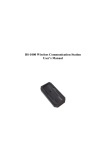
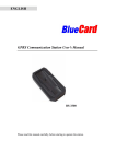
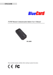
BS-4000 / BS-4000m Remote Communication Station
User’s Manual
The BS-4000 Remote Communication Station (Comm Station) system is able to collect
and remotely upload data from guard tour readers via land-line phone networks. There
are two versions of this product, and both are required for the system to work:
BP-4000 Client: Used at the remote locations to collect data from
guard tour readers and upload to the main office.
BP-4000m Server: Installed at the main office to receive connections
from BP-4000 Clients. It serves as a temporary storage place for
guard tour data, which can be later uploaded to the PC via a USB
connection.
Description of the BS-4000 hardware:
Status LED Lights
(in the descriptions below, “up” indicates the direction on the BS-4000 where the
status LED lights are located):
Red LED – Upper-Left
Flashing: communicating over the mobile phone network.
Constant on: the BS-4000 has data that needs to be uploaded.
Constant off: the BS-4000 does not have data that needs to be uploaded.
Green LED – Lower-Left
Flashing once per second: the BS-4000 is operating normally.
Red LED – Upper-Right
Constant on: the unit is connected with the remote unit via its modem
module.
Constant on: the unit is not connected with the remote unit via its modem
module.
Blue LED – Lower-Right
Flashing once per second: the BS-4000 is operating normally.
Flashing quickly: the BS-4000 is communicating with a guard tour reader.
Audio Signals
There are two types of audio signals: long beep and short beep.
Some of the audio signals below have multiple meanings depending on the situation.
Short Beep (once)
1
Guard tour reader found, but the reader does not contain data that needs to
be uploaded.
The local unit has connected successfully with the remote unit via the phone
line.
Short Beep (twice consecutively)
The phone line has not been connected properly.
The remote phone number is busy or is not being answered.
Guard tour reader found, and the reader contains data that needs to be
uploaded.
Short Beep (three times consecutively)
The BS-4000’s memory is full, please upload to the BS-4000m first.
Phone dialing has been disabled.
Long Beep (once)
Data transfer from the reader to the BS-4000 has been completed.
Long Beep (three times consecutively)
Data has been completely transferred via the phone line, and the line has
been disconnected.
Long Beep (once) + Short Beep (three times)
The BS-4000 not operable and needs to be initialized by the manufacturer.
Power Supply
The BS-4000 is able to use multiple types of power supplies:
USB connection to the computer.
9V AC adapter.
Car adapter.
The BS-4000 will turn on automatically after being connected to a power source.
The status LED lights will start flashing at a normal pace if the unit is operating
correctly.
2
Operating Instructions
1. Install the supplied setup software.
2. Setting up the dial-up number on the BS-4000 Client:
The number that the remote BS-4000 Client dials to connect and upload data to
the BS-4000m Server must be stored into the unit.
There are two ways to store the number into the BS-4000 Client:
Local Setup
Connect the BS-4000 Client to the PC using the USB cable provided.
Start the setup software and wait for it to find the unit.
Enter the number that you wish to store on this BS-4000 Client in the
bottom entry field, and press the button labeled “Store on Local Unit”
If the setup succeeds, the unit will emit one short beep, and the software
will display the words “Modem Dialing Number Setup Succeeded.”
If the setup initially fails because the BS-4000 Client is performing
other internal functions, please wait a few seconds and press the button
again.
Remote Setup
3
Connect the BS-4000m Server to the PC via the supplied USB cable.
Connect the BS-4000m Server to the local telephone line, and make
sure the BS-4000 Client at the remote location is also connected to its
telephone line.
Start the BS-4000 setup software.
Enter the phone number where the remote BS-4000 Client is connected
into the top entry field, and the number which you wish to store into the
BS-4000 Client into the second entry field.
Press the button labeled “Dial Number”. The BS-4000m Server will
attempt to dial and connect to the BS-4000 Client.
Once the software indicates that connection has been established, press
the button labeled “Store on Remote Unit” to save the number in the
bottom entry field into the remote BS-4000 Client.
If the setup succeeds, the BS-4000m will emit one short beep, and the
software will display the words “Modem Dialing Number Setup
Succeeded.”
3. Collecting data from guard tour readers:
Both the BS-4000 Client and the BS-4000m Server are able to collect data from
guard tour readers wirelessly. Compatible readers include models BP-2002S,
BP-2002-W, and BP-2002B-W.
Turn on the BS-4000 / BS-4000m.
Set the reader into the indentation on the BS-4000. For reader model BP2002S, please place its reading head between the status lights, and set its top
flush against the inside edge of the BS-4000.
If there is data that needs to be transferred from the reader to the BS-4000 /
BS-4000m, its blue LED light will start flashing rapidly, indicating that data
is being transferred. When the transfer process is complete, the BS-4000 /
BS-4000m will make one long beep, then one short beep periodically every
4
few seconds, indicating that the reader connected no longer has any data to
upload, and should be removed. If you have another reader that needs to
have its data transferred, please place it in the unit at this time.
If the BS-4000 / BS-4000m makes three short beeps, it means that its
memory is full, and will need to have it uploaded before being able to
collect any more data from readers.
4. Remote data upload
When the BS-4000 Client contains data that needs to be uploaded, if in 30
seconds it does not communicate with a reader or the PC, it will automatically
attempt to dial and connect to the BS-4000m Server in order to upload its data.
If for any reason, the BS-4000 Client fails to upload data upon the first try (for
example, if the BS-4000m server has not been turned on, or if the dial-up phone
number stored in it is wrong, etc.), the BS-4000 will try again once every 30
seconds for three times. If it fails all three times, the BS-4000 will stop for five
minutes before attempting to dial again.
Please go to the next step to upload data to the main software of PC.
5. Local data upload
Both the BS-4000 Client and the BS-4000m Server are capable of uploading
their store data to the PC directly.
Connect the unit to the PC using the provided USB cable.
Start the patrol management software, and select the appropriate
communication method.
Open the “connect” screen in the patrol management software, which will
automatically collect data from the BS-4000 / BS-4000m unit.
Troubleshooting
Not able to upload data from the guard tour readers.
Check to see if the reader is placed properly on the unit. The reading head of
the reader should be between the status lights of the unit, and its top should
be flush against the inside edge of the unit.
Please note that the BS-4000 / BS-4000m unit is not able to upload data
from guard tour readers when it is communicating with the PC.
The BS-4000 Client is not able to dial its stored phone number.
Please note that only the BS-4000 Client (not the BS-4000m Server) is able
to automatically dial to upload its stored data. Please make sure that the
proper version of the unit is being used.
If the upper-right red LED flashes once without emitting a beeping sound, it
indicates that no dial-up number has been stored in the unit. Please first
store the dial-up number using the BS-4000 setup program.
5
If the unit emits two short beeps, it indicates that either it did not detect a
working phone line, or that the dialed number is busy.
The patrol management software is not able to find the unit.
Please check the condition of the hardware installation by going into the
Windows Device Manager.
In all conditions, please first check to see if the BS-4000 / BS-4000m unit is operating
properly, by making sure that its LED lights are flashing at the appropriate intervals. If
not, please disconnect then reconnect its power source in order to reinitialize the unit.
6