1
4 Current AO with HART Module
Doc. Code: CE109416
PO2134
Revision: A
Product Description
The PO2134 module is part of Ponto Series and has 4 isolated analog outputs for current. This module is applied for control
and supervision of machines, automation processes and where it is required remote parameterization of transmitters through
an asset management tool that uses HART technology over PROFIBUS.
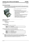
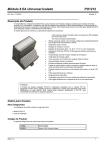
The picture shows the product installed on an analog I/O spring-clamp terminal base.
The module main features are:
•
Analog output module
•
Two current scales: 0-20 mA and 4-20 mA
•
HART protocol (4-20 mA)
•
Isolation for internal logic as for external power supply
•
Open current loop diagnosis
•
Local and remote diagnosis
•
Over-range for all modes
•
Hot swap with no interference on panel cabling
•
Remote parameterization via software
•
Remote parameterization of transmitters through asset
management tools
•
Field cabling connected to the terminal base, therefore
eliminating intermediary terminal blocks for field signals
•
Automatic addressing
ATTENTION:
This product is only compatible with PROFIBUS head PO5064 and PO5065.
Ordering Information
Included Items
The product packaging contains the following items:
•
•
PO2134 module
Installation guide
Product Code
The following code should be used to purchase the product:
Altus S. A.
Code
Description
PO2134
4 Current AO with HART Module
1
4 Current AO with HART Module
Doc. Code: CE109416
PO2134
Revision: A
Related Products
The following products must be purchased separately when necessary:
Code
Description
PO6001
Analog I/O spring-clamp terminal base
PO8510
10 Sheets with 14 labels of 16 tags for printer
PO8523
Spring Terminal Block Tool
Notes
PO8510: this product consists of A4 sheets with labels where the tags may be printed, in the case the user wishes so, using
MasterTool ProPonto Software - MT6000.
PO8523: this product is an isolated tool to connect the cables into the spring-clamp terminal bases PO6001 and PO6101.
Altus S. A.
2
4 Current AO with HART Module
Doc. Code: CE109416
PO2134
Revision: A
Product Features
General Features
PO2134
Module type
4 analog outputs
Output Type
Current
Data format
12 bits in 2 complement, aligned to the left
Converter resolution
12 bits monotonicity guaranteed, no missing codes
Terminal block configuration
1 terminal for current output (I)
1 terminal for each IO return (0 Vdc), interconnected (N)
1 terminal for shield cable (G)
Diagnostic indication
Two multifunctional LEDs with indication of module OK status,
open current loop and missing of parameterization
Configurable parameters
Output range per output point
Enabling of HART protocol
Hot swap
Yes
External power supply
19 to 30 Vdc including ripple
Maximum input current – 100 mA @ 24 Vdc
Initialization time
5 s (maximum)
Isolation
Outputs to logic circuits
1500 Vac up to 1 minute
Outputs to ground
1500 Vac up to 1 minute
Power supply to logic circuits
1500 Vac up to 1 minute
Power supply to outputs
1500 Vac up to 1 minute
Among outputs
No isolation
Bus power consumption
30 mA
Power consumption
2.4 W with all outputs on and current outputs short circuited to
the ground
1.2 W with all outputs off, range 4-20 mA
Dimensions
100 x 52 x 84 mm
Environment conditions
Consult general features of Ponto Series (CT109000)
Compatible bases
PO6001: Spring-clamp analog I/O terminal base
Notes
Power supply interruptions: power supply interruptions, during at least 10 ms may be supported, since the module is
operating in its nominal voltage of 24 Vdc or greater. Longer interruptions or in voltages lower than its nominal one may cause
module reset.
Altus S. A.
3
4 Current AO with HART Module
PO2134
Doc. Code: CE109416
Revision: A
Analog Outputs
PO2134 – Current Mode
± 0.1 % full range @ 25 oC
Precision
± 0.005% / oC full range
Load maximum impedance
600 Ω
Scanning time
Maximum 100 ms
Stabilization time
6 ms
Range
Counting
Resolution
0 to 20 mA
0 to 30000
5.7 µA
4 to 20 mA
0 to 30000
5.7 µA
4 to 20 mA with
HART
0 a 30000
5.7 µA
Ranges
Range slack
Minimum 4%
Open loop indication
Output voltage fault
Notes
Scanning time: maximum time between receiving the values from the bus until the output update (worst case– 4 channels).
The PO2134 module receives the 4 channels in 5 scanning polls from the Ponto bus (4 channels + 1 parameter). Please see
bus head manual for further details on the scanning time.
Stabilization time: time for the output to reach the programmed value with 1% precision.
Range slack: the range slack allows the module to reach voltages out of the range in order to compensate possible offset
errors from devices to be controlled. The range slack is specified for a 500 Ω load.
Open loop indication: activated when output voltage is higher than 13,5 V. It happens when the output cable breaks.
Resolution: indicates the minimum possible variation on the outputs, considering the number of bits of the DA converter and
the internal reference voltage source.
HART
PO2134
Operation mode
Monodrop
Allows secondary master
Yes
Compatibility With Other Products
The following table describes the main Altus products compatible with PO2134.
Compatible version
Altus S. A.
ProPonto MT6000
1.59 or upper
MasterTool MT8000
5.42 or upper
4
4 Current AO with HART Module
PO2134
Doc. Code: CE109416
Revision: A
Installation
ATTENTION:
This device is sensible to electrostatic discharge (ESD). Always touch a grounded metallic surface
before handling this device.
Electrical Installation
PO2134 module installation must be done on a PO6001 base.. The internal circuit is plotted in doted lines.
Altus S. A.
5
4 Current AO with HART Module
PO2134
Doc. Code: CE109416
Revision: A
Diagram Notes:
1- IO, I1, I2, I3 are the four current analog output.
2- All signals must be connected through shielded cables with the shield grounded to the G terminal block. Both ends should
not be grounded simultaneously.
3-Electrical installation is done by feeding the module base with a 24 Vdc power supply. This connection is done via terminals
marked by ( + ) and ( - ). This connection is mandatory, because it is the only way to supply power to the module.
4- The common point for the power supply (3) may be connected to the panel ground. This connection is not mandatory, but it
is recommended in order to reduce electric noise in automation systems.
5- The next module may be fed through the points ( + ) and ( - ) on this module base. The maximum number of module bases
that may be connected in this way is 10. No other device can be connected to these terminal strips.
Module Power Supply:
The PO2134 module uses a 24 Vdc regulated power supply – terminals ( + ) and ( - ).
Field Cabling:
•
•
•
When installing the module please follow procedures described below in order to avoid electromagnetic interference:
Avoid sharing the same conduit for high voltage or current cables (for instance motors power supply) and sensor cables.
Identify and eliminate other noise sources, such as faulty or unprotected contactors and sparks produced by the wearing down of
motors’ brushes.
Use shielded cables for carrying input signals and ground only one of the shielding ends.
The field elements should be connected to the base as shown on diagram. The terminal blocks identification have direct
correlation with the module IOs as follow:
Module I/O
0
1
2
3
Terminal block for current
output
I0
I1
I2
I3
Common terminal block
N0
N1
N2
N3
Grounding terminal block
G
G
G
G
ATTENTION:
Atmospheric discharges (lightnings) may cause damages to the modules although their
protections.
Additional protections should be used if module’s power comes from a power supply located
outside the cabinet where the module is installed, because this makes it vulnerable to this kind of
discharges.
If the field wiring of input points is susceptible to this kind of discharge, surge suppressors should
be used.
ATTENTION:
This is an analog module and its installation near radio-frequency emitter devices may interfere in
the precision of inputs. Avoid installing it near radio equipment, antennas and similar devices.
Field wiring should be shielded because radio-frequency coupling may occur in field signals.
The module has been tested with electromagnetic fields of intensities up to 10 V/m. In those
conditions, observed precision was at least 0.5% full range. This field intensity corresponds to the
maximum values considered by international standards to industrial environment. Stronger fields
can cause greater performance depreciation.
Tests with portable radio transmitters (walkie-talkies) near the module (1 m) caused no alteration
in nominal precision.
Altus S. A.
6
4 Current AO with HART Module
PO2134
Doc. Code: CE109416
Revision: A
Mechanical Assembly
The mechanical assembly is described in the Ponto Series Utilization Manual (MU209000). There are no special
requirements in mechanical assembly of this module.
Please adjust the module base mechanical code, when assembly this module on its base, to 34 (3 on switch A and 4 on
switch B).
Parameterization
The CPU or field network head defines via software the PO2134 module parameterization. The software which configures the
field bus master sets the parameterization. For further information, please consult Ponto Series Utilization Manual and
Manuals for the Interfaces and Field Network Heads. The parameterization is set through user-friendly menus. For reference
purposes, the binary codes are shown as follows.
Parameters Bytes
The module parameterization is defined by six bytes. The first two bytes set the general module aspects and
the remaining four bytes set the parameterization of each analog output.
The bytes are defined as the following.
Byte
Byte 0 - Module generics
7
6
5
4
0
0
0
0
Parameters
0
Module (General)
1
Module (General)
2
Channel 0
3
Channel 1
4
Channel 2
5
Channel 3
Description
3
2
1
0
0
1
1
0
Number of parameters bytes ( always 6 )
Always zero
Byte 1 - Module generics
Description
7
6
5
4
3
2
1
0
0
0
0
0
0
0
0
0
Always zero
The bytes 2 to 5 individually configure each analog channel.
Bytes 2 to 5
7
1
6
5
Description
4
3
0
0
0
0
0
0
0
0
2
1
0
0
0
0
Current: 4 to 20 mA
0
0
1
Current 0 to 20 mA
1
0
0
Current: 4 a 20 mA with HART
x
x
x
Disables output
Always zero
Notes
Disables output: if all channels are disabled, the outputs will be turned off and an configuration error diagnostic byte will be
returned on byte 0 (LED 17 blinks 1x).
Altus S. A.
7
4 Current AO with HART Module
PO2134
Doc. Code: CE109416
Revision: A
Example
Byte
Parameters
7
6
5
4
3
2
1
0
Value in
Hex
Description
0
Module
generics
0
0
0
0
0
1
1
0
06
Fixed value
1
Module
generics
0
0
0
0
0
0
0
0
00
Fixed value
2
Canal 0
0
0
0
0
0
0
0
0
00
Current 4 to 20 mA
3
Canal 1
0
0
0
0
0
1
0
0
04
Current 4 to 20 mA with
HART
4
Canal 2
0
0
0
0
0
0
0
1
01
Current 0 to 20 mA
5
Canal 3
0
0
0
0
0
1
0
0
04
Current 4 to 20 mA with
HART
Diagnosis
Diagnosis Bytes
The PO2134 module provides six bytes for operating diagnosis including status of each output.
The first two bytes indicate the general aspects related to the module operation.
Byte
Parameters
0
Module (General)
1
Module (General)
2
Channel 0
3
Channel 1
4
Channel 2
5
Channel 3
In the case when the module is part of a PROFIBUS remote, the diagnostic informations are provided to the CPU that
implements the PROFIBUS Master Network Interface only in case when there are any failures. In this case the error codes
are sent in decimal form.
Byte 0 – Module (General)
7
6
5
0
4
3
2
1
0
0
0
0
Description
-
Always zero
0
-
Functioning Normaly
1
31
0
Module not parameterized. Error with
parameterization
-
Always zero
0
-
Normal External voltage
1
02
0
External volage below 19 Vdc
-
Byte 1 – Module (General)
Altus S. A.
PROFIBUS message
code
7
6
5
4
3
2
1
0
0
0
0
0
0
0
0
0
Always zero
PROFIBUS Message Code
Description
-
Always zero
8
4 Current AO with HART Module
PO2134
Doc. Code: CE109416
Revision: A
Bytes 2 to 5, individually diagnoses
Bytes 2-5 – Channel Diagnosis
7
6
5
4
3
2
1
PROFIBUS Message Code
0
-
1
16
0
0
0
0
0
Description
0
Functioning Normaly
Wrong configuration for canal
-
Always zero
0
-
Normal current output
1
18
0
Open current output
-
Always zero
The diagnosis LED indicates the following situations:
LED DG
Meaning
On
Normal operation
Blinking 1X
Head is not accessing
module or logic fault at
module
Causes
Wrong module type for the position
Non declared module
Damaged module
Blinking 3X
External power supply
Missing external power supply
Blinking 4X
No continuity on the
current output
Open field cable
LED 17
Meaning
Causes
Off
No parameterization
Parameterization missing
On
Normal operation
Blinking 1X
Parameterization error
(the failure identification
is done through the
diagnosis byte)
Parameterization is not valid
All channels are disabled
Notes
LED 17: any diagnosis infiormation different from the ones listed above indicates that the module must be forwarded to Altus
Support service.
LED 17:the diagnosis priority is from the higher number of blinking times to the lower.
Altus S. A.
9
4 Current AO with HART Module
Doc. Code: CE109416
PO2134
Revision: A
Physical Dimensions
Dimensions in mm.
The electrical panel dimensions
should take into consideration the
module terminal base sizes.
Ponto Series Utilization Manual
IP20 (MU209000) must be
consulted for panel general
dimensioning.
Beside, there’s a PO2134 module
assembled on a PO6001 terminal
base on DIN TS35 rail.
Maintenance
Hot-swapping procedures are described in the Ponto Series Utilization Manual (MU209000).
All the module adjusts are set via software in Altus industrial area.
Manuals
For further technical details, configuration, installation and programming of Ponto Series products please consult following
documents:
Document Code
Description
CT109000
Ponto Series General Characteristics
MU209000
Ponto Series Utilization Manual - IP20
MU299040
User Manual MT6000 – MasterTool ProPonto
MU209503
User Manual PO5064 and PO5065 - PROFIBUS Head
MU299604
User Manual MasterTool MT8000
MU203026
User Manual ProfiTool - AL-3865
Also consult the user manuals for the field network heads and compatible CPUs.
Altus S. A.
10