1
Technical Report
UCAM-CL-TR-853
ISSN 1476-2986
Number 853
Computer Laboratory
Bluespec Extensible
RISC Implementation:
BERI Software reference
Robert N.M. Watson, David Chisnall,
Brooks Davis, Wojciech Koszek,
Simon W. Moore, Steven J. Murdoch,
Peter G. Neumann, Jonathan Woodruff
April 2014
15 JJ Thomson Avenue
Cambridge CB3 0FD
United Kingdom
phone +44 1223 763500
http://www.cl.cam.ac.uk/
c 2014 Robert N.M. Watson, David Chisnall, Brooks Davis,
Wojciech Koszek, Simon W. Moore, Steven J. Murdoch,
Peter G. Neumann, Jonathan Woodruff
Sponsored by the Defense Advanced Research Projects
Agency (DARPA) and the Air Force Research Laboratory
(AFRL), under contract FA8750-10-C-0237 (“CTSRD”) as
part of the DARPA CRASH research program. The views,
opinions, and/or findings contained in this report are those of
the authors and should not be interpreted as representing the
official views or policies, either expressed or implied, of the
Defense Advanced Research Projects Agency or the
Department of Defense.
Technical reports published by the University of Cambridge
Computer Laboratory are freely available via the Internet:
http://www.cl.cam.ac.uk/techreports/
ISSN 1476-2986
Abstract
The BERI Software Reference documents how to build and use the FreeBSD operating system
on the Bluespec Extensible RISC Implementation (BERI) developed by SRI International and
the University of Cambridge. The reference is targeted at hardware and software programmers
who will work with BERI or BERI-derived systems.
3
Acknowledgments
The authors of this report thank other current and past members of the CTSRD team, and our
past and current research collaborators at SRI and Cambridge:
Ross J. Anderson
Jonathan Anderson
Khilan Gudka
Jong Hun Han
Asif Khan
Myron King
Anil Madhavapeddy Ilias Marinos
Andrew Moore
Will Morland
Robert Norton
Philip Paeps
John Rushby
Hassen Saidi
Stacey Son
Richard Uhler
Gregory Chadwick
Alex Horsman
Ben Laurie
A. Theodore Markettos
Alan Mujumdar
Michael Roe
Hans Petter Selasky
Philip Withnall
Nirav Dave
Alexandre Joannou
Patrick Lincoln
Ed Maste
Prashanth Mundkur
Colin Rothwell
Muhammad Shahbaz
Bjoern Zeeb
The CTSRD team wishes thank its external oversight group for significant support and contributions:
Lee Badger
Simon Cooper
Rance DeLong Jeremy Epstein
Virgil Gligor
Li Gong
Mike Gordon
Steven Hand
Andrew Herbert
Warren A. Hunt Jr. Doug Maughan Greg Morrisett
Brian Randell
Kenneth F. Shotting Joe Stoy
Tom Van Vleck
Samuel M. Weber
Finally, we are grateful to Howie Shrobe, MIT professor and past DARPA CRASH program
manager, who has offered both technical insight and support throughout this work. We are also
grateful to Robert Laddaga, who has succeeded Howie in overseeing the CRASH program.
4
Contents
1
2
3
Introduction
1.1 Bluespec Extensible RISC Implementation (BERI)
1.2 FreeBSD . . . . . . . . . . . . . . . . . . . . . .
1.3 Getting BERI . . . . . . . . . . . . . . . . . . . .
1.4 Licensing . . . . . . . . . . . . . . . . . . . . . .
1.5 Version History . . . . . . . . . . . . . . . . . . .
1.6 Document Structure . . . . . . . . . . . . . . . . .
Building FreeBSD/BERI
2.1 Obtaining FreeBSD/BERI Source Code . . .
2.2 About FreeBSD/BERI . . . . . . . . . . . .
2.3 Building FreeBSD/BERI . . . . . . . . . . .
2.3.1 Configuring the Build Environment .
2.3.2 Cross-Building World . . . . . . . .
2.3.3 Cross-Building a Kernel . . . . . . .
2.4 Cross-Installing FreeBSD . . . . . . . . . . .
2.4.1 Cross-Installing World . . . . . . . .
2.4.2 Cross-Installing Kernels . . . . . . .
2.4.3 Preparing a Memory Root Filesystem
2.5 Preparing a FreeBSD SD Card Image . . . .
2.6 Automated Builds . . . . . . . . . . . . . . .
.
.
.
.
.
.
.
.
.
.
.
.
.
.
.
.
.
.
.
.
.
.
.
.
.
.
.
.
.
.
.
.
.
.
.
.
.
.
.
.
.
.
.
.
.
.
.
.
.
.
.
.
.
.
.
.
.
.
.
.
.
.
.
.
.
.
.
.
.
.
.
.
.
.
.
.
.
.
.
.
.
.
.
.
.
.
.
.
.
.
.
.
.
.
.
.
.
.
.
.
.
.
.
.
.
.
.
.
.
.
.
.
.
.
.
.
.
.
.
.
.
.
.
.
.
.
.
.
.
.
.
.
.
.
.
.
.
.
.
.
.
.
.
.
.
.
.
.
.
.
.
.
.
.
.
.
.
.
.
.
.
.
.
.
.
.
.
.
.
.
.
.
.
.
.
.
.
.
.
.
.
.
.
.
.
.
.
.
.
.
.
.
.
.
.
.
.
.
Using FreeBSD/BERI
3.1 Getting Started with FreeBSD . . . . . . . . . . . . . . . . . . . .
3.1.1 Obtaining FreeBSD/BERI . . . . . . . . . . . . . . . . . .
3.1.2 Building berictl . . . . . . . . . . . . . . . . . . . . . . . .
3.1.3 Writing Out the SD Card Disk Image (FPGA only) . . . . .
3.1.4 Setting Up the DE4 Development Environment (FPGA only)
3.1.5 JTAG (FPGA only) . . . . . . . . . . . . . . . . . . . . . .
3.2 Booting FreeBSD in Simulation . . . . . . . . . . . . . . . . . . .
3.2.1 Using the berictl debugger . . . . . . . . . . . . . . . . . .
3.3 Programming the DE4 FPGA . . . . . . . . . . . . . . . . . . . . .
3.3.1 Writing an FPGA Bitfile to DE4 Flash from FreeBSD . . .
3.3.2 Start a Console . . . . . . . . . . . . . . . . . . . . . . . .
3.4 Models for Booting a FreeBSD/BERI Kernel . . . . . . . . . . . .
3.4.1 Load a Kernel into DRAM over JTAG . . . . . . . . . . . .
5
.
.
.
.
.
.
.
.
.
.
.
.
.
.
.
.
.
.
.
.
.
.
.
.
.
.
.
.
.
.
.
.
.
.
.
.
.
.
.
.
.
.
.
.
.
.
.
.
.
.
.
.
.
.
.
.
.
.
.
.
.
.
.
.
.
.
.
.
.
.
.
.
.
.
.
.
.
.
.
.
.
.
.
.
.
.
.
.
.
.
.
.
.
.
.
.
.
.
.
.
.
.
.
.
.
.
.
.
.
.
.
.
.
.
.
.
.
.
.
.
.
.
.
.
.
.
.
.
.
.
.
.
.
.
.
.
.
.
.
.
.
.
.
.
.
.
.
.
.
.
.
.
.
.
.
.
.
.
.
.
.
7
7
7
8
8
8
9
.
.
.
.
.
.
.
.
.
.
.
.
10
10
10
11
11
13
13
13
14
14
14
15
16
.
.
.
.
.
.
.
.
.
.
.
.
.
17
17
18
18
18
20
20
20
21
21
23
23
23
24
.
.
.
.
.
.
.
.
.
.
.
.
.
.
.
.
.
.
.
.
.
.
.
.
.
.
.
.
.
.
.
.
.
.
.
.
.
.
.
.
.
.
.
.
.
.
.
.
.
.
24
25
25
25
26
FreeBSD/BERI Device-Driver Reference
4.1 Device Drivers for Altera IP Cores . . . . . . . . . . . . . . .
4.1.1 Altera JTAG UART . . . . . . . . . . . . . . . . . . .
4.1.2 Generic Avalon Device Driver . . . . . . . . . . . . .
4.1.3 Altera University Program SD Card IP Core . . . . . .
4.1.4 Altera Triple-Speed Ethernet . . . . . . . . . . . . . .
4.2 Device Drivers for Terasic Components . . . . . . . . . . . .
4.2.1 Terasic DE4 8-Element LED . . . . . . . . . . . . . .
4.2.2 Common Flash Memory Interface . . . . . . . . . . .
4.2.3 Flash Partitioning . . . . . . . . . . . . . . . . . . . .
4.2.4 Cambridge/Terasic Multi-Touch LCD Display (MTL)
.
.
.
.
.
.
.
.
.
.
.
.
.
.
.
.
.
.
.
.
.
.
.
.
.
.
.
.
.
.
.
.
.
.
.
.
.
.
.
.
.
.
.
.
.
.
.
.
.
.
.
.
.
.
.
.
.
.
.
.
.
.
.
.
.
.
.
.
.
.
.
.
.
.
.
.
.
.
.
.
.
.
.
.
.
.
.
.
.
.
27
27
27
28
29
30
31
31
32
33
33
3.5
3.6
4
3.4.2 Load a Kernel into Flash from FreeBSD . . . . . .
Start Kernel Execution . . . . . . . . . . . . . . . . . . .
Post-Boot Issues . . . . . . . . . . . . . . . . . . . . . . .
3.6.1 Increasing the Size of an SD Card Root Filesystem
3.6.2 Setting a MAC Address . . . . . . . . . . . . . .
6
.
.
.
.
.
Chapter 1
Introduction
This is the Software Reference for the Bluespec Extensible RISC Implementation (BERI) prototype. The Software Reference describes the software development environment on the BERI
processor – especially, as relates using the FreeBSD operating system on FPGA-synthesized
BERI systems. The reference is intended to address the needs of hardware and software developers who are prototyping new hardware features, bringing up operating systems, language
runtimes, and compilers on BERI, rather than literal end users. It complements the BERI
Hardware Reference, which describes the BERI physical platform, the CHERI Architecture
Document, which describes our CHERI ISA extensions, and the CHERI User’s Guide, which
describes our software extensions for CHERI.
1.1
Bluespec Extensible RISC Implementation (BERI)
The Bluespec Extensible RISC Implementation (BERI) is a platform for performing research
into the hardware-software interface that has been developed as part of the CTSRD project
at SRI International and the University of Cambridge. It consists of a 64-bit FPGA soft-core
processor implemented in Bluespec System Verilog and a complete software stack based on
FreeBSD, Clang/LLVM, and a range of popular open-source software products. BERI implements a roughly 1994-vintage version of the 64-bit MIPS ISA with FPU and system coprocessor sufficient to support a full operating-system implementation. It also implements research extensions such as the CHERI ISA, which supports fine-grained memory protection and
scalable compartmentalization within conventional address spaces. Wherever possible, BERI
makes use of BSD- and Apache-licensed software to maximize opportunities for technology
transition.
1.2
FreeBSD
FreeBSD is an open-source UNIX operating system originating from the Berkeley Software
Distribution in the 1980s. Released under the liberal BSD open-source license, FreeBSD is
widely used in service provider environments (e.g., Yahoo!, Verio, ISC, Netflix) and as a foundation for commercial appliance and embedded products (e.g., NetApp, Juniper, Cisco, EMC,
Apple). We have adapted FreeBSD to run on BERI, which includes a platform support package and a set of device drivers for common Altera and Terasic peripherals. As part of the BERI
7
effort, we have invested significant effort in improving upstream components such as LLVM
and LLDB to work well with the 64-bit MIPS ISA.
FreeBSD can be cross-compiled from 32-bit and 64-bit x86 workstations and servers running FreeBSD (or from a VM running FreeBSD). We have also adapted the FreeBSD thirdparty package build system (‘ports’) to support cross-compilation, making tens of thousands of
open-source applications (e.g., Apache) available on BERI. FreeBSD is of particular interest
to teaching and research in the hardware-software interface due to tight integration with the
Clang/LLVM compiler suite.
1.3
Getting BERI
We distribute the BERI prototype and software stack as open source via the BERI website:
http://www.beri-cpu.org/
1.4
Licensing
The BERI hardware design, simulated peripherals, and software tools are available under the BERI
Hardware-Software License, a lightly modified version of the Apache Software License that takes into
account hardware requirements.
We have released our extensions to the FreeBSD operating system to support BERI under a BSD
license; initial support for BERI was included in FreeBSD 10.0, but further features will appear in
FreeBSD 10.1. We have also released versions of FreeBSD and Clang/LLVM that support the CHERI
ISA under a BSD license; these are distributed via GitHub.
We welcome contributions to the BERI project; however, we are only able to accept non-trivial
changes when an individual or corporate contribution agreement has been signed. The BERI hardwaresoftware license and contribution agreement may be found at:
http://www.beri-open-systems.org/
1.5
Version History
Portions of this document were previously made available as part of the CHERI User’s Guide.
1.0 An initial version of the CHERI User’s Guide documented the implementation status of the CHERI
prototype, including the CHERI ISA and processor implementation, as well as user information
on how to build, simulate, debug, test, and synthesize the prototype.
1.1 Minor refinements were made to the text and presentation of the document, with incremental updates
to its descriptions of the SRI/Cambridge development and testing environments.
1.2 This version of the CHERI User’s Guide followed an initial demonstration of CHERI synthesized
for the Terasic tPad FPGA platform. The Guide contained significant updates on the usability
of CHERI features, the build process, and debugging features such as CHERI’s debug unit. A
chapter was added on Deimos, a demonstration microkernel for the CHERI architecture.
1.3 The document was restructured into hardware prototype and software reference material. Information on the status of MIPS ISA implementation was updated and expanded, especially with
8
respect to the MMU. Build dependencies were updated, as was information on the CHERI simulation environment. The distinction between BERI and CHERI was discussed in detail. The
Altera development environment was described in its own chapter. A new chapter was added that
detailed bus and device configuration and use of the Terasic tPad and DE4 boards, including the
Terasic/Cambridge MTL touch screen display. New chapters were added on building and using
CheriBSD, as well as a chapter on FreeBSD device drivers on BERI/CHERI. A new chapter was
added on cross-building and using the CHERI-modified Clang/LLVM suite, including C-language
extensions for capabilities.
1.4 This version introduced improved Altera build and Bluespec simulation instructions. A number
of additional C-language extensions that can be mapped into capability protections were introduced. FreeBSD build instructions were updated for changes to the FreeBSD cross-build system.
Information on the CHERI2 prototype was added.
1.5 In this version of the CHERI User’s Guide, several chapters describe the CHERI hardware prototype
have been moved into a separate document, the CHERI Platform Reference Manual, leaving the
User’s Guide focused on software-facing activities.
1.6 This version updated the CHERI User’s Guide for changes in the CheriBSD build including support
for the CFI driver, incorporation of Subversion into the FreeBSD base tree, and non-root cross
builds. It also added information on the quartus_pgm command, and made a number of minor
clarifications and corrections throughout the document.
1.7 In this revision, the BERI Software Reference became an independent document from the CHERI
User’s Guide. This version was updated for the complete merge of FreeBSD/BERI to the FreeBSD
Subversion repository, and migration of CheriBSD to GitHub. It reflects the change from cherictl
to berictl and a number of enhancements to berictl that avoid the need to manually invoke
Altera’s underlying tools for FPGA programming or console access. The isf driver has been
replaced with use of the stock FreeBSD cfi driver. We no longer recommend explicitly building
the cross-toolchain; instead, rely on world.
1.8 - UCAM-CL-TR-853 This version of the BERI Software Reference was made available as a University of Cambridge Technical Report. Information was updated to reflect open sourcing of
BERI/CHERI and its software stack.
1.6
Document Structure
This document is an introduction and user manual for Version 1 of the Bluespec Extensible RISC Implementation (BERI) CPU prototype:
Chapter 2 describes how to build the FreeBSD/BERI port from source. You do not need to do this if
using prebuilt kernels.
Chapter 3 describes how to use FreeBSD/BERI.
Chapter 4 provides additional reference material for device driver configuration and use under FreeBSD/BERI.
9
Chapter 2
Building FreeBSD/BERI
FreeBSD/BERI is an adaptation of the open-source FreeBSD operating system to run on the Bluespec Extensible RISC Implementation (BERI). This support has been ‘upstreamed’ to the mainstream
FreeBSD distribution, and appears from version FreeBSD 10.0 onwards. As we are actively continuing development of FreeBSD/BERI, we have extended it to support evolving features in BERI itself,
including device drivers for new hardware peripherals, and kernel support for new CPU features. FreeBSD/BERI can be cross-compiled from 32-bit or 64-bit FreeBSD/x86 running FreeBSD 10.0. CheriBSD,
a set of extensions to FreeBSD/BERI to support the CHERI capability coprocessor, are described in a
separate document, the CHERI User’s Guide.
2.1
Obtaining FreeBSD/BERI Source Code
FreeBSD/BERI has been merged to the FreeBSD source tree as released in FreeBSD 10.0. However,
due to post-FreeBSD 10.0 enhancements, we recommend using FreeBSD 10-STABLE, which can be
tracked in the following Subversion branch:
http://svn.freebsd.org/base/stable/10
For closer (and likely faster) access to the repository see the list of mirrors found at:
http://www.freebsd.org/doc/en_US.ISO8859-1/books/handbook/svn-mirrors.
html
With some caution, the FreeBSD development head (11-CURRENT) might also be used in order to get
the very latest BERI features. (For example, at the time of writing, BERI boot-loader support is only
present in that branch.) However, as 11-CURRENT includes many other experimental in-development
OS features, this is not recommended unless you are able to closely track FreeBSD development mailing
lists to be aware of evolving sources of instability:
http://svn.freebsd.org/base/head
2.2
About FreeBSD/BERI
The FreeBSD/BERI port is adapted from the FreeBSD/MALTA 64-bit MIPS port, which offers the
closest match in terms of ISA. BERI- related kernel files may be found in directories listed in Table 2.1.
Wherever possible, FreeBSD/BERI reuses generic MIPS platform code, and is successful in almost all
cases. BERI uses flattened device tree (FDT); currently, DTS files describing BERI hardware are stored
10
Filename
Description
sys/mips/beri/
sys/boot/fdt/dts/mips
BERI-specific processor/platform code.
Home of BERI flattened device tree (FDT) description files.
sys/dev/altera/atse
sys/dev/altera/avgen
Altera Triple-Speed Ethernet MAC.
Avalon “generic” driver to export I/O address ranges
to userspace.
Altera JTAG UART device driver.
Altera University Program SD Card IP core device
driver.
Terasic DE4 LED array device driver.
Terasic Multitouch LCD device driver.
sys/dev/altera/jtag_uart
sys/dev/altera/sdcard
sys/dev/terasic/de4led
sys/dev/terasic/mtl
Table 2.1: FreeBSD/BERI directories in src/sys/
in the FreeBSD source tree, but we hope to embed them in ROMs in BERI bitfiles in the future. Table 2.2
lists BERI-specific files in the common MIPS configuration directory.
2.3
Building FreeBSD/BERI
The following sections describe how to build a FreeBSD/BERI system. Examples assume the Cambridge
zenith development environment, a FreeBSD 10.0 x86/64 server. With appropriate pathname and
username substitutions, they should work on other FreeBSD 10 build hosts. The FreeBSD userspace
build will automatically build suitable cross-compilers and tools. Once userspace has been built, it must
be installed to a suitable directory tree from which disk images can be created. If you wish to build a
kernel that includes a memory root filesystem, userspace must be built, installed to a temporary location,
and a memory file system image created, before the kernel can be built.
Where appropriate, cheribsd may be substituted for freebsd, and kernel configuration file
names changed, to build CheriBSD instead of FreeBSD/BERI. Please consult the CHERI User’s Guide
for instructions on checking out CheriBSD source code.
Note well: The details of the build process are likely to change over time as we merge changes from
the upstream FreeBSD tree due to the rapid evolution of MIPS support. Users should take care to ensure
that they are using a BERI Software reference that is contemporary with their source tree.
2.3.1
Configuring the Build Environment
By default, the FreeBSD build system will use /usr/obj as its scratch area. Instead, create and
configure your own per-user scratch space:
mkdir -p ${HOME}/obj
export MAKEOBJDIRPREFIX=${HOME}/obj
You may wish to modify your .cshrc or .bashrc to automatically configure the MAKEOBJDIRPREFIX
variable every time you log in.
11
Filename
Description
BERI_DE4.hints
BERI_SIM.hints
BERI_TPAD.hints
Terasic DE4 hardware configuration hints
Bluespec simulation hardware configuration hints
Terasic tPad hardware configuration hints
BERI_TEMPLATE
FreeBSD/BERI template configuration entries,
included by more specific kernel configuration files
FreeBSD/BERI template configuration entries
for DE4 configurations, included by DE4 kernel
configuration files
FreeBSD/BERI kernel configuration to use a memory root filesystem on the Terasic DE4
FreeBSD/BERI kernel configuration to use an SD
Card root filesystem on the Terasic DE4
FreeBSD/BERI template configuration entries
for DE4 configurations, included by DE4 kernel
configuration files
FreeBSD/BERI kernel configuration to use a memory root filesystem while in simulation
FreeBSD/BERI kernel configuration to use a simulated SD Card root filesystem
BERI_DE4_BASE
BERI_DE4_MDROOT
BERI_DE4_SDROOT
BERI_SIM_BASE
BERI_SIM_MDROOT
BERI_SIM_SDROOT
Table 2.2: FreeBSD/BERI files in src/sys/mips/conf; note that hints files have been
deprecated in favor of FDT DTS files for board configuration.
12
2.3.2
Cross-Building World
In FreeBSD parlance, “world” refers to all elements of the base operating system other than the kernel –
i.e., userspace. This includes system libraries, the toolchain (including the compiler), userland utilities,
daemons, and generated configuration files. It excludes third-party software such as Apache, X11, and
Chrome. Cross-build a big-endian, 64-bit MIPS world with the following commands:
cd ${HOME}/freebsd
make -j 16 TARGET=mips TARGET_ARCH=mips64 DEBUG_FLAGS=-g \
-DMALLOC_PRODUCTION buildworld
Note: the DEBUG_FLAGS=-g requests generation of debugging symbols for all userland components.
The atsectl utility allows the MAC address to be set in flash when FreeBSD/BERI is run on a
Terasic DE4 FPGA board. It is part of the FreeBSD source tree, but not built by default as it is only
useful on that platform and often run only once per board. It is stored in the tools/tools/atsectl
directory and can be built and installed with world by adding the following to the make command
lines:
LOCAL_DIRS="tools/tools/atsectl"
2.3.3
Cross-Building a Kernel
FreeBSD kernels are compiled in the context of a configuration file. For BERI, we have provided several
reference configuration files as described earlier in this chapter. In this section we describe only how to
build a kernel without a memory root filesystem. Information on memory root filesystems may be found
in Section 2.4.3. The following commands cross-build a BERI kernel:
cd ${HOME}/freebsd
make -j 16 TARGET=mips TARGET_ARCH=mips64 buildkernel \
KERNCONF=BERI_DE4_SDROOT
Notice that the kernel configuration used here is BERI_DE4_SDROOT; replace this with other configuration file names as required.
BERI uses FDT to describe most aspects of hardware configuration (including bus topology and peripheral attachments). The only significant exception is physical memory configuration, which is passed
directly to the kernel by the boot loader; we anticipate that physical memory will also be configured using FDT in the future. For the time being, DTS files describing hardware are embedded in the FreeBSD
source tree in a manner similar to hints files used in earlier iterations of BERI. In the future, these
will be embedded in hardware and a pointer to the configuration will be passed to the FreeBSD kernel
on boot by the loader.
2.4
Cross-Installing FreeBSD
The install phase of the FreeBSD build process takes generated userspace and kernel binaries from
the MAKEOBJDIRPREFIX and installs them into a directory tree that can then be converted into a
filesystem image. Most make targets in this phase make use of the DESTDIR variable to determine
where files should be installed to. Typically, DESTDIR will be set to a dedicated scratch directory such
as ${HOME}/freebsd-root. We advise you to remove the directory between runs to ensure that no
artifacts slip from one instance into a later one:
rm -Rf ${HOME}/freebsd-root
mkdir -p ${HOME}/freebsd-root
13
2.4.1
Cross-Installing World
This phase consists of two steps: installworld, which installs libraries, daemons, command line
utilities, and so on; and distribution, which creates additional files and directories used in the
installed configuration, such as /etc and /var. The following commands cross-install to
${HOME}/freebsd-root
cd ${HOME}/freebsd
make DESTDIR=${HOME}/freebsd-root \
TARGET=mips TARGET_ARCH=mips64 -DDB_FROM_SRC -DNO_ROOT \
installworld distribution
To install the software in the tools/tools/atsectl directory, the following should be added to
the make command line:
LOCAL_DIRS="tools/tools/atsectl"
2.4.2
Cross-Installing Kernels
As with world, kernels can be installed to a target directory tree along with any associated modules. The
following commands install the BERI_DE4_SDROOT kernel into ${HOME}/freebsd-root:
cd ${HOME}/freebsd
make DESTDIR=${HOME}/freebsd-root \
TARGET=mips TARGET_ARCH=mips64 -DDB_FROM_SRC -DNO_ROOT \
KERNCONF=BERI_DE4_SDROOT installkernel
2.4.3
Preparing a Memory Root Filesystem
To build the BERI_DE4_MDROOT kernel, a memory file system image must first be made available.
A demonstration script, makeroot.sh, is available via the CTSRD Subversion repository or CHERI
distribution; most users will wish to customize the script arguments based on their specific environment.
The following command generates a 26-megabyte root filesystem image in ${HOME}/mdroot.img,
and requires that previous steps to install world have been completed and assumes access to a checkout
of the CTSRD repository in ${HOME}/ctsrd:
cd ${HOME}/ctsrd/cheribsd/trunk/bsdtools
sh makeroot.sh -B big -e extras/sdroot.mtree -s 26112k -f net.files \
${HOME}/mdroot.img ${HOME}/freebsd-root
You must also customize BERI_DE4_MDROOT in order to notify it of the memory location of the root
filesystem image. Modify the following section of its configuration file to reflect the size of the generated
filesystem:
options
options
options
MD_ROOT # MD is a potential root device
MD_ROOT_SIZE="26112"
ROOTDEVNAME=\"ufs:md0\"
You may optionally add the following line to include the filesystem when the kernel is built:
makeoptions MFS_IMAGE=${HOME}/mdroot.img
14
Alternatively, you can embed the image by running the following command on a kernel that was previouly built without the MFS_IMAGE line:
sh ${HOME}/freebsd/sys/tools/embed_mfs.sh kernel.debug \
${HOME}/mdroot.img
Once the root filesystem image is generated, and the kernel configuration file updated, you can build the
kernel:
cd ${HOME}/freebsd
make -j 16 TARGET=mips TARGET_ARCH=mips64 buildkernel \
KERNCONF=BERI_DE4_MDROOT
The resulting kernel can be found in your MAKEOBJDIRPREFIX tree. If you did not add the MFS_IMAGE
variable you must then run embed_mfs.sh.
2.5
Preparing a FreeBSD SD Card Image
Build and install world and distribution as described in earlier sections. Then build and install
a kernel using the configuration file BERI_DE4_SDROOT. Apply a few tweaks to configuration files,
then use the makefs command to generate a UFS image file:
sudo su echo "/dev/altera_sdcard0 / ufs rw 1 1" > \
${HOME}/freebsd-root/etc/fstab
RCCONF=${HOME}/freebsd-root/etc/rc.conf
cat > ${RCCONF} <<EOF
hostname="beri1"
sendmail_submit_enable="NO"
sendmail_outbound_enable="NO"
cron_enable="NO"
tmpmfs="YES"
EOF
METALOG=${HOME}/freebsd-root/METALOG
echo "./etc/fstab type=file uname=root gname=wheel mode=0644" >> \
${METALOG}
echo "./etc/rc.conf type=file uname=root gname=wheel mode=0644" >> \
${METALOG}
cd ${HOME}/freebsd-root && makefs -B big -s 1886m -D \
-N ${HOME}/freebsd-root/etc \
${HOME}/beribsd-sdcard.img METALOG
This command creates a big-endian filesystem of size 1, 977, 614, 336 bytes – the size of the Terasic
2 GB SD Cards shipped with the tPad and DE4 boards. The resulting beribsd-rootfs.img can
then be installed on an SD Card using dd as described in later sections.
If a smaller filesystem is desired (e.g., one that can be more quickly prepared and written to the
SD card), then size 1, 977, 614, 336 bytes (2GiB) can be replaced by 512m or the -s argument can be
omitted entirely to create a minimally sized root image.
15
2.6
Automated Builds
The files described in Chapter 3 can be built with the help of the Makefile in:
cheribsd/trunk/bsdtools/
The template config file in Makefile.conf.template can be copied to Makefile.conf
and customized to your environment. The worlds target runs the buildworld, installworld,
and distribution for each source tree. The images target builds filesystem images from the
installed root directories. The kernels target builds kernels, including MDROOT kernels with images
build by images target. The sdcard target builds an an image suitable for writing to the SD Card.
The flash target builds flash preparation images for each kernel. Finally, the dated target makes
dated stamped files of each compressed kernel and image. All the above steps except for running the
dated target may be accomplished with the default all target.
All these targets support the make flag -j. We strongly encourage passing an appropriate value to
-j. In addition to standard FreeBSD tools, the Makefile requires installation of the archives/pxz
port or package.
16
Chapter 3
Using FreeBSD/BERI
This chapter describes the installation and use of FreeBSD/BERI on the Terasic DE4 FPGA board. We
have structured our modifications to FreeBSD into two development branches:
• FreeBSD/BERI is a version of FreeBSD that can run on the BERI hardware-software research
platform as a general-purpose OS.
• CheriBSD is a version of FreeBSD/BERI that has been enhanced to make use of CHERI’s experimental capability coprocessor features.
At the time of writing, FreeBSD has been modified to support a number of BERI features, such as
peripheral devices present on the Terasic DE4 board. CheriBSD extends FreeBSD/BERI to initialize
and maintain CHERI coprocessor registers; more information on CheriBSD can be found in the CHERI
User’s Guide.
3.1
Getting Started with FreeBSD
To get started with FreeBSD/BERI, you need the following:
• Ubuntu development PC or VM (version 14.04 recommended)
• Pre-built or custom-compiled FreeBSD kernel
• Pre-built or custom-compiled FreeBSD root filesystem image
For FPGA targets you also need:
• Terasic DE4 board with supplied 1GB DRAM
• Altera Quartus tools (version 13.1 recommended)
• 2GB SD card1
• BERI bitfile targeted for the Terasic DE4
1
Note: Altera’s University Program SD Card IP Core does not support SD cards larger than 2GB.
17
Synchronized versions of BERI FPGA bitfiles and FreeBSD must be used together: as the prototype
evolves, hardware-software interfaces change, as do board configurations; mismatched combinations
will almost certainly function incorrectly. The installed Quartus toolchain should also match the one
used to generate the bitfile being programmed, in order to avoid documented incompatibility.
The remainder of the chapter describes how to obtain FreeBSD kernels and root file-system images,
boot FreeBSD in simulation, write the FreeBSD root file-system image onto the SD card, program the
Terasic DE4 FPGA with a BERI bitfile, set up the JTAG debugging tunnel so that the berictl tool
can manipulate BERI via its debug unit, connect to the BERI console using nios2-terminal over
JTAG, and optionally re-flash the DE4’s on-board CFI flash with a bitfile and kernel to avoid the need to
program them via JTAG on every boot.
3.1.1
Obtaining FreeBSD/BERI
Pre-generated images of FreeBSD/BERI and CheriBSD may be downloaded from the BERI website:
http://www.beri-cpu.org/
Additionally, FreeBSD/BERI and CheriBSD may be built from source code using the instructions found in Chapter 2. Finally, pre-compiled snapshots of key files and images may be found in
/usr/groups/ctsrd/cheri in the Cambridge environment. Each file is named based on the date
is was generated, consisting of YYYYMMDDv where v is an optional letter indicating further builds that
occurred on the same day.
Table 3.1 describes file types that may be found in on the early adopters page and in the above
mentioned directory; all bitfiles and kernels are compressed using bzip2 and all filesystem images are
compressed with xz. Filesystems images must be decompressed before they can be used. Files passed
to berictl may be uncompressed; alternatively, the -z flag may be used to decompress them on the
fly.
3.1.2
Building berictl
berictl is a front-end to a variety of development and debugging features associated with the BERI
processor, both in simulation and when synthesized to FPGA. berictl will generally communicate
with the BERI debug unit over JTAG or a socket.
For building you will require the libbz2 library (libbz2-dev package in Ubuntu 14.04). To
compile:
cd cherilibs/trunk/tools/debug
make
3.1.3
Writing Out the SD Card Disk Image (FPGA only)
To use FreeBSD/BERI on FPGA with an SD Card root filesystem, write out the file system image on
an existing Mac, FreeBSD, Linux, or Windows workstation. The following command is typical for a
UNIX system; ensure that the disk device name here is actually your SD Card and not another drive!
$ dd if=arcina-beribsd-sdcard.img of=/dev/disk1 bs=512
On Mac OS X, diskutil list may be used to list possible devices to write to. You may need
to use diskutil unmountDisk (or DiskUtility.app) to first unmount an auto-mounted FAT
filesystem if one existed when the card was inserted. Note that SD cards should not be initialized with
FAT or other filesystems, and such filesystems may need to be unmounted before the first image is
18
Filename
Description
DE4 kernel with built-in
memory root filesystem with
basic network tools
beribsd-de4-kernel-singleuser-mdroot DE4 kernel with built-in
memory root filesystem that
drops to single user mode
with limited tools
beribsd-de4-kernel-sdroot
DE4 kernel using an SD
Card as a root filesystem
beribsd-sim-kernel-mdroot
Simulation kernel with
build-in memory root filesystem
beribsd-sim-kernel-sdroot
Simulation kernel a simulated SD Card as a root
filesystem
beribsd-flashboot
FreeBSD boot2 compiled
for direct execution and self
relocation from flash. Not
yet used
beribsd-jtagboot
FreeBSD boot2 compiled
for execution at 0x100000,
may be installed in flash in
place of a kernel
beribsd-sdcard.img
SD Card root filesystem
image
beribsd-de4-kernel-net-mdroot
cheribsd-*
Same as similarly named
beribsd-* files
cheri-bitfile.bin
Altera bitfile for CHERI
processor in binary format
(suitable for writing to flash)
Altera bitfile for CHERI
processor in SOF format (for
use with Altera tools)
cheri-bitfile.sof
Vanilla CFI flash cfi0
image for the DE4
cfi0-de4-terasic
Table 3.1: Binary files available for FreeBSD/BERI. -dump files will sometimes also be
present, which contain objdump -dS output for kernels and other binaries. Releases will
have the release name (e.g. ambrunes-) prepended and snapshots a date string.
19
written to an SD Card; disk images include a complete UFS filesystem intended to be written directly to
the SD card starting at the first block.
3.1.4
Setting Up the DE4 Development Environment (FPGA only)
Many commands in the chapter depend on Altera Quartus 12 tools. Specifically, the nios2-terminal
must be in the user’s PATH, and the system-console command must be available.
In the Cambridge environment, setup can be accomplished by configuring the CHERI build environment:
$ source cheri/trunk/setup.sh
A default user install of the Quartus 13 toolkit will also accomplish setup, so long as the ${HOME}/bin
directory is in the user’s path.
The berictl command controls various aspects of CPU and board behavior. For example, it can
be used to inspect register state, modify control flow, and load data into memory. berictl works with
BERI in both simulation and in FPGA. Build berictl using the following commands:
$ cd cherilibs/trunk/tools/debug
$ make
For users without access to the Subversion repository, statically linked versions of berictl are distributed along with each BERI release.
3.1.5
JTAG (FPGA only)
Many hardware debugging functions rely on JTAG, which allows a host Linux workstation to program
the FPGA board, read and write DRAM on the board, and also interact with the CHERI debug unit
for the purposes of low-level system software debugging. Use of JTAG requires that a USB cable be
connected from your Linux workstation to the Terasic DE4 board. In the remaining sections, JTAG will
be used to access four different debugging funtions:
• programming the FPGA (via berictl loadsof);
• BERI’s JTAG UART console (via berictl console);
• direct DRAM manipulation (via berictl loadbin or berictl loaddram);
• and to use BERI’s debug unit (most other berictl commands).
3.2
Booting FreeBSD in Simulation
To run BERI in simulation, first download or build yourself a suitable kernel (the filename should contain
’sim’). Make sure the build options match your environment (eg use a ’beri’ target if capabilities are
not enabled). Decompress this kernel:
bunzip2 20140616-cheribsd-beri-sim-mdroot-singleuser-kernel.bz2
berictl uses UNIX-domain sockets to communicate with BERI in the Bluespec simulator. These
need to be provided as environment variables to the simulator binary. To simulate:
20
cd cheribsd/trunk/simboot
make
mkdir -p /tmp/beri
make run KERNEL=20140616-cheribsd-beri-sim-mdroot-singleuser-kernel \
CHERI_CONSOLE_SOCKET=/tmp/beri/console-socket \
BERI_DEBUG_SOCKET_0=/tmp/beri/debug-socket-0 \
BERI_DEBUG_SOCKET_1=/tmp/beri/debug-socket-1
This will start the simulator running, but not attach a terminal to its console. You can do this with:
cd cherilibs/trunk/tools/debug
./berictl -s /tmp/beri/console-socket console
You should see some initial boot messages within a few seconds. Booting will take about an hour
on a fast PC.
3.2.1
Using the berictl debugger
berictl also provides debugging facilities for BERI. In simulation mode this uses the first BERI
debug socket, for example:
./berictl -s /tmp/beri/debug-socket-0 pc
will print the current program counter. berictl’s other commands are listed in Table 3.2. This list is
subject to change: the berictl man page gives full details and can be shown by:
./berictl man
3.3
Programming the DE4 FPGA
FPGA designs are encapsulated in a bitfile, which can be programmed dynamically using JTAG, or from
the on-board CFI flash on the DE4 when the board is powered on. The former configuration will be used
most frequently during development of processor or other hardware features; the latter will be used most
frequently when developing software to run on BERI, as it effectively treats the board as a stand-alone
computer whose firmware (and hence CPU!) may occasionally be upgraded. The DE4’s FPGA may be
programmed as follows:
$ cd cherilibs/trunk/tools/debug
$ ./berictl loadsof -z arcina-cheri-bitfile.sof.bz2
Note well: you must terminate all berictl and nios2-terminal sessions connected to the DE4
before using berictl’s loadsof command. If you do not the board may not be reprogrammed or
instances of system-console may crash.
21
berictl command
Description
Hardware/Simulator access and control
boot
cleanup
console
drain
loadbin
loaddram
loadsof
tell miniboot to proceed to the next kernel/loader
clean up external processes and files
connect to BERI PISM UART (via -s) or Altera UART
drain the debug socket
load binary file at address
load binary file at address
Program FPGA with SOF format file
Status
pc
regs
c0regs
c2regs
print program counter
list general-purpose register contents
list CP0 register contents
list CP2 (capability) register contents (has side effects)
Execution control
breakpoint
pause
reset
resume
step
setpc
setreg
setthread
set breakpoint at address
pause execution
reset processor
resume execution (optionally unpipelined)
single-step execution
set the program counter to address
register to value
set the thread to debug
Memory access
lbu, lhu, lwu
ld
sb, sh, sw, sd
load unsigned byte/half word/word from address
load double word from address
store byte/half word/word/double word value at address
Tracing
settracefilter
streamtrace
printtrace
set a trace filter from stream_trace_filter.config
receive a stream of trace data
print a binary trace file in human readable form
Device debugging
dumpatse
dumpfifo
dumppic
dump all atse(4) MAC control registers
dump status and metadata of a fifo
dump PIC status
Help
help
man
display help for command
display the berictl manpage
Table 3.2: Options to berictl
22
3.3.1
Writing an FPGA Bitfile to DE4 Flash from FreeBSD
When powered on, the Terasic DE4 board will attempt to automatically load a bitfile from the on-board
CFI flash. New FPGA bitfiles in binary format may be written to the flash from FreeBSD; they take effect
during the board’s next power-cycle. This write operation can be done using dd (note the skipping of
the first 128k):
# dd if=arcina-cheri-de4-bitfile.bin of=/dev/cfid0s.fpga0 iseek=256 \
conv=oseek
Bitfiles in SOF format can be converted to binary format using the sof2flash.sh script found in the
CTSRD Subversion repository at cherilibs/trunk/tools/sof2bin.sh.
To simplify the process and add reliability, a script called /usr/sbin/flashit performs these
actions after verifying the MD5 checksum of the files and optionally decompressing bzip2 compressed
images. Note that if flashit is writing a file foo a corresponding foo.md5 file must exist. In addition to FPGA images, flashit can be used to write kernel images by replacing the fpga argument
with kernel.
# flashit fpga Design.bin
Power to the board must not be lost during reflash, as this may corrupt the bitfile and prevent programming of the board on power-on. Therefore, battery-backed DE4 boards should be programmed only
while fully charged.
3.3.2
Start a Console
Connect to the BERI JTAG UART using:
$ berictl console
The console many be terminated by typing ~. (tilde followed by period) after a newline. If connecting to
the console via ssh or other network terminal programs an appropriate number of ~ characters must be
used as most use the same escape sequence. Note: berictl starts an instance of nios2-terminal
to connect to the console so that instance must be terminated before a kernel image or bitfile can be
loaded.
3.4
Models for Booting a FreeBSD/BERI Kernel
FreeBSD kernels may be booted via two different means: installation on the on-board CFI flash device
on the Terasic DE4, or direct insertion of the kernel into DRAM using berictl via JTAG. The microboot loader embedded in ROM in CHERI on the DE4, miniboot, uses the USER_DIP1 switch to
control whether a kernel is relocated from flash or started directly. Note that DIP switches are numbered
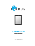
0-7, but the physical package has labels 1-8. The proper labels can be seen in Figure 3.1.
USER_DIP0 controls whether miniboot runs immediately or it spins while waiting for register 13
to be set to 0 before booting the kernel, leaving time for the kernel to be injected into DRAM following
programming of the FPGA. Register 13 would normally be set to 0 using the debug unit.
23
Figure 3.1: Buttons and switches on the DE4
3.4.1
Load a Kernel into DRAM over JTAG
To load the kernel into DDR2 memory, load it at the physical address 0x100000 where miniboot
boot loader expects to find it. miniboot reads the ELF header in order to determine the kernel start
address. You can then use berictl loadbin2 to load the kernel to DDR2 memory starting at address
0x100000 (also see note below about USER_DIP0 and USER_DIP1):
$ cd cherilibs/trunk/tools/debug
$ ./berictl loadbin -z cheribsd-de4-kernel-sdroot.bz2 0x100000
To boot a kernel thus loaded, you must ensure that both USER_DIP0 and USER_DIP1 are on (toward
the top of the board where the USB blaster is connected). USER_DIP0 will cause the processor to spin
in very early boot, waiting for register 13 to be set to 0. This boot operation can be accomplished through
the debug command:
$ ./berictl boot
USER_DIP1 will skip the relocation from flash routine that would overwrite your freshly inserted kernel.
3.4.2
Load a Kernel into Flash from FreeBSD
From FreeBSD you can use dd or the flashit script to load a kernel to flash:
# dd if=kernel of=/dev/map/kernel conv=osync
The safer option using flashit compresses the kernel with bzip2 or gzip, and requires a .md5
file to exist containing the md5 output for the file:
2
Some users may be able to use the faster berictl loaddram command, but it is broken for most
configuration at this time – as it relies on undocumented Altera internals that have changed in recent releases.
24
# ls kernel.bz2*
kernel.bz2 kernel.bz2.md5
# flashit kernel kernel.bz2
At boot, a kernel written to flash will be relocated to DRAM and executed if USER_DIP1 is set to off.
This relocation will occur at power on if USER_DIP0 is off, or when berictl boot is run if it is on.
3.5
Start Kernel Execution
If USER_DIP0 is set to on, then resume the processor after power on/reset:
$ ./berictl boot
If the DIP switch is unset, then boot will proceed as soon as the FPGA is programmed, either using
JTAG or from flash. If all has gone well, you should see kernel boot messages in output from the
console. If you are using the BERI_DE4_MDROOT or CHERI_DE4_MDROOT kernel configuration, a
memory root filesystem will be used; single or multi-user mode should be reached, depending on the
image. If you are using the BERI_DE4_SDROOT or CHERI_DE4_SDROOT kernel configuration, the
SD Card should be used for the root filesystem, and multi-user mode should be reached. Be warned that
the SD-card IP core provided by Altera is extremely slow (100KB/s), and so multi-user boots can take
several minutes.
3.6
Post-Boot Issues
After boot, FreeBSD/BERI is much like any FreeBSD system with a similar set of components. There
are a few issues to keep in mind
• The MDROOT kernels are space limited and have minimal set of tools available.
• Since the root filesystems of MDROOT kernels are stored in memory, all configuration including
ssh keys will be lost at reboot time.
• The Ethernet controllers have no default source of unique MAC addresses and thus default to a
random address that changes on each boot.
3.6.1
Increasing the Size of an SD Card Root Filesystem
After boot, you can extend the filesystem to the size of the SD Card using FreeBSD’s growfs command:
$ growfs -y /dev/altera_sdcard0
Before running this command, make sure your filesystem is backed up or easily replacable.
25
3.6.2
Setting a MAC Address
The Altera Triple-Speed Ethernet (ATSE) devices obtain a unique MAC address from the configuration
area at the beginning of the CFI flash. Unfortunately, all DE4 boards come from the factory with the
same MAC address, so that address has been blacklisted by the driver; instead, a random address is
generated at boot for each interface.
An address can be written to the DE4 using the atsectl command. An address derived from the
factory PPR on the Intel StrataFlash on the DE4 can be written with the command:
$ atsectl -u
The default address has the locally administered bit set and uses the Altera prefix dedicated to this
purpose.
In the Cambridge environment, the decision was made to leave the locally administered bit unset.
This can be accomplished with the command:
$ atsectl -gu
If the board was configured following the DE4 Factory Install Guide v1.0, then an Altera prefixed MAC
without the locally administered bit will have been installed on the DE4.
26
Chapter 4
FreeBSD/BERI Device-Driver Reference
This chapter provides reference information for BERI- and CHERI-specific device drivers and features.
Most device drivers are also documented in man pages in the FreeBSD/BERI distribution.
4.1
Device Drivers for Altera IP Cores
FreeBSD/BERI provides device drivers for a number of useful IP cores and peripheral devices on the
Terasic tPad and Terasic DE4 teaching boards. The drivers are statically linked into the reference BERI
kernels. Because the Avalon bus does not support auto-configuration and device enumeration, these
drivers are also statically configured into the kernel using FDT DTS files. device.hints may also
be used to configure these devices; examples of each are included in this chapter.
4.1.1
Altera JTAG UART
The Altera JTAG device driver implements FreeBSD low-level console and TTY interfaces for the Altera
JTAG UART, which can be connected to using nios2-terminal to provide a system console for
FreeBSD/BERI. This driver assumes that the low-level console JTAG UART will always be configured
at a fixed physical address, and so cannot be configured using FDT or device.hints files. However,
high-level console support is entirely configurable. The device name for the first Altera JTAG UART is
/dev/ttyu0.
Note: the Altera JTAG UART is not associated with the Terasic DE4’s RS232 serial port, which is
currently unsupported in FreeBSD/BERI, and not configured in our reference DE4 design.
Kernel Configuration
device
altera_jtag_uart
FDT
serial@7f000000 {
compatible = "altera,jtag_uart-11_0";
reg = <0x7f000000 0x40>;
interrupts = <0>;
};
serial@7f001000 {
27
compatible = "altera,jtag_uart-11_0";
reg = <0x7f001000 0x40>;
};
serial@7f002000 {
compatible = "altera,jtag_uart-11_0";
reg = <0x7f002000 0x40>;
};
device.hints
#
# Altera JTAG UARTs configured for console, debugging, and
# data putput on the DE4.
#
hint.altera_jtag_uart.0.at="nexus0"
hint.altera_jtag_uart.0.maddr=0x7f000000
hint.altera_jtag_uart.0.msize=0x40
hint.altera_jtag_uart.0.irq=0
hint.altera_jtag_uart.1.at="nexus0"
hint.altera_jtag_uart.1.maddr=0x7f001000
hint.altera_jtag_uart.1.msize=0x40
hint.altera_jtag_uart.2.at="nexus0"
hint.altera_jtag_uart.2.maddr=0x7f002000
hint.altera_jtag_uart.2.msize=0x40
/etc/ttys
# Altera JTAG UART
ttyj0
"/usr/libexec/getty std.115200" xterm
ttyj1
"/usr/libexec/getty std.115200" xterm
ttyj2
"/usr/libexec/getty std.115200" xterm
4.1.2
on
on
on
secure
secure
secure
Generic Avalon Device Driver
The Generic Avalon device driver exports a region of physical memory, which typically represents a
memory-mapped device on the Avalon bus to userspace processes via a device node. User processes can
perform I/O on the device using the POSIX read and write system call APIs, but can also map the
device into virtual memory using the mmap API. Device instances are configured using BERI.hints
entries, which specify the base, length, and mapping properties of the memory region, as well as any I/O
alignment requirements and restrictions (e.g., a read-only, 32-bit access only).
The following example instantiates a berirom device node representing physical memory starting
at 0x7f00a000 and continuing for 20 bytes on the Avalon bus. I/O must be performed with 32-bit
alignment; data may be both read and written using the POSIX file APIs, and may not be memorymapped.
Currently, the avgen device does not support direction of interrupts to userspace components, but
we hope to add this function in the future, in which case it will likely be exposed using the kqueue and
poll APIs.
28
Kernel Configuration
device
altera_avgen
FDT
avgen@0x7f00a000 {
compatible = "sri-cambridge,avgen";
reg = <0x7f00a000 0x14>;
sri-cambridge,width = <4>;
sri-cambridge,fileio = "rw";
sri-cambridge,devname = "berirom";
};
device.hints
hint.altera_avgen.0.at="nexus0"
hint.altera_avgen.0.maddr=0x7f00a000
hint.altera_avgen.0.msize=20
hint.altera_avgen.0.width=4
hint.altera_avgen.0.fileio="rw"
hint.altera_avgen.0.devname="berirom"
4.1.3
Altera University Program SD Card IP Core
This device driver implements FreeBSD block storage device interfaces for the Altera University Program SD Card IP core. Currently, the driver supports only CSD structure 0 SD Cards, limited to 2 GB
in size. This limitation may also apply to the Altera SD Card IP Core. SD Card devices appear in
/dev as they are inserted, and will typically be named /dev/altera_sdcard0. FreeBSD’s GEOM
framework will automatically discover partitions on the disk, causing additional device nodes for those
partitions to appear as well – for example, /dev/altera_sdcard0s1 for the first MBR partition.
Kernel Configuration
device
altera_sdcard
FDT
sdcard@7f008000 {
compatible = "altera,sdcard_11_2011";
reg = <0x7f008000 0x400>;
};
device.hints
hint.altera_sdcardc.0.at="nexus0"
hint.altera_sdcardc.0.maddr=0x7f008000
hint.altera_sdcardc.0.msize=0x400
29
4.1.4
Altera Triple-Speed Ethernet
The atse(4) driver implements a FreeBSD Ethernet interface for the Altera Triple-Speed Ethernet IP
core. The driver currently supports only gigabit Ethernet (no 10/100). Interfaces must be configured in
polling mode. In FreeBSD this may be accomplished with a line like this in /etc/rc.conf. (This
example also causes the interface to be configured using DHCP.)
ifconfig_atse0="polling DHCP"
atse(4) devices are discovered by FDT, but device.hints entries are currently required to properly configure the PHYs for each device.
Kernel Configuration
device
altera_atse
device
device
options
ether
miibus
DEVICE_POLLING
FDT
ethernet@7f007000 {
compatible = "altera,atse";
/* MAC, RX+RXC, TX+TXC. */
reg = <0x7f007000 0x400
0x7f007500 0x8
0x7f007520 0x20
0x7f007400 0x8
0x7f007420 0x20>;
/* RX, TX */
interrupts = <1 2>;
};
ethernet@7f005000 {
compatible = "altera,atse";
/* MAC, RX+RXC, TX+TXC. */
reg = <0x7f005000 0x400
0x7f005500 0x8
0x7f005520 0x20
0x7f005400 0x8
0x7f005420 0x20>;
};
device.hints
#
# Altera Triple-Speed Ethernet MAC (which is present in tPad and DE4
# configurations)
#
hint.atse.0.at="nexus0"
30
hint.atse.0.maddr=0x7f007000
hint.atse.0.msize=0x400
hint.atse.0.tx_maddr=0x7f007400
hint.atse.0.tx_msize=0x8
hint.atse.0.txc_maddr=0x7f007420
hint.atse.0.txc_msize=0x20
hint.atse.0.tx_irq=2
hint.atse.0.rx_maddr=0x7f007500
hint.atse.0.rx_msize=0x8
hint.atse.0.rxc_maddr=0x7f007520
hint.atse.0.rxc_msize=0x20
hint.atse.0.rx_irq=1
#
# Altera Triple-Speed Ethernet MAC (present in tPad and DE4
# configurations) are configured from fdt(4) but PHYs are
# still described in here.
# Currently configured for individual tse_mac cores.
#
hint.e1000phy.0.at="miibus0"
hint.e1000phy.0.phyno=0
hint.e1000phy.1.at="miibus0"
hint.e1000phy.1.phyno=0
hint.e1000phy.2.at="miibus0"
hint.e1000phy.2.phyno=0
hint.e1000phy.3.at="miibus0"
hint.e1000phy.3.phyno=0
4.2
Device Drivers for Terasic Components
FreeBSD/BERI provides device drivers for several devices on the Terasic DE4 and Terasic tPad teaching
boards. As with Altera device drivers, Terasic device drivers are statically linked into the FreeBSD
kernel, and configured using BERI.hints.
4.2.1
Terasic DE4 8-Element LED
The Terasic DE4 device driver implements FreeBSD LED interfaces for the Terasic DE4 8-element
LED, which may be written to as described in the FreeBSD led(4) man page. Device nodes appear in
/dev/led, with names using the scheme de4led_0, de4led_1, and so on.
The following command at the FreeBSD/BERI shell will cause DE4 LED 1 to blink roughly once a
second:
$ echo f9 > /dev/led/de4led_1
Kernel Configuration
device
terasic_de4led
31
FDT
led@7f006000 {
compatible = "sri-cambridge,de4led";
reg = <0x7f006000 0x1>;
};
device.hints
hint.terasic_de4led.0.at="nexus0"
hint.terasic_de4led.0.maddr=0x7f006000
hint.terasic_de4led.0.msize=1
4.2.2
Common Flash Memory Interface
FreeBSD/BERI includes an improved version of the cfi(4) driver that supports Intel, Sharp, and AMD
NOR flash with respect to the Common Flash memory Interface (CFI) standard. The cfi(4) is used to
support to the Intel StrataFlash found on the DE4. The flash is both configured and partitioned using FDT
via the geom_flashmap(4) driver. Partitions are accessable at /dev/<device>s.<label> for
example /dev/cfid0s.os.
Kernel Configuration
device
device
options
cfi
cfid
CFI_SUPPORT_STRATAFLASH
FDT
flash@74000000 {
#address-cells = <1>;
#size-cells = <1>;
compatible = "cfi-flash";
reg = <0x74000000 0x4000000>;
/* Board configuration */
partition@0 {
reg = <0x0 0x20000>;
label = "config";
};
/* Power up FPGA image */
partition@20000 {
reg = <0x20000 0xc00000>;
label = "fpga0";
};
/* Secondary FPGA image (on RE_CONFIGn button) */
partition@C20000 {
reg = <0xc20000 0xc00000>;
32
label = "fpga1";
};
/* Space for operating system use */
partition@1820000 {
reg = <0x1820000 0x027c0000>;
label = "os";
};
/* Second stage bootloader */
parition@3fe0000 {
reg = <0x3fe0000 0x20000>;
label = "boot";
};
};
4.2.3
Flash Partitioning
This section documents use of device.hints to configure regions of the flash as separate /dev/map
partitions via the geom_map(4) driver. We use /dev/map partitions for backwards compatibility and
to provide easy access to regions not defined by the hardware.
Kernel Configuration
device
geom_map
device.hints
# Hardwired location of bitfile
hint.map.0.at="cfid0s.fpga0"
hint.map.0.start=0x00000000
hint.map.0.end=0x00c00000
hint.map.0.name="fpga"
# Kernel in the middle of the operating system parition
hint.map.1.at="cfid0s.os"
hint.map.1.start=0x007e0000
hint.map.1.end=0x01fe0000
hint.map.1.name="kernel"
4.2.4
Cambridge/Terasic Multi-Touch LCD Display (MTL)
The terasic_mtl device driver implements a set of device nodes representing various aspects of the
Terasic MTL as interfaced with using the Cambridge IP core. These device nodes implement POSIX
I/O and memory-mapped interfaces to the register interface, text frame buffer, and pixel frame buffer,
respectively.
Kernel Configuration
device
terasic_mtl
33
FDT
touchscreen@70400000 {
compatible = "sri-cambridge,mtl";
reg = <0x70400000 0x1000
0x70000000 0x177000
0x70177000 0x2000>;
};
device.hints
hint.terasic_mtl.0.at="nexus0"
hint.terasic_mtl.0.reg_maddr=0x70400000
hint.terasic_mtl.0.reg_msize=0x1000
hint.terasic_mtl.0.pixel_maddr=0x70000000
hint.terasic_mtl.0.pixel_msize=0x177000
hint.terasic_mtl.0.text_maddr=0x70177000
hint.terasic_mtl.0.text_msize=0x2000
34