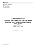
1
CC-Link IE Controller
Network Module
User’s Manual
(Hardware)
QJ71GP21-SX
QJ71GP21S-SX
Thank you for purchasing the Mitsubishi programmable controller
MELSEC-Q series.
Prior to use, please read this and relevant manuals thorougly to fully
understand the product.
MODEL QJ71GP21-SX-U-HW
MODEL
CODE
13JY13
IB(NA)-0800364-D(0804)MEE
© 2007 MITSUBISHI ELECTRIC CORPORATION
SAFETY PRECAUTIONS
(Be sure to read these instructions before use.)
Before using this product, please read this manual and the relevant manuals
introduced in this manual carefully and pay full attention to safety to handle the
product correctly.
The instructions given in this manual are concerned with this product. For the
safety instructions of the programmable controller system, please read the CPU
module user’s manual.
In this manual, the safety instructions are ranked as "DANGER" and "CAUTION".
DANGER
Indicates that incorrect handling may cause
hazardous conditions, resulting in death or severe
injury.
CAUTION
Indicates that incorrect handling may cause
hazardous conditions, resulting in minor or moderate
injury or property damage.
Note that the
CAUTION level may lead to a serious consequence according
to the circumstances.
Always follow the instructions of both levels because they are important to
personal safety.
Please save this manual to make it accessible when required and always forward
it to the end user.
A-1
[DESIGN PRECAUTIONS]
DANGER
For each station’s operating status in the case of a communication error in
the network, refer to CC-Link IE Controller Network Reference Manual. A
malfunction due to a communication error may result in an accident.
To control a running programmable controller (data modification) by
connecting GX Developer to a CPU module or connecting a personal
computer to an intelligent function module, create an interlock circuit on the
sequence program so that the entire system will function safely all the time.
Also, before performing any other controls (e.g. program modification,
operating status change (status control)) to the programmable controller,
read the manual carefully and ensure the safety. Especially, in the case of
controlling a remotely-located programmable controller from an external
device, a programmable controller side problem could not be resolved
immediately due to data communication failure. To prevent this, establish
corrective procedures for communication failure between the external device
and the programmable controller CPU, as well as creating an interlock circuit
on the program.
Laser diodes are used in the optical transceivers of the CC-Link IE controller
network. The class of these laser diodes is Class 1.
CAUTION
Do not install the control lines and/or communication cables together with the
main circuit or power cables, and also do not bring them close to each other.
Keep a distance of 100mm (3.94 inch) or more between them. Failure to do
so may cause a malfunction due to noise.
A-2
[INSTALLATION PRECAUTIONS]
CAUTION
Use the programmable controller in the environment conditions given in the
general specifications of the User's Manual for the CPU module used. Failure
to do so may cause an electric shock, fire, malfunction, or damage to or
deterioration of the product.
While pressing the installation lever located at the bottom of the module,
insert the module fixing projection into the fixing hole in the base unit to
mount the module. Incorrect module mounting may cause a malfunction,
failure, or drop of the module. In an environment of frequent vibrations,
secure the module with the screw. The screw must be tightened within the
specified torque range. If the screw is too loose, it may cause a drop, short
circuit, or malfunction. Excessive tightening may damage the screw and/or
the module, resulting in a drop, short circuit or malfunction.
Be sure to shut off all phases of the external power supply used by the
system before mounting or removing the module. Failure to do so may
damage the module.
Do not directly touch any conductive part or electronic component of the
module. Doing so may cause a malfunction or failure of the module.
[WIRING PRECAUTIONS]
DANGER
Be sure to shut off all phases of the external power supply before installation
or wiring. Failure to do so may result in an electric shock or damage to the
product.
A-3
[WIRING PRECAUTIONS]
CAUTION
Always ground the FG terminal to the protective ground conductor. Failure to
do so may cause a malfunction.
Verify the rated voltage and pin-out, and connect the external power supply
cable properly. Connecting a power supply with a different voltage rating or
faulty wiring may cause a fire or failure.
Terminal screws must be tightened with the specified torque. If a screw is
loose, it may cause a short circuit, fire or malfunction.
Be careful to prevent foreign matter such as dust or wire chips from entering
the module. Failure to do so may cause a fire, failure or malfunction.
Be sure to place the communication cables or power cables in a duct or
clamp them. If not, dangling cables may swing or inadvertently be pulled,
resulting in damage to the module or cables, or malfunctions due to poor
cable connection.
When disconnecting a communication cable or a power cable from the
module, do not pull the cable part. For a cable with connectors, hold the
connector by hand and disconnect it from the module. For a cable connected
to a terminal block, loosen the terminal block screws and disconnect the
cable from the module. Pulling a cable that is still connected to the module
may cause a malfunction or damage the module and/or the cable.
A protective film is attached to the module top to prevent foreign matter such
as wire chips from entering the module during wiring. Do not remove the film
during wiring. Be sure to remove it for heat dissipation before system
operation.
A-4
Revisions
* The manual number is given on the bottom right of the cover.
Print Date
Jan., 2007
*Manual Number
IB(NA)-0800364-A
Apr. 2007
IB(NA)-0800364-B
Revision
First edition
Model added
QJ71GP21S-SX
Partially revised
SAFETY PRECAUTIONS, Chapter 1 and 2,
Section 3.1, Chapter 4, Section 5.1, Chapter 6
Added
Jan., 2008
IB(NA)-0800364-C
Section 6.2
The entire manual was reviewed since the existing
MELSECNET/G network module has been
integrated into the CC-Link IE controller network
module.
Partially revised
Section 5.1
Apr., 2008
IB(NA)-0800364-D
Partially revised
Compliance with The EMC and Low Voltage
Directives, Chapter 2
This manual confers no industrial property rights or any rights of any other kind, nor does it
confer any patent licenses. Mitsubishi Electric Corporation cannot be held responsible for any
problems involving industrial property rights which may occur as a result of using the contents
noted in this manual.
© 2007 MITSUBISHI ELECTRIC CORPORATION
A-5
CONTENTS
1. OVERVIEW..................................................................................................... 1
2. PERFORAMNCE SPECIFICATIONS ............................................................. 1
3. MOUNTING AND INSTALLATION ................................................................. 4
3.1 Handling Precautions .............................................................................. 4
3.2 Installation Environment .......................................................................... 4
4. PART NAMES................................................................................................. 5
5. WIRING........................................................................................................... 8
5.1 Connecting Optical Fiber Cables............................................................. 8
5.2 Wiring Precautions ................................................................................... 9
6. EXTERNAL DIMENSIONS ........................................................................... 10
6.1 QJ71GP21-SX........................................................................................ 10
6.2 QJ71GP21S-SX ..................................................................................... 11
A-6
Manuals
The following table lists the manual on this product.
You can order it as necessary.
Relevant Manual
Manual name
CC-Link IE Controller Network Reference Manual
Manual No.
(Model code)
SH-080668ENG
(13JV16)
Compliance with the EMC and Low Voltage Directives
(1) For programmable controller system
To configure a system meeting the requirements of the EMC and
Low Voltage Directives when incorporating the Mitsubishi
programmable controller (EMC and Low Voltage Directives
compliant) into other machinery or equipment, refer to Chapter 9
"EMC AND LOW VOLTAGE DIRECTIVES" of the QCPU User's
Manual (Hardware Design, Maintenance and Inspection).
The CE mark, indicating compliance with the EMC and Low Voltage
Directives, is printed on the rating plate of the programmable
controller.
(2) For the product
No additional measures are necessary for the compliance of this
product with the EMC and Low Voltage Directives.
A-7
1. OVERVIEW
This manual explains how to install and connect the QJ71GP21-SX or
QJ71GP21S-SX CC-Link IE controller network module (hereinafter
referred to as CC-Link IE controller network module).
(Packing list)
Table 1.1 Packing list
Model
Product name
QJ71GP21-SX CC-Link IE controller network
module
QJ71GP21S-SX CC-Link IE controller network
QJ71GP21S-SX
module (with external power supply function)
QJ71GP21-SX
Quantity
1
1
2. PERFORAMNCE SPECIFICATIONS
The following describes the performance specifications of the CC-Link
IE controller network module.
For general specifications of the CC-Link IE controller network module,
refer to the following manual.
QCPU User's Manual (Hardware Design, Maintenance and
Inspection)
Table 2.1 Performance specifications
Item
LB
Max. link points
per network
LW
LX
LY
LB
LW
Max. link points
per station
LX
LY
Transient transmission
capacity
Communication speed
Specification
QJ71GP21-SX
QJ71GP21S-SX
32K points (32768 points, 4KB)
(Basic model QCPU or safety CPU: 16K points (16384 points, 2KB))
128K points (131072 points, 256KB)
(Basic model QCPU or safety CPU: 16K points (16384 points,
32KB))
8K points (8192 points, 1KB)
8K points (8192 points, 1KB)
16K points (16384 points, 2KB)
16K points (16384 points, 32KB)
8K points (8192 points, 1KB)
8K points (8192 points, 1KB)
Up to 1920 bytes
1Gbps
1
Table 2.1 Performance specifications (Continued)
Item
Number of stations per
network
Connection cable
Overall cable distance
Station-to-station
distance (Max.)
Max. number of
networks
Max. number of groups
Transmission path
Optical fiber
specifications
Standard
Transmission
loss (max.)
Transmission
band (min.)
Connector specifications
Standard
Connection
loss
Polished
surface
Number of occupied I/O
points
Voltage
Current
Terminal
screw size
Applicable
solderless
terminal
External Applicable
wire size
power
Tightening
supply
torque
Allowable
momentary
power failure
time
Specification
QJ71GP21-SX
QJ71GP21S-SX
When Universal model QCPU is used for control station: 120
(Control station: 1, Normal station: 119) *1
When any other than Universal model QCPU is used for control
station: 64 (Control station: 1, Normal station: 63) *2
Optical fiber cable (Multi-mode fiber) (
CC-Link IE Controller
Network Reference Manual)
66000m (When 120 stations are connected)
550m (Core/Clad = 50/125 (
m))
239
32
Duplex loop
1000BASE-SX(MMF) optical fiber cable
IEC60793-2-10 Types A1a.1 (50/125
3.5 (dB/km) or less (
m multimode)
= 850nm)
500 (MHz•km) or more (
= 850nm)
Duplex LC connector
IEC61754-20: Type LC connector
0.3 (dB) or less
PC (Physical Contact) polishing
32 (Intelli.: 32 points) *3
48 (I/O assignment: Empty first
half: 16 points, Latter half: 32
points for intelli.) *3 *4
20.4V to 31.2V DC
0.28A
M3
R1.25-3
No external power supply
function
0.3 to 1.25mm2
0.42 to 0.58N•m
1ms (Level PS1)
By noise simulator of 500Vp-p
noise voltage, 1 s noise width,
and 25 to 60Hz noise frequency
Noise
immunity
2
Table 2.1 Performance specifications (Continued)
Specification
Item
Internal current
consumption (5V DC)
External dimensions
Weight
*1
QJ71GP21-SX
QJ71GP21S-SX
0.85A
0.90A
98 (H) x 27.4 (W) x 90 (D) [mm]
0.18kg
98 (H) x 55.2 (W) x 90 (D) [mm]
0.28kg
A Universal model QCPU can be set to a station No. within the range of No.1
to No.120.
For a module other than Universal model QCPUs, station No.1 to No.64 can
be set.
*2
A station with a Basic model QCPU or safety CPU operates as a normal
*3
All I/O signals of the CC-Link IE controller network module are used by the
*4
Two I/O slots are occupied.
station. (It cannot be set to a control station.)
system. (Use prohibited)
In the Start I/O No. field of Network parameters, set a value obtained by
adding 10H to the I/O No. of the module-installed slot. Note that 0 point can
be set instead of 16 points for the first half in I/O assignment of Network
parameters.
(Example) When the module is installed to slot 0, set 10H to Start I/O No.
(When 0 point is set to slot 0 in I/O assignment, set 0H to Start I/O No.)
3
3. MOUNTING AND INSTALLATION
3.1 Handling Precautions
This section describes precautions for handling the CC-Link IE
controller network module itself.
(1) Since the module case is made of resin, do not drop the module or
apply a strong impact to it.
(2) Do not remove the printed-circuit board of the module from the
case.
Doing so will cause failure.
(3) Be careful to prevent foreign matter such as dust or wire chips from
entering the module. Failure to do so may cause a fire, failure or
malfunction.
(4) A protective film is attached to the module top to prevent foreign
matter such as wire chips from entering the module during wiring.
Do not remove the film during wiring.
Be sure to remove it for heat dissipation before system operation.
(5) Before handling the module, touch a grounded metal object to
discharge the static electricity from the human body.
Not doing so may cause a failure or malfunction of the module.
(6) Tighten the module fixing screws or terminal screws within the
following torque range.
Table 3.1 Screw tightening torque
Screw
Module fixing screw (M3 screw)*1
Terminal screw on external power supply
terminal block (M3 screw)
*1
Tightening torque range
0.36 to 0.48N•m
0.42 to 0.58N•m
The module can be easily fixed onto the base unit using the hook at the top
of the module.
However, it is recommended to secure the module with the module fixing
screw if the module is subject to significant vibration or shock.
3.2 Installation Environment
For details, refer to the user's manual for the CPU module used.
4
4. PART NAMES
This section explains the names of each part of the CC-Link IE
controller network module.
QJ71GP21-SX
QJ71GP21S-SX
1)
1)
2)
3)
2)
4)
3)
Figure 4.1 CC-Link IE controller network module appearance
Table 4.1 Names of parts
No.
1)
2)
3)
4)
Name
Description
Indicates the operating status of the CC-Link IE controller
network module. (
(1) in this section)
Used to connect an optical fiber cable to the CC-Link IE
controller network module.
IN connector
(The cable is connected to OUT connector of another station)
(
(3) in this section)
Used to connect an optical fiber cable to the CC-Link IE
controller network module.
OUT connector
(The cable is connected to IN connector of another station)
(
(3) in this section)
External power
Connects a cable for supplying external power to the CC-Link
supply terminal block IE controller network module.
Indicator LED
5
(1) Indicator LEDs
QJ71GP21-SX
QJ71GP21S-SX
QJ71GP21-SX
S 1
T.
N
O.
X100
QJ71GP21S-SX
1
1
RUN
PRM
2
2
MODE
D LINK
4
4
SD
8
8
ERR.
10
1
S 1
T.
N
O.
RD
EXT.PW
X100
1
1
RUN
PRM
2
2
MODE
D LINK
4
4
SD
8
8
ERR.
10
1
RD
Figure 4.2 Indicator LEDs
Table 4.2 LED indication
Name
RUN
MODE
PRM
D LINK
ERR.
SD
RD
1 100
1,2,4,8 10
1,2,4,8 1
EXT.PW
*1
LED status *1
ON, green
OFF
ON, green
Flashing, green
OFF
ON, green
OFF
ON, green
Flashing, green
OFF
ON, red
Description
Operating normally
Hardware fault or watchdog timer error
Online mode
Test mode
Offline mode
Operating as a Control station
Operating as a Normal station
Data link in operation (Cyclic transmission operated)
Data link in operation (Cyclic transmission stopped)
Data link not in operation (Disconnected from network)
• Received data are erroneous.(Receive frame error)
• A frame error above a certain level has occurred
between stations.
• The Control station or a station number is duplicated.
• Cable disconnection, or incorrect cable connection
between OUT and IN
• Network parameters are corrupted, or some settings
(Reserved station specification, Total number of
stations, Network No, etc.) are inconsistent between the
Control and Normal stations.
Normal status
Sending data
Not sending data
Receiving data
Not receiving data
OFF
N, green
OFF
ON, green
OFF
ON, green
The station No. is set. (
(2) in this section)
(Numeric display)
OFF
No station No. is set.
External power supplied (Own station power status
ON, green
(SB0042) is ON.)
External power not supplied (Own station power status
OFF
(SB0042) is OFF.)
When the CPU module is reset, the LEDs other than the EXT.PW LED turn
OFF.
6
(2) Station No. setting
Station No. of the CC-Link IE controller network module is
indicated.
(Example) When indicating station No.15
1
1
4
X100 10
1
10 + 5 = 15
Figure 4.3 Example of station No. setting indication
(3) IN and OUT connectors
IN
Forward loop, receiving
IN
Reverse loop, sending
OUT Reverse loop, receiving
OUT Forward loop, sending
Figure 4.4 IN and OUT connectors
7
5. WIRING
5.1 Connecting Optical Fiber Cables
(1) Connection method
Connect an optical fiber cable between OUT and IN as shown
below.
Note that there is no need to connect the cables in the order of
station numbers.
CC-Link IE controller network module
Normal station
Station No.2
Control station
Station No.1
IN
IN
OUT
Normal station
Station No.n
OUT
IN
OUT
Figure 5.1 Connection method
(2) Connecting the optical fiber cable
Connection
CC-Link IE controller
MELSECNET/G
module
network module
Turn the power OFF.
Module-side connector
Connect the cable-side connector to
the module-side connector, paying
attention to the orientation.
Push it until a "click" is heard.
Cable-side connector
Connector hook
Lightly pull it to check that it is
securely connected.
Completed
Figure 5.2 Connecting the optical fiber cable
(3) Disconnecting the optical fiber cable
Disconnection
CC-Link IE controller
MELSECNET/G
module
network module
Turn the power OFF.
Press the connector hook to
disconnect the cable.
Cable-side connector
Module-side
connector
Completed
Connector hook
Figure 5.3 Disconnecting the optical fiber cable
8
n 120
5.2 Wiring Precautions
(a) Use the optical fiber cable described in the following manual.
CC-Link IE Controller Network Reference Manual
(b) There are restrictions on the bending radius of the optical fiber
cable.
For details, check the specifications of the cable to be used.
(c) When handling an optical fiber cable, do not touch the optical
fiber core of the cable-side or module-side connector, and
protect it from dirt or dust.
If oil from your hand, dirt or dust is attached to the core, it can
increase transmission loss, arising a problem in data link.
(d) When connecting or disconnecting an optical fiber cable, hold
the connector part of the cable.
(e) Make a full connection between the cable-side and moduleside connectors until a "click" can be heard.
9
6. EXTERNAL DIMENSIONS
98 (3.86)
6.1 QJ71GP21-SX
90 (3.54)
4.5 (0.18)
Figure 6.1 External dimensions
10
27.4 (1.08)
(Unit: mm (inch))
98 (3.86)
6.2 QJ71GP21S-SX
90 (3.54)
11
(0.43)
Figure 6.2 External dimensions
55.2 (2.17)
(Unit: mm (inch))
Ethernet is a trademark of Xerox Co., Ltd. in the United States.
Other company names and product names used in this document are
trademarks or registered trademarks of respective owners.
11
Warranty
Mitsubishi will not be held liable for damage caused by factors found not to be the cause of
Mitsubishi; machine damage or lost profits caused by faults in the Mitsubishi products; damage,
secondary damage, accident compensation caused by special factors unpredictable by
Mitsubishi; damages to products other than Mitsubishi products; and to other duties.
For safe use
• This product has been manufactured as a general-purpose part for general industries, and
has not been designed or manufactured to be incorporated in a device or system used in
purposes related to human life.
• Before using the product for special purposes such as nuclear power, electric power,
aerospace, medicine or passenger movement vehicles, consult with Mitsubishi.
• This product has been manufactured under strict quality control. However, when installing the
product where major accidents or losses could occur if the product fails, install appropriate
backup or failsafe functions in the system.
Country/Region Sales office/Tel
U.S.A
Mitsubishi Electric Automation Inc.
500 Corporate Woods Parkway Vernon
Hills, IL 60061, U.S.A.
Tel : +1-847-478-2100
Brazil
MELCO-TEC Rep. Com.e Assessoria
Tecnica Ltda.
Rua Correia Dias, 184,
Edificio Paraiso Trade Center-8 andar
Paraiso, Sao Paulo, SP Brazil
Tel : +55-11-5908-8331
Germany
Mitsubishi Electric Europe B.V. German
Branch
Gothaer Strasse 8 D-40880 Ratingen,
GERMANY
Tel : +49-2102-486-0
U.K
Mitsubishi Electric Europe B.V. UK
Branch
Travellers Lane, Hatfield, Hertfordshire.,
AL10 8XB, U.K.
Tel : +44-1707-276100
Italy
Mitsubishi Electric Europe B.V. Italian
Branch
Centro Dir. Colleoni, Pal. Perseo-Ingr.2
Via Paracelso 12, I-20041 Agrate Brianza.,
Milano, Italy
Tel : +39-039-60531
Spain
Mitsubishi Electric Europe B.V. Spanish
Branch
Carretera de Rubi 76-80,
E-08190 Sant Cugat del Valles,
Barcelona, Spain
Tel : +34-93-565-3131
France
Mitsubishi Electric Europe B.V. French
Branch
25, Boulevard des Bouvets, F-92741
Nanterre Cedex, France
TEL: +33-1-5568-5568
South Africa
Circuit Breaker Industries Ltd.
Private Bag 2016, ZA-1600 Isando,
South Africa
Tel : +27-11-928-2000
Country/Region Sales office/Tel
Hong Kong
Mitsubishi Electric Automation
(Hong Kong) Ltd.
10th Floor, Manulife Tower, 169 Electric
Road, North Point, Hong Kong
Tel : +852-2887-8870
China
Mitsubishi Electric Automation
(Shanghai) Ltd.
4/F Zhi Fu Plazz, No.80 Xin Chang Road,
Shanghai 200003, China
Tel : +86-21-6120-0808
Taiwan
Setsuyo Enterprise Co., Ltd.
6F No.105 Wu-Kung 3rd.Rd, Wu-Ku
Hsiang, Taipei Hsine, Taiwan
Tel : +886-2-2299-2499
Korea
Mitsubishi Electric Automation Korea Co., Ltd.
1480-6, Gayang-dong, Gangseo-ku
Seoul 157-200, Korea
Tel : +82-2-3660-9552
Singapore
Mitsubishi Electric Asia Pte, Ltd.
307 Alexandra Road #05-01/02, Mitsubishi
Electric Building, Singapore 159943
Tel : +65-6470-2460
Thailand
Mitsubishi Electric Automation (Thailand)
Co., Ltd.
Bang-Chan Industrial Estate No.111
Moo 4, Serithai Rd, T.Kannayao,
A.Kannayao, Bangkok 10230 Thailand
Tel : +66-2-517-1326
Indonesia
P.T. Autoteknindo Sumber Makmur
Muara Karang Selatan, Block A/Utara
No.1 Kav. No.11 Kawasan Industri
Pergudangan Jakarta - Utara 14440,
P.O.Box 5045 Jakarta, 11050 Indonesia
Tel : +62-21-6630833
India
Messung Systems Pvt, Ltd.
Electronic Sadan NO:III Unit No15,
M.I.D.C Bhosari, Pune-411026, India
Tel : +91-20-2712-3130
Australia
Mitsubishi Electric Australia Pty. Ltd.
348 Victoria Road, Rydalmere,
N.S.W 2116, Australia
Tel : +61-2-9684-7777
HEAD OFFICE : TOKYO BUILDING, 2-7-3 MARUNOUCHI, CHIYODA-KU, TOKYO 100-8310, JAPAN
NAGOYA WORKS : 1-14, YADA-MINAMI 5-CHOME, HIGASHI-KU, NAGOYA, JAPAN
When exported from Japan, this manual does not require application to the Ministry
of Economy, Trade and Industry for service transaction permission.
Specifications subject to change without notice.
Printed in Japan on recycled paper.