1
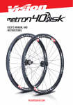
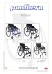
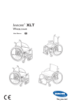
52
chapter
Wheel"Alignment"
Service"
chapter"52""
Wheel"Alignment"Service"
FIGURE 52.1 Positive camber. The dotted line represents true vertical and the solid line represents the
angle of the wheel.!
chapter"52""
Wheel"Alignment"Service"
FIGURE 52.2 Positive (+) caster.!
1"
chapter"52""
Wheel"Alignment"Service"
FIGURE 52.3 Toe-in, also called positive (+) toe.!
chapter"52""
Wheel"Alignment"Service"
FIGURE 52.4 Typical tire wear chart as found in a service manual. Abnormal tire wear usually indicates a
fault in a steering or suspension component that should be corrected or replaced before an alignment is
performed.!
chapter"52""
Wheel"Alignment"Service"
FIGURE 52.5 Measuring points for ride (trim) height vary by manufacturer.!
2"
chapter"52""
Wheel"Alignment"Service"
FIGURE 52.6 Measuring to be sure the left and right sides of the vehicle are of equal height. If this
measurement is not equal side to side by as little as 1/8 inch (3 mm), it can affect the handling of the
vehicle.!
chapter"52""
Wheel"Alignment"Service"
FIGURE 52.7 The bulge in this tire was not noticed until it was removed from the vehicle as part of a
routine brake inspection. After replacing this tire, the vehicle stopped pulling and vibrating.!
chapter"52""
Wheel"Alignment"Service"
FIGURE 52.8 Equal outer CV joint angles produce equal steer torque (toe-in). If one side receives more
engine torque, that side creates more toe-in and the result is a pull toward one side, especially during
acceleration.!
3"
chapter"52""
Wheel"Alignment"Service"
FIGURE 52.9 Broken or defective engine or transaxle mounts can cause the powertrain to sag, causing
unequal drive axle shaft CV joint angles.!
chapter"52""
Wheel"Alignment"Service"
CHART 52.1!
chapter"52""
Wheel"Alignment"Service"
FIGURE 52.10 This alignment chart indicates the preferred setting with a plus or minus tolerance.!
4"
chapter"52""
Wheel"Alignment"Service"
FIGURE 52.11 Using the alignment rack hydraulic jacks, raise the tires off the rack so that they can be
rotated as part of the compensating process.!
chapter"52""
Wheel"Alignment"Service"
FIGURE 52.12 An optical-type wheel sensor. Compensation is achieved by simply rolling the vehicle
backward and forward.!
chapter"52""
Wheel"Alignment"Service"
FIGURE 52.13 If toe for an oversize tire is set by distance, the toe angle will be too small. Toe angle is the
same regardless of tire size.!
5"
chapter"52""
Wheel"Alignment"Service"
FIGURE 52.14 The protractor scale on the front turn plates allows the technician to test the turning radius
by turning one wheel to an angle specified by the manufacturer and observing the angle of the other front
wheel. Most newer alignment machines can display turning angle based on sensor readings, and
therefore the protractor scale on the turn plate is not needed or used. !
chapter"52""
Wheel"Alignment"Service"
FIGURE 52.15 By checking the SAI, camber, and included angle, a damaged suspension component can
be determined by using this chart.!
chapter"52""
Wheel"Alignment"Service"
FIGURE 52.16 In this example, both SAI and camber are far from being equal side to side. However, both
sides have the same included angle, indicating that the frame may be out of alignment. An attempt to align
this vehicle by adjusting the camber on both sides with either factory or aftermarket kits would result in a
totally incorrect alignment. !
6"
chapter"52""
Wheel"Alignment"Service"
FIGURE 52.17 This is the same vehicle as shown in Figure 52–16, except now the frame (cradle) has
been shifted over and correctly positioned. Notice how both the SAI and camber become equal without
any other adjustments necessary. !
chapter"52""
Wheel"Alignment"Service"
FIGURE 52.18 Geometric-centerline-type alignment sets the front toe readings based on the geometric
centerline of the vehicle and does not consider the thrust line of the rear wheel toe angles. !
chapter"52""
Wheel"Alignment"Service"
FIGURE 52.19 Thrust line alignment sets the front toe parallel with the rear-wheel toe.!
7"
chapter"52""
Wheel"Alignment"Service"
FIGURE 52.20 Four-wheel alignment corrects for any rearwheel toe to make the thrust line and the
geometric centerline of the vehicle both the same.!
chapter"52""
Wheel"Alignment"Service"
FIGURE 52.21 The rear camber is adjustable on this vehicle by rotating the eccentric cam and watching
the alignment machine display.!
chapter"52""
Wheel"Alignment"Service"
FIGURE 52.22 Some vehicles use a threaded fastener similar to a tie rod to adjust camber on the rear
suspension.!
8"
chapter"52""
Wheel"Alignment"Service"
FIGURE 52.23 Aftermarket alignment parts or kits are available to change the rear camber.!
chapter"52""
Wheel"Alignment"Service"
FIGURE 52.24 Full-contact plastic or metal shims can be placed between the axle housing and the brake
backing plate to change rear camber, toe, or both.!
chapter"52""
Wheel"Alignment"Service"
FIGURE 52.25 The rear toe was easily set on this vehicle. The adjusting nuts were easy to get to and turn.
Adjusting rear toe is not this easy on every vehicle.!
9"
chapter"52""
Wheel"Alignment"Service"
FIGURE 52.26 By moving various rear suspension members, the rear toe can be changed.!
chapter"52""
Wheel"Alignment"Service"
FIGURE 52.27 The use of these plastic or metal shims requires that the rear wheel as well as the hub
assembly and/or backing plate be removed. Proper torque during reassembly is critical to avoid damage
to the shims. !
chapter"52""
Wheel"Alignment"Service"
FIGURE 52.28 Many struts allow camber adjustment at the strut-to-knuckle fasteners. Here a special tool
is being used to hold and move the strut into alignment with the fasteners loosened. Once the desired
camber angle is achieved, the strut nuts are tightened and the tool is removed. !
10"
chapter"52""
Wheel"Alignment"Service"
FIGURE 52.29 Some struts require modification of the upper mount for camber adjustment.!
chapter"52""
Wheel"Alignment"Service"
FIGURE 52.30 An example of the many methods that are commonly used to adjust front caster and
camber.!
chapter"52""
Wheel"Alignment"Service"
FIGURE 52.31 If there is a nut on both sides of the strut rod bushing, then the length of the rod can be
adjusted to change caster.!
11"
chapter"52""
Wheel"Alignment"Service"
FIGURE 52.32 Placing shims between the frame and the upper control arm pivot shaft is a popular
method of alignment for many SLA suspensions. Both camber and caster can be easily changed by
adding or removing shims.!
chapter"52""
Wheel"Alignment"Service"
FIGURE 52.33 The general rule of thumb is that a 1/8 inch shim added or removed from both shim
locations changes the camber angle about 1/2 degree. Adding or removing a 1/8 inch shim from one
shim location changes the caster by about 1/4 degree. !
chapter"52""
Wheel"Alignment"Service"
FIGURE 52.34 Some SLA-type suspensions use slotted holes for alignment angle adjustments. When the
pivot shaft bolts are loosened, the pivot shaft is free to move unless held by special clamps as shown. By
turning the threaded portion of the clamps, the camber and caster can be set and checked before
tightening the pivot shaft bolts. !
12"
chapter"52""
Wheel"Alignment"Service"
FIGURE 52.35 When the nut is loosened and the bolt on the eccentric cam is rotated, the upper control
arm moves in and out. By adjusting both eccentric cams, both camber and caster can be adjusted. !
chapter"52""
Wheel"Alignment"Service"
FIGURE 52.36 Typical shim alignment chart. As noted, 1/8 inch (0.125) shims can be substituted for the
0.120 inch shims; 1/32 inch (0.0625) shims can be substituted for the 0.060 inch shims; and 1/32 inch
(0.03125) shims can be substituted for the 0.030 inch shims.!
chapter"52""
Wheel"Alignment"Service"
FIGURE 52.37 Many procedures for setting toe specify that the steering wheel be held in the straight-
ahead position using a steering wheel lock, as shown. One method recommended by Hunter Engineering
sets toe without using a steering wheel lock. !
13"
chapter"52""
Wheel"Alignment"Service"
FIGURE 52.38 Adjusting toe by rotating the tie rod on a vehicle equipped with rack-and-pinion steering.!
chapter"52""
Wheel"Alignment"Service"
FIGURE 52.39 Toe is adjusted on a parallelogram-type steering linkage by turning adjustable tie rod
sleeves. Special tie rod sleeve adjusting tools should be used that grip the slot in the sleeve and will not
crush the sleeve while it is being rotated.!
chapter"52""
Wheel"Alignment"Service"
FIGURE 52.40 Special tie rod adjusting tools should be used to rotate the tie rod adjusting sleeves. The
tool grips the slot in the sleeve and allows the service technician to rotate the sleeve without squeezing or
damaging the sleeve. !
14"
chapter"52""
Wheel"Alignment"Service"
FIGURE 52.41 Most vehicles have alignment marks made at the factory on the steering shaft and steering
wheel to help the service technician keep the steering wheel in the center position.!
chapter"52""
Wheel"Alignment"Service"
FIGURE 52.42 A puller being used to remove a steering wheel after the steering wheel retaining nut has
been removed.!
chapter"52""
Wheel"Alignment"Service"
FIGURE 52.43 The toe-in on the right wheel creates a turning force toward the right.!
15"
chapter"52""
Wheel"Alignment"Service"
FIGURE 52.44 An aftermarket camber shim can be added to change the front camber on this Honda.!
chapter"52""
Wheel"Alignment"Service"
FIGURE 52.45 An aftermarket kit for this Ford is installed at the top of the strut tower and allows more
camber and caster adjustment than is possible with the factory adjustment.!
chapter"52""
Wheel"Alignment"Service"
FIGURE 52.46 A typical tire temperature pyrometer. The probe used is a needle that penetrates about 1/4
inch (7 mm) into the tread of the tire for most accurate readings.!
16"
chapter"52""
Wheel"Alignment"Service"
FIGURE 52.47 Jig holes used at the assembly plant to locate suspension and drivetrain components.
Check service information for the exact place to measure and the specified dimensions when checking for
body or frame damage. !
chapter"52""
Wheel"Alignment"Service"
UNFIGURE 52.1 Begin the alignment procedure by first driving the vehicle onto the alignment rack as
straight as possible. !
chapter"52""
Wheel"Alignment"Service"
UNFIGURE 52.2 Position the front tires in the center of the turn plates. These turn plates can be moved
inward and outward to match a vehicle of any width.!
17"
chapter"52""
Wheel"Alignment"Service"
UNFIGURE 52.3 Raise the vehicle and position the alignment rack following the rack manufacturer s
instructions.!
chapter"52""
Wheel"Alignment"Service"
UNFIGURE 52.4 Check and adjust tire pressures and perform the pre alignment checks necessary to be
assured of proper alignment.!
chapter"52""
Wheel"Alignment"Service"
UNFIGURE 52.5 Select the exact vehicle on the alignment machine.!
18"
chapter"52""
Wheel"Alignment"Service"
UNFIGURE 52.6 Securely"mount"the"alignment"heads"or"target"wheels.!
chapter"52""
Wheel"Alignment"Service"
UNFIGURE 52.7 If mounting a transmitter-type alignment head, be sure to attach the retaining wire to the
tire valve.!
chapter"52""
Wheel"Alignment"Service"
UNFIGURE 52.8 After installation of the heads, follow the specified procedure for compensation, which
allows accurate alignment readings.!
19"
chapter"52""
Wheel"Alignment"Service"
UNFIGURE 52.9 Rolling compensation is used on machines that use lasers and wheel targets.!
chapter"52""
Wheel"Alignment"Service"
UNFIGURE 52.10 An alignment reading is displayed even though caster has not yet been measured. The
readings marked in red indicate that they are not within specifications.!
chapter"52""
Wheel"Alignment"Service"
UNFIGURE 52.11 Before performing a caster sweep, install a brake pedal depressor to keep the front
wheels from rotating when the steering wheel is turned.!
20"
chapter"52""
Wheel"Alignment"Service"
UNFIGURE 52.12 Perform the caster sweep by turning the front wheels inward, and then outward
following the instructions on the screen.!
chapter"52""
Wheel"Alignment"Service"
UNFIGURE 52.13 Most alignment machines will display where to make the alignment correction and will
often include drawings and live action videos that show the procedure.!
chapter"52""
Wheel"Alignment"Service"
UNFIGURE 52.14 The rear toe is being adjusted by rotating the eccentric cam on the lower control arm
while watching the display.!
21"
chapter"52""
Wheel"Alignment"Service"
UNFIGURE 52.15 The alignment machine display indicates that front caster is not a factory-adjustable
angle.!
chapter"52""
Wheel"Alignment"Service"
UNFIGURE 52.16 Adjusting the front toe on this vehicle involves loosening the jam nut (left wrench) and
rotating the tie rod using the right wrench.!
chapter"52""
Wheel"Alignment"Service"
UNFIGURE 52.17 One last adjustment of the left front toe is needed to achieve a perfect alignment. The
final alignment reading can be printed and attached to the work order.!
22"
chapter"52""
Wheel"Alignment"Service"
UNFIGURE 52.18 After disconnecting all of the attachments, reinstalling the valve caps, and removing the
steering wheel holder, the vehicle should be test-driven to check for proper alignment before returning it to
the customer. !
23"