1
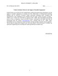
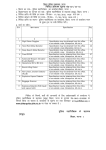
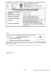
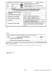
National Institute of Electronics and Information Technology, Gorakhpur Centre
A Scientific Body of Dept. of Eectronics and Information Technology, Ministry of
Comm. & Information Technology, Govt. of India
M.M.M Technical University Campus, Gorakhpur-273010(U.P.)
Phone no. 0551- 2273371, Fax 2273873
Website: www.nielitgkp.edu.in, www.eprocure.gov.in
Procurement of Solar Panel System
On behalf of the Director, NIELIT Gorakhpur Quotations are invited from interested parties for
the supply and installation of Solar Panel System(Solar street light and Solar Lantern) and
Measuring Instruments.The Specifications, terms and conditions are available on NIELIT
Gorakhpur website www.nielitgkp.edu.in or www.eprocure.gov.in Last date for receiving of
quotations is 05.12.2014 at 3.00 P.M. and tender will be conducted on 05.12.2014 at 4.00 P.M.
Advt. No. NIELIT/Gkp/224/05/2014
Deputy Director
NATIONAL INSTITUTE OF ELECTRONICS AND INFORMATION TECHNOLOGY-GORAKHPUR
jk’Vªh; bysDVªkWfudh ,oa lwpuk izks|ksfxdh laLFkku] xksj[kiqj
A Scientific Body of Dept. of Eectronics and Information Technology,
Ministry of Comm. & Information Technology, Govt. of India
(bysDVªkWfudh ,oa lwpuk izkS|ksfxdh foHkkx] lapkj ,oa lwpuk izkS|ksfxdh ea=ky;] Hkkjr ljdkj dh ,d Lok;Rr oSKkfud laLFkk)
M.M.M.University of Technology Campus, Gorakhpur-273010 (U.P.)
e0 eks0 ek0 bathfu;fjax dkyst ifjlj ] Xkksj[kiqj ¼m0iz0½ -273010
Phone no./ Qksu ua0 0551- 2273371, Fax/ QSDl 2273873
Website: www.nielitgkp.edu.in, www.eprocure.gov.in
CDS/GP/7.4.1/F08/R0
Ref. No.: NIELIT/GKP/224/ 11/14-15
Date: 14.11.2014
fnukWd:
QkbZy la[;k.: ukbfyV /xks//224/
NOTICE INVITING TENDER
(Date of opening/ [kksyus dk rkjh[k :05-12-2014 at 0400 PM)
To/ lsok esa]
C P P Portal
Dear Sir,
You are requested to quote rate (s) for the items mentioned below as per the specifications given below:
vki }kjk fuEu fooj.k ds vuqlkj fufonk vkeaf=r fd;k tkrk gS %
Name of the Item(s) Description/Specification
dz0la0
Lkkekuksa dk uke fooj.k ,oa fof”k’fV;kW
Sl.no.
Qty.
Ekk=k
Unit
bdkbZ
SOLAR PANEL SYSTEM
Solar Power Plant 1KWp
:
(Specification as per enclosed Annexure-1 )
02
Solar Street Light
:
(Specification as per enclosed Annexure-2 )
03
Solar Lantern
:
(Specification as per enclosed Annexure-3 )
01
01.
No
01
No.
01
No.
The Terms & Conditions should be read carefully and noted in order to comply with.
ihNs nh xbZ fu;e o “krksZ dks /;kuiwoZd vuqikyu lqfuf”fpr djsa A
Yours faithfully,
Hkonh;
For NIELIT-GORAKHPUR
,u-vkbZ-bZ-,y-vkbZ-Vh- lkslk;Vh – xksj[kiqjz ds fy,
Authorised Signatory
TERMS AND CONDITIONS
Supply and Installation of SOLAR PANEL SYSTEM
(Tender Enquiry No. : NIELIT/GKP/224/11/14-15)
Date of Tender opening: 05.12.2014 at 0400 PM
This tender notice shall be governed by following terms & conditions:
1. The reference No. and date must be superscribed on the sealed tender envelope failing which it will not be
considered.
2. The tender should reach NIELIT, Gorakhpur on or before 03.00 p.m. of 05.12.2014 The tenders received late
shall not be considered.
3. Tender will be opened at 04.00 p.m. on 05.12.2014 at NIELIT, Gorakhpur in presence of bidders, present if any.
Tenders received late shall not be considered.
4. The tender will be acceptable only from certified original Manufactures or their authorized dealers/distributors.
Copy of sole distributorship/Authorized dealership Certificate from manufacturing principals should accompany
the technical bid otherwise tender shall be rejected.
5. Delivery/installation period and schedule of installation of system should be mentioned in the bid. The delivery of
items and installation to be completed within stipulated period from date of award of P.O./ signing of contract. In
case of any delay in delivery/installation after delivery/installation period, not exceeding 30 days, a penalty @
1.0% per week of the ordered amount shall be imposed. Beyond 30 days of delivery/installation period the
purchase order may be treated as cancelled by the Director, NIELIT, Gorakhpur, and E.M.D. shall be confiscated.
6. Delivery period / execution period of work shall be maximum 06 weeks from the date of release of L.O.I /
Purchase order unless otherwise specified.
7. The rates quoted should be F.O.R. NIELIT, Gorakhpur, and should be inclusive of freight/ packing/forwarding
charges, loading, unloading, installation, commissioning and testing complete.
8. Concessional Forms like C/D shall not be issued.
9. Complete printed literature for the items quoted should accompany the quotation, in absence of which the
quotation may not be considered.
10. Copy of Income Tax Clearance Certificate with PAN No., proof of Sales Tax Registration/ and Experience
Certificate of at least three works/supply of similar nature of item from appropriate Authority should
accompany the bid, other wise, tender shall be rejected.
11. Quotation with overwriting, alternations will not be considered. Only typed quotations will be accepted.
12. The rates quoted have to be valid up to 6 months from the last date of submission of tender.
13. NIELIT, Gorakhpur Centre shall be under no obligation to accept the lowest quotation.
14. Supplies not as per order or as per specifications will be rejected and returned at the cost of supplier and the
EMD will be confiscated.
15. The bidder will be required to furnish earnest money worth Rs 1,000/- to be placed in the bid envelope, in the
shape of crossed Demand Draft in favour of Director NIELIT, Gorakhpur which will be refundable within three
months after completion of supply as per the purchase order and inspection, if order is awarded or within one
month of finalization of order if order is not awarded or if tender is rejected. Without the earnest money the
tender shall be out rightly rejected. Earnest money of suppliers to whom work is awarded shall be kept as
security deposit till total supply as ordered is executed and it may be forfeited in case of (i) non compliance of
contract/supply order(ii) incomplete supply (iii) material not supplied as per specifications.
16. Excise duty as applicable shall be paid extra against Excise Gate Pass in original. If applicable, it should be
mentioned clearly in the tender.
17. Octroi and other incidentals will be paid by the suppliers.
18. Proforma invoice/bill should bear the Income Tax number and Sales Tax number /VAT/ TIN, etc
19. The Centre will pay 90% of the amount after successful execution of supply order which includes installation
and operation of the Solar Panel System. Further operational training, if any, to our personnel has to be
provided by the Suppliers free of cost. Remaining 10% will be paid after one month of the satisfactory
performance against Bank Guarantee for 10% of the bill value which shall have to be valid up to warranty
period.
20. Warranty period must be mentioned in quotation.
21. Items damaged in transit will have to be replaced by the supplier at his own cost.
22. The rates will be considered F.O.R. NIELIT, Gorakhpur Centre even if it is not mentioned in the quotation.
23. It will be binding on the part of the successful bidder to supply the goods at the quoted rates failing which the
name of the firm will be removed from the suppliers list and no further enquiries would be sent. Other relevant
terms and conditions of this tender would also be made applicable automatically.
24. Repeat order, if necessary, will be placed within 6 months from the date of issue of purchase order and has to be
executed by the supplier.
25. In case of any dispute on account of deviation of the terms and conditions, the responsibility will be of suppliers
and the decision of the Director NIELIT, Gorakhpur shall be binding and final.
26. Two copies of service manual/operation manual/ user manual shall have to be supplied along with item free of
cost.
27. The Earnest Money Deposit will be refunded to the unsuccessful bidders after declaration of the successful
bidder and subsequent conclusion of the Contract.
28. The firm submitting the bid should be registered with the concerned State for Sales Tax /CST/VAT/TIN.
29. Proprietary Certificate should accompany in case of proprietary item, if any.
30. Details of the Taxes as applicable should be mentioned in the quotation clearly. In case of any ambiguity, prices
will be considered as inclusive of all taxes.
31. All disputes lie within the jurisdiction of Gorakhpur courts.
32. The quantity of items advertised is likely to be increased or decreased or any item/items may be deleted.
33. The facility of after-sales-service must be clearly indicated along with its location. During warranty period if
servicing support is not provided within 7 days, a penalty of 1% of item value per week will be imposed and
recovered from bank guarantee, and NIELIT, Gorakhpur, will have the right to arrange repair/replacements at
the cost and risk of the bidder.
34. The detailed specifications, warranty details of the goods are as per annexure(s) attached.
35. The bidder must bring the sample for evaluation /acceptance as and when asked for. A notice of not more than
15 days would be given.
36. No quotation will be accepted by fax, e-mail, telex, or any other such means.
37. The Tender is likely to be rejected because of non-fulfillment of any of the above terms.
38. The Director, NIELIT, Gorakhpur, reserves the right to reject all or any tender without assigning any reason
thereof.
39. Conditional tenders may be rejected.
40. Subsidy if available it should be mentioned clearly and same should be arranged by supplier.
----------xxxxxxxxxx----------
Annexure - 1
Specification of 1.0 KW SPV Power Plant
Technical Specifications
ITEM
SPV Module
DESCRIPTION
•
The photovoltaic modules should be Mono /Poly Crystalline with
a total array capacity of 1.0 KW. Stand Alone Solar Power Plant to
feed the generated solar power to the load and provide necessary
backup to 1KVA load for 6 hours operation. MPPT power control
Technology for maximizing solar panel output
•
The photovoltaic modules should be a b r a n d e d o n e . The
Photovoltaic modules must be qualified as per IEC 61215
(revised) / IS 14286 standards, UL 1703, CEC and in addition,
the modules must conform to IEC 61730-1 requirements for
construction & Part-2 requirements for testing, for safety
qualification.
•
The PV modules must have been approved from any of the
NABL/BIS/ MNRE Accredited Testing Calibration
Laboratories. Attach copies of certificates
•
The supplier shall provide performance guarantee for the PV
modules used in the power plant and must be warranted for their
output peak watt capacity, which should not be less than 90% at
the end of 10 years and 80% at the end of 25 years.
No’s of
Modules
4 to 6 Nos. each of minimum 1 8 0 Wp or above wattage. Module
capacity less than 180 watts will not be accepted. Necessary I-V curves
of the SPV Modules are required to be furnished.
Nominal
Capacity
System
autonomy
Battery Bank
1KW. Photo voltaic module should be adjustable minimum 3 steps for sun
directional adjustment.
1+2 day
•
•
•
VRLA tubular GEL type batteries conforming to National
/ international standards
IEC-61427
&
IS-1651
/IS
13369 standards, low maintenance, stationery at C/10 rate).
The batteries of 2 Volt, 300Ah Cells will be connected in series/
parallel to form 24 volt 300 Ah battery bank.
It will be staged in racks duly painted with acid resistant paint
to cover less space.
Power
Conditioning
Unit
Power conditioner unit of capacity minimum 1.0 KW should convert DC
power in to AC power must confirm to standards IEC 61683 for
efficiency. A 24 volt DC to 230 volt AC inverter will have following
features:
• MOSFET based PWM Sine Wave.
• Wide input voltage range
• Output voltage 230 + 2%
• Out frequency: 50 Hz+0.5 Hz
• Efficiency: > 90% at full load
• Load power factor: 0.8 lagging to unity.
• Ambient temperature: 0-50 deg. Cent
• Relative humidity: 90% Non-condensing
• Protections:
- Over voltage (automatic shut down)
- Under voltage (automatic shut down)
- Overload
- Short circuit (circuit breaker & electronics protection
against sustained fault).
•
Indications:
- Battery low
- Overload
- Inverter ON
- Input &output voltage
- Input & output current
- Frequency
- Power output
• Cooling: Air cooled
In case some manufacturer has different input voltage of PCU
i.e.24V, 48Volt and 96 Volt then the PCU should be able to deliver out
put of 230 Volt 50 Hz AC irrespective of what DC voltage input
they are feeding to the PCU. The Charge Controller shall be according
to the system voltage selected for the PCU.
SPV Charge
Controller
A suitable SPV charge controller having following features, specifications
be provided
• MPPT /pulse width modulation (PWM) charge controller
• Both calibrated scales and test points to allow precise adjustments and
setting verification
• Electronics protection for
- Short circuit
- Overload
- Over temperature
- Reverse polarity
• Auto resetting electronic over current protection
• LCD Digital display with back lighting and continue display of
- Battery voltage
- DC Current
- Cumulative AH
- Separating resettable “trip” AH measurement
- Integrated charge controller and Invertor will be preferred.
Junction
boxes
•
The junction boxes shall be dust and water proof and made of
thermoplastic the terminals will be connected to copper lugs or bus-bar
of proper sizes. The junction boxes will have suitable cable entry
points fitted with the cables. Suitable markings shall be provided on
the lugs or bus-bars for easy identification at cable ferrules will be
fitted at the cable terminations points for identification. Each main
junction box shall be fitted with appropriate rating reverse blocking
diode. The junction boxes shall be of reputed make.
• The junction boxes shall have suitable arrangement for the following:
a) Combine groups of modules into independent charging sub-arrays
that will be wired into the controller.
b) Provide arrangement for disconnection for each of the groups.
c) Provide a test point for each sub group for quick fault location.
d) To provide group array isolation.
e) The rating of the JBS shall be suitable with adequate safety factor
to inter connect the Solar PV array.
Structure for Modules shall be mounted on supporting structure made out of
module frame galvanized MS angle of required structural strength. (hot dip/galvanized)
either on the roof top or at ground as per the site requirement Structure : 1. The size of M.S. (Galvanized) angle should be 50 x 50 x 6 mm.
The structures are to be fitted either on the roof top or at ground
properly and south faced. It should withstand wind speed up to
200 Km/hour.
2. Foundation – The legs of the structure made with hot dip GI angles
will be fixed and grouted in the RCC foundation columns of size
300mmx300mm made with 1:2:4 cement concrete. The minimum
ground clearance from the lowest part of any module shall be 500
MM. While making foundation design due consideration will be
given to wait of module assembly, maximum wind speed of 200 km
per hour.
3. The work includes necessary excavation, concreting, back feeling,
shoring and shuttering etc.
4. Brick paving of first class bricks with cement mortar (1:6) as per
PWD specifications on edge type plate form is to be provided
under the modules structure area with minimum 1 meter more than
structure.
Connecting
cables
PVC insulated copper cables (ISI marked) for :
• Module interconnections (4.0 mm 2 copper single core multi strand)
• Module parallel interconnection (10mm 2 copper single core multi
strand)
• Array or AJB to charge controller (16 mm 2 copper two cores).
• Charge controller to battery (16 mm2 copper two core multi strand)
• Battery to PCU (16 mm 2 copper single core multi strand) might be
double cables if required
• PCU to load / change over (Single core copper cable 6.0 mm 2 multi
strand) and for further distribution points (Single core copper cable
4.0 mm 2 and 2.5 mm 2 multi strand)
- All cables to be supplied should be as per BIS and should have proper
current carrying capacity and should not be heated.
- All cables shall be adequately supported.
- Outside of terminal/panels/enclosures shall be protected by conduits.
Cables shall be provided with dry type compression glands wherever
they enter junction boxes, panels, enclosures.
Indoor wiring
All indoor wiring is to be done in a casing capping system. As and when
required flexible pipe may also be used.
Suitable nos. of lighting arrestors shall be provided in the array field.
Lighting
protection
Earthing
Each array structure and all metal casings of the plant etc. shall be
protection
earthed properly.
Tool Kit and One necessary tools kit and spares will have to be provided by the
supplier which should have compulsory one RFID Tag Meter so as to read
Spares
the RFID Tag of SPV modules supplied.
Display/Monit AC Metering Box and DC monitoring Box
oring
CODES AND STANDARDS
The BOS items/components of the SPV power plant must conform to the latest edition of
IEC/equivalent BIS Standards as specified below:
BOS Item/Component
Standard Description
Standard Number
Power Conditioning Unit Inerter Efficiency Measurements Environmental IEC61683 and must additionally
Testing
conform to the relevant
national/international Electrical
Safety Standards IEC 60068 2
(6,21,27,30,75,78)
Charge Controller/MPPT Unit
Design Qualification Environmental
IEC 62093 IEC 60068 2
Testing
(6,,21,27,30,75,78
Storage Batteries
General Requirements & Methods of
IEC 61427 IS 1651.IS 13369
Test Tubular type.
Cables
General Test and Measuring Methods
ISE 60189 IS 694/IS 1554 IS
PVC insulated cables for working
IEC 69947
voltages up to and including 280 V, UV
resistant for outdoor installation
Switches/Circuit
General Requirements Connectors-safety IS/IEC 60947 part I, II& III EN
Breakers/Connectors
50521
Junction Boxes. Enclosures
General requirements
IP 65 (for outdoor) IP 21 (for
indoor) IEC 62208
SPV System Design
PV Stand-alone systems design
IEC 62124
verification
Installation Practices
Electrical Installations of buildings
IEC 60364-7-712
requirements for SPV power supply
systems
Must additionally conform to the relevant national/ international electrical Safety Standards.
INDENTIFICATION AND TRACEABILITY
Each PV modules used must use a RF identification tag (RFID), which must contain the following
information. The RFID can be inside or outside the module laminate, but must be able to withstand harsh
environmental conditions.
1.
2.
3.
4.
5.
6.
7.
8.
9.
10.
Name of the Manufacturer of PV Modules
Name of the manufacturer of solar Cells
Month and year of the manufacturer ( separately for solar cells and module)
Country of origin (separately for solar cells and module)
I-V curve for the module
Peak Wattage, Im VM and FF for the module
Unique serial No and Model No of the module
Date and year or obtaining IEC PV module qualification certificate
Name of the test lab issuing IFC certificate
Other relevant information on traceability of solar cells and module as per ISO 9000 series.
--------------------xxxxxxxxxxxxxxxxx--------------------
Annexure - 2
Specification for White LED based Solar Street Lighting System – 1Nos
A solar photovoltaic Street Lighting System is an outdoor lighting unit used for illuminating a
road etc. This system comprises of solar photovoltaic (SPV) module, a luminaire, storage
battery, control electronics, interconnecting wires/cables, module mounting pole including
hardware and battery box. The luminaire is based on White Light Emitting Diode (W-LED). The
control electronics (including charge controller and LED driver) fixed inside a luminaire is
mounted on the pole at a suitable angle to maximize illumination on the ground. The PV module
is to be fixed on the pole at an angle facing south, so that it receives solar radiation throughout
the day, without any shadow falling on it. The battery is placed in a box and attached to the pole.
Electricity generated by the PV module charges the battery during the day time which powers the
luminaire from dusk to dawn. The system lights at dusk and switches off at dawn automatically.
Light source
LED Efficacy (lumens /Watt)
Lumens output of luminaire
Duty cycle
Autonomy
Beam angle
Boom angle
Light Output
Battery
DOD
PV module capacity
Luminaire IP rating
Operating Temp.
Humidity
Protection
Indications
White Light Emitting Diode (W-LED) 9 Watt
Minimum 140 lumens / watt @ 350mA
1000 – 1300 lumens minimum
8 to 12 hours/Day
2 days
120 ̊
10 ̊
Min 15 lux on ground from 4 meters
height & 10 lux @ dimming
Li-ion 11.2 V, 20 AH or Lead acid SMF 75 AH
75%
75 W
IP 65
(-20 to 50 deg Centigrade)
10 to 90 %RH
Battery overcharge, deep discharge,
SPV Module Reverse Polarity, Open Circuit
Green—Battery Charging Indication
Red—Battery deep charge condition
PV MODULE
I. The PV module should have crystalline silicon solar cells and must have a certificate of testing
conforming to IEC 61215 Edition II / BIS 14286 from an NABL or IECQ accredited Laboratory.
II. The power output of the module(s) under STC should be a minimum of 75Wp at a load
voltage* of 16.4 ± 0.2 V.
III. The open circuit voltage* of the PV modules under STC should be at least 21.0 Volts.
IV. The module efficiency should not be less than 14 %.
V. The terminal box on the module should have a provision for opening it for replacing the
cable, if required.
VIII. PV Junction box: IP 65
IX. The PV module must use a RF Identification tag (RFID), which must contain the following
information:
i. Name of the manufacturer of PV Module
ii. Model or Type Number
iii. Serial Number
iv. Month and year of the manufacture
v. I-V curve for the module
vi. Peak Wattage of the module at 16.4 volts
vii. Im, Vm and FF for the module
viii. Unique Serial No and Model No of the module
The RFID can be inside or outside the module laminate, but must be able to withstand harsh
environmental conditions.
*The load voltage and Voc conditions of the PV modules are not applicable for the
system having MPPT based charge controller
BATTERY
I. Li-Ion battery.
II. The battery will have a minimum rating of 11.1 V, 20 Ah at C/10 discharge rate or 12V,
75AH.
III. 75 % of the rated capacity of the battery should be between fully charged and
load cut off conditions.
IV. Battery should conform to the latest BIS/ International standards.
V. Battery needs to be housed with proper ventilation.
VI. Protection: Temperature compensated charging for battery
LIGHT SOURCE
I. 9 W LED light source with fixture along with proper heat sink to dissipate heat
generated by LEDs.
II. The light source will be of white LED type
III. The colour temperature of W-LEDs used in the system should be in the range
of 5500 K–6500 K
IV. LEDs should not emit ultraviolet light.
V. The lamp should be housed in an assembly suitable for outdoor use, with a
reflector on its back.
VI. To be certified in complying with LM 80 standards.
ELECTRONIC PROTECTIONS
I. Adequate protection is to be incorporated under “No Load” conditions e.g.when the lamp is
removed and the system is switched ON.
II. The system should have protection against battery overcharge and deep discharge conditions.
III. Fuse should be provided to protect against short circuit conditions.
IV. Protection for reverse flow of current through the PV module(s) should be provided.
V. Electronics should have temperature compensation for proper charging of the battery through
out the year.
VI. Adequate protection should be provided against battery reverse polarity.
VII. Load reconnect should be provided at 80% of the battery capacity status
MECHANICAL COMPONENTS
I. A corrosion resistant metallic frame structure should be fixed on the pole to hold the SPV
module.
II. The frame structure should have provision to adjust its angle of inclination to the horizontal
between 0 and 45, so that the module can be oriented at the specified tilt angle.
III. The pole should be made of Galvanised Iron (GI) pipe / as per IS standards.
IV. The height of the pole should be 4 metres above the ground level, after grouting and final
installation.
V. Module mounting pole including Single fixture along with the mounting arrangement and the
solar panel the integrated solar street light can be installed directly out of the box.
VI. The lamp housing should be IP 65 and should be painted with a corrosion resistant paint.
INDICATORS
I. The system should have two indicators, green and red.
II. The green indicator should indicate the charging under progress and should glow only when
the charging is taking place. It should stop glowing when the
battery is fully charged.
III. Red indicator should indicate the battery “Load Cut Off” condition.
CIVIL
I. Pole should be properly concreted with M16 or M20 grade.
II. Pole foundation to be laid with minimum 0.5 meter inside the ground
QUALITY AND WARRANTY
I. All the components and parts used in the solar street lighting systems should conform to the
latest BIS or IEC specifications, wherever such specifications are available and applicable.
II. The street lighting system including the battery will be warranted for a period of 3 years from
the date of commissioning.
III. The PV module(s) will be warranted for a minimum period of 25 years from the date of
supply. The PV modules must be warranted for their output peak watt capacity, which should not
be less than 90% at the end of Ten (10) years and 80% at the end of Twenty five (25) years.
IV. The Warranty Card to be supplied with the system must contain the details of the system.
V. Standards to be complied: IEC 61215 : Solar panel, EN 50530 : MPPT performance, IEC
62124 : Solar standalone system performance, IEC 61347- 213: LED driver safety, IEC 62384 :
LED driver performance, IEC 61547 : EMC immunity requirements
VI. Tests : Type test certificates to be enclosed for all the above standards
(Enclose compliance certificate along with invoices for processing of payments)
--------------------xxxxxxxxxxxxxxxxx--------------------
Annexure – 3
Technical Specification for Solar Lantern - 1Nos.
The Charging stations should have following model configuration.
Solar Lantern (10Wp module, 12V, 7AH Lead acid battery SMF or 6V, 4.5AH Ni MH or
Lithium Ion and 3watt minimum LED)
Specification of LED based lanterns
DEFINITION
Light Emitting Diode (LED) is a device which emits light when an electric current passes
through it. A Solar lantern is a lighting system consisting of a lamp, battery and electronics, all
placed in a suitable housing, made of metal, plastic or fiber glass, and a PV module. The battery
is charged by electricity generated through the PV module. The lantern is basically a portable
lighting device suitable for either indoor or outdoor lighting, covering a full range of 360
degrees. A LED based solar lantern system aims at providing solar electricity for operating LED
lights for specified hours of operation per day. The broad performance specifications of a white
Light Emitting Diode (LED) light source based solar lantern system are given below.
Sl. No.
Distance
1
2
3
4
5
1 feet
2 feet
3 feet
4 feet
5 feet
When detector is in horizontal to
center point of bottom of light
source
32 Lux
6.5 Lux
3.0 Lux
2.0 Lux
1.5 Lux
When detector is at right angle
to the center point of bottom of
light source
105 Lux
32 Lux
16 Lux
9.5 Lux
6.5 Lux
Mounting of light :
PV Module:
Battery:
Top or base mounted
10Wp under STC
Ni MH or Lithium Ion, 6V, 4.5AH or Lead acid SMF
with a capacity upto - 7 AH, 12 V @ C/20,
Max DoD:
75% or equivalent capacity
Electronics:
Min 80% total efficiency
Average duty cycle: 4 hours a day
Autonomy:
Minimum of 3 days (Minimum 14 operating hours per permissible
discharge)
DUTY CYCLE
The LED solar lantern system should be designed to operate for average 4 hours a day,
under average daily insolation of 5.5 kWh /sq.m. on a horizontal surface.
LIGHT SOURCE
The light source will be of white LED type. Single lamp or multiple lamps can be used. Wider
view angles preferred. The luminous performance of LEDs used should not be less than 100
lumen/watt. White colour, Higher light output will be preferred. The colour temperature of white
LEDs used in the system should be in the range of 5500 ° K – 6500 °K. Use of LEDs which emit
ultraviolet light is not permitted.
The light output from the white LED light source should be constant though out the duty cycle.
The lamps should be housed in an assembly suitable for indoor and outdoor use.
The make, model number, country of origin and technical characteristics of white LEDs used in
the lighting system must be furnished along with the certificate of test for lux output at different
distance to the buyers.
BATTERY
(i) Sealed maintenance free battery. Battery should conform to latest BIS standards or
international standards. A copy of the test certificate for the battery (including its make, country
of origin and model number) used in the system should be provided.
(ii) At least 75 % of the rated capacity of the battery should be between fully charged & load cut
off conditions.
Others
i) The light output should remain constant with variations in the battery voltages.
(ii) Necessary lengths of wires / cables, switches suitable for DC use and fuses should
be provided.
PV MODULE
The PV modules based on crystalline silicon solar cell. In all cases a test report is required from
authorized test center. The power out put of the PV module must be reported under standard test
conditions (STC) at loading voltage. I_V curve of the sample module should be submitted to the
buyer. The open circuit voltage of the PV modules under STC should be at least 18 Volts.
The terminal box on the module should have a provision for opening for replacing the cable, if
required.
A strip containing the following details should be laminated inside the module so as to be clearly
visible from the front side:
a) Name of the Manufacturer or distinctive Logo
b) Model or Type No.
c) Serial No.
d) Year of make
ELECTRONIC PROTECTIONS
Adequate protection is to be incorporated under no load conditions, e.g. when the lamps are
removed and the system is switched ON.
The system should have protection against battery overcharge and deep discharge conditions.
The numerical values of the cut off limits must be specified, while submitting the samples for the
testing purposes.
Fuses should be provided to protect against short circuit conditions.
A blocking diode should be provided as part of the electronics, to prevent reverse flow of current
through the PV module(s), in case if such diode is not provided with the PV module.
Full protection against open circuit, accidental short circuit and reverse polarity should be
provided.
OTHER FEATURES
(i) The system should be provided with 2 LED indicators: a green light to indicate charging in
progress and a red LED to indicate deep discharge condition of the battery. The green LED
should glow only when the battery is actually being charged.
(ii) There will be a Name Plate on the system body which will give:
Name of the Manufacturer or Distinctive Logo.
Model Number
Serial Number
Year of manufacture
QUALITY AND WARRANTY
(iii) Components and parts used in White LED solar lantern systems should conform to the latest
BIS / international specifications, wherever such specifications are available and applicable. A
copy of the test report / certificate stating conformity of BIS / international standards must be
submitted to the buyer.
(iv) The PV module will be warranted for a minimum period of 15 years from the date of supply
and the White LED solar lantern system (excluding the battery) will be warranted for a period of
at least 5 years from the date of supply. The battery should be warranted for a period of at least
two year.
--------------------xxxxxxxxxxxxxxxxx--------------------