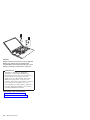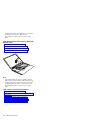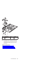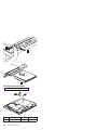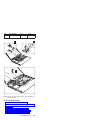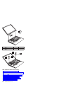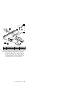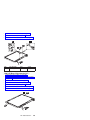
1
ThinkPad R32 Series Hardware Maintenance Manual Before using this information and the product it supports, be sure to read the general information under “Introduction” on page 1, and “Notices” on page 241. First Edition(November 2002) The following paragraph does not apply to the United Kingdom or any country where such provisions are inconsistent with local law: INTERNATIONAL BUSINESS MACHINES CORPORATION PROVIDES THIS PUBLICATION ″AS IS″ WITHOUT ANY WARRANTY OF ANY KIND, EITHER EXPRESS OR IMPLIED, INCLUDING, BUT NOT LIMITED TO, THE LIMITED WARRANTIES OF MERCHANTABILITY OR FITNESS FOR A PARTICULAR PURPOSE. Some states do not allow disclaimers or express or implied warranties in certain transactions; therefore, this statement may not apply to you. This publication could include technical inaccuracies or typographical errors. Changes are periodically made to the information herein; these changes will be incorporated in new editions of the publication. IBM may make improvements or changes in the products or the programs described in this publication at any time. Requests for technical information about IBM products should be made to your IBM Authorized Dealer or your IBM Marketing Representative. © Copyright International Business Machines Corporation 2002. All rights reserved. Note to US Government Users — Documentation related to restricted rights — Use, duplication, or disclosure is subject to restrictions set forth in GSA ADP Schedule Contract with IBM Corp. Preface About this manual This manual contains service and reference information for IBM ThinkPad R32 Series Hardware Maintenance Manual products. Use this manual along with the advanced diagnostic tests to troubleshoot problems effectively. The manual is divided into sections as follows: v The Introduction section provides general information, guidelines, and safety information required to service computers. v The product-specific section includes service, reference, and product-specific parts information. Important This manual is intended for trained servicers who are familiar with ThinkPad products. Use this manual along with the advanced diagnostic tests to troubleshoot problems effectively. Before servicing an IBM ThinkPad product, be sure to review the safety information under “Safety Notices (Multi-lingual Translations)” on page 3,“Safety Information” on page 11 and “Laser Compliance Statement” on page 16 iii iv ThinkPad R32 Series Contents Preface . . . . . . . . . . . . . . . iii ThinkPad R32 Series Hardware Maintenance Manual 1 Introduction . . . . . . . . . . . . . . 1 Important Service Information. . . . . . . . 1 Drive and Diskette Compatibility Matrix . . . . . 2 Safety Notices (Multi-lingual Translations) . . . . 3 Safety Information. . . . . . . . . . . 11 Laser Compliance Statement . . . . . . . 16 General Descriptions . . . . . . . . . . . 19 Read this first . . . . . . . . . . . . . 20 What to do first . . . . . . . . . . . 20 FRU replacement notices . . . . . . . . . 22 LCD replacement notice . . . . . . . . . 22 Screw notices . . . . . . . . . . . . 22 System board/LCD/Inverter replacement notice 23 Related service information . . . . . . . . . 26 Power button as reset switch . . . . . . . 26 Running a low-level format . . . . . . . . 26 Service Web site . . . . . . . . . . . 26 Passwords . . . . . . . . . . . . . 26 Power management features . . . . . . . 28 Fn key combinations . . . . . . . . . . 30 Product recovery program . . . . . . . . 30 Flash BIOS. . . . . . . . . . . . . 33 Checkout guide . . . . . . . . . . . . 34 Testing the computer . . . . . . . . . . 34 Related service information . . . . . . . . 35 Power systems checkout. . . . . . . . . 36 Symptom-to-FRU Index . . . . . . . . . . 39 Numeric Error Codes and Messages . . . . . 39 Beep Symptoms . . . . . . . . . . . 47 LCD-Related Symptoms . . . . . . . . . 49 Keyboard/TrackPoint-Related Symptoms . . . . 50 Indicator-Related Symptoms. . . . . . . . 50 Power-Related Symptoms . . . . . . . . 50 Memory-Related Symptom . . . . . . . . 51 Audio-Related Symptoms . . . . . . . . 51 PC Card (PCMCIA)-Related Symptoms . . . . 51 Power Management-Related Symptoms . . . . 52 Peripheral-Device-Related Symptoms . . . . . 52 Modem-Related Symptom . . . . . . . . 53 Operating System-Related Symptom . . . . . 53 Intermittent Problems . . . . . . . . . . 53 Undetermined Problems . . . . . . . . . 54 ThinkPad R32 Series Part I . . . . . . . . . 55 Product overview . . . . . . . . . . . 56 FRU removals and replacements . . . . . . 62 Locations . . . . . . . . . . . . . 98 Parts list . . . . . . . . . . . . . 101 v ThinkPad R32 Series Part II . . Product overview . . . . FRU removals and replacements Locations . . . . . . . Parts list . . . . . . . ThinkPad R32 Series Part III . . Product overview . . . . FRU removals and replacements Locations . . . . . . . Parts list . . . . . . . Notices . . . . . . . . Trademarks . . . . . . . vi ThinkPad R32 Series . . . . . . . . . . . . . . . . . . . . . . . . . . . . . . . . . . . . . . . . . . . . . . . . . . . . . . . . . . . . . . . . . . . . . . . . 115 116 122 158 161 175 176 182 219 222 241 242 ThinkPad R32 Series Hardware Maintenance Manual Introduction Important Service Information Important Diskette fixes are customer-installable. The diskette fixes are posted on the IBM support site http://www.pc.ibm.com/support/ . Advise customers to contact the PC Company HelpCenter at 800-772-2227 if they need assistance in obtaining or installing any diskette fixes. Customers in Canada should call IBM HelpPC at 800-565-3344 for assistance or download information. FRU Replacement Strategy Before Replacing Parts Ensure that all diskette fixes are installed prior to replacing any FRUs listed in this manual. Use the following strategy to prevent unnecessary FRU replacement and service expense: v If you are instructed to replace a FRU and that does not correct the problem, reinstall the original FRU before you continue. v Some computers have both a processor board and a system board. If you are instructed to replace either the processor board or the system board, and the first board that you replaced does not correct the problem, reinstall the original board, then replace the other (processor or system) board. v If an adapter or device consists of more than one FRU, an error code may be caused by any of the FRUs. Before replacing the adapter or device, remove the FRUs, one by one, to see if the symptoms change. Replace only the FRU that changed the symptoms. Attention: A customized setup configuration (other than default settings) may exist on the computer you are servicing. Running Automatic Configuration may alter those settings. Note the current configuration settings (using the View Configuration option) and verify that the settings are in place when service is complete. 1 Hard Disk Drive Replacement Strategy Always try to run a low-level format before replacing a hard disk drive. Attention: The drive startup sequence in the computer you are servicing might have been changed. Be extremely careful during write operations such as copying, saving, or formatting. Data or programs can be over-written if you select an incorrect drive. How to Use Error Messages Use the error codes displayed on the screen to diagnose failures. If more than one error code is displayed, begin the diagnosis with the first error code. The cause of the first error code can result in false error codes being displayed. If no error code is displayed, see if the error symptom is listed in the Symptom-to-FRU Index for the computer you are servicing. How to Read POST Error Messages POST error messages are displayed on the screen as three, four, five, or eight digits. The error messages that can be displayed as shorter POST messages are highlighted in this index. Some digits will represent different information for SCSI errors versus non-SCSI errors. All SCSI devices are set to a different SCSI ID. Duplicate SCSI ID settings can generate a false error message. Use the SCSI ID to determine whether the error message is coming from an internal or an external device. Drive and Diskette Compatibility Matrix The following table provides identification information for 3.5-inch drives. Diskette Drive Identifying Mark 3.5-Inch - 1.44MB 1.44 on the eject button 3.5-Inch - 2.88MB 2.88 on the eject button The following table provides compatibility information for 3.5-inch diskettes and 3.5-inch diskette drives. Diskette Capacity 1.44MB Drive 2.88MB Drive 1.0MB Read/Write Read/Write 2.0MB Read/Write Read/Write 4.0MB Not Compatible Read/Write 2 ThinkPad R32 Series Safety Notices (Multi-lingual Translations) In this manual, safety notices appear in English with a page number reference to the appropriate multi-lingual, translated safety notice found in this section. The following safety notices are provided in English, French, German, Italian, and Spanish. Safety Notice 1 Before the computer is powered-on after FRU replacement, make sure all screws, springs, or other small parts are in place and are not left loose inside the computer. Verify this by shaking the computer and listening for rattling sounds. Metallic parts or metal flakes can cause electrical shorts. Avant de remettre l’ordinateur sous tension après remplacement d’une unité en clientèle, vérifiez que tous les ressorts, vis et autres pièces sont bien en place et bien fixées. Pour ce faire, secouez l’unité et assurez-vous qu’aucun bruit suspect ne se produit. Des pièces métalliques ou des copeaux de métal pourraient causer un court-circuit. Bevor nach einem FRU-Austausch der Computer wieder angeschlossen wird, muβ sichergestellt werden, daβ keine Schrauben, Federn oder andere Kleinteile fehlen oder im Gehäuse vergessen wurden. Der Computer muβ geschüttelt und auf Klappergeräusche geprüft werden. Metallteile oder -splitter können Kurzschlüsse erzeugen. Prima di accendere l’elaboratore dopo che é stata effettuata la sostituzione di una FRU, accertarsi che tutte le viti, le molle e tutte le altri parti di piccole dimensioni siano nella corretta posizione e non siano sparse all’interno dell’elaboratore. Verificare ciò scuotendo l’elaboratore e prestando attenzione ad eventuali rumori; eventuali parti o pezzetti metallici possono provocare cortocircuiti pericolosi. Antes de encender el sistema despues de sustituir una FRU, compruebe que todos los tornillos, muelles y demás piezas pequeñas se encuentran en su sitio y no se encuentran sueltas dentro del sistema. Compruébelo agitando el sistema y escuchando los posibles ruidos que provocarían. Las piezas metálicas pueden causar cortocircuitos eléctricos. MT 2658/2659/2677 3 Safety Notice 2 Some standby batteries contain a small amount of nickel and cadmium. Do not disassemble it, recharge it, throw it into fire or water, or short-circuit it. Dispose of the battery as required by local ordinances or regulations. Use only the battery in the appropriate parts listing. Use of an incorrect battery can result in ignition or explosion of the battery. Certaines batteries de secours contiennent du nickel et du cadmium. Ne les démontez pas, ne les rechargez pas, ne les exposez ni au feu ni à l’eau. Ne les mettez pas en court-circuit. Pour les mettre au rebut, conformez-vous à la réglementation en vigueur. Lorsque vous remplacez la pile de sauvegarde ou celle de l’horloge temps réel, veillez à n’utiliser que les modèles cités dans la liste de pièces détachées adéquate. Une batterie ou une pile inappropriée risque de prendre feu ou d’exploser. Die Bereitschaftsbatterie, die sich unter dem Diskettenlaufwerk befindet, kann geringe Mengen Nickel und Cadmium enthalten. Sie darf nur durch die Verkaufsstelle oder den IBM Kundendienst ausgetauscht werden. Sie darf nicht zerlegt, wiederaufgeladen, kurzgeschlossen, oder Feuer oder Wasser ausgesetzt werden. Die Batterie kann schwere Verbrennungen oder Verätzungen verursachen. Bei der Entsorgung die örtlichen Bestimmungen für Sondermüll beachten. Beim Ersetzen der Bereitschafts- oder Systembatterie nur Batterien des Typs verwenden, der in der Ersatzteilliste aufgeführt ist. Der Einsatz falscher Batterien kann zu Entzündung oder Explosion führen. 4 ThinkPad R32 Series (Continued) Alcune batterie di riserva contengono una piccola quantità di nichel e cadmio. Non smontarle, ricaricarle, gettarle nel fuoco o nell’acqua né cortocircuitarle. Smaltirle secondo la normativa in vigore (DPR 915/82, successive disposizioni e disposizioni locali). Quando si sostituisce la batteria dell’RTC (real time clock) o la batteria di supporto, utilizzare soltanto i tipi inseriti nell’appropriato Catalogo parti. L’impiego di una batteria non adatta potrebbe determinare l’incendio o l’esplosione della batteria stessa. Algunas baterías de reserva contienen una pequeña cantidad de níquel y cadmio. No las desmonte, ni recargue, ni las eche al fuego o al agua ni las cortocircuite. Deséchelas tal como dispone la normativa local. Utilice sólo baterías que se encuentren en la lista de piezas. La utilización de una batería no apropiada puede provocar la ignición o explosión de la misma. MT 2658/2659/2677 5 Safety Notice 3 The battery pack contains small amounts of nickel. Do not disassemble it, throw it into fire or water, or short-circuit it. Dispose of the battery pack as required by local ordinances or regulations. Use only the battery in the appropriate parts listing when replacing the battery pack. Use of an incorrect battery can result in ignition or explosion of the battery. La batterie contient du nickel. Ne la démontez pas, ne l’exposez ni au feu ni à l’eau. Ne la mettez pas en court-circuit. Pour la mettre au rebut, conformez-vous à la réglementation en vigueur. Lorsque vous remplacez la batterie, veillez à n’utiliser que les modèles cités dans la liste de pièces détachées adéquate. En effet, une batterie inappropriée risque de prendre feu ou d’exploser. Akkus enthalten geringe Mengen von Nickel. Sie dürfen nicht zerlegt, wiederaufgeladen, kurzgeschlossen, oder Feuer oder Wasser ausgesetzt werden. Bei der Entsorgung die örtlichen Bestimmungen für Sondermüll beachten. Beim Ersetzen der Batterie nur Batterien des Typs verwenden, der in der Ersatzteilliste aufgeführt ist. Der Einsatz falscher Batterien kann zu Entzündung oder Explosion führen. La batteria contiene piccole quantità di nichel. Non smontarla, gettarla nel fuoco o nell’acqua né cortocircuitarla. Smaltirla secondo la normativa in vigore (DPR 915/82, successive disposizioni e disposizioni locali). Quando si sostituisce la batteria, utilizzare soltanto i tipi inseriti nell’appropriato Catalogo parti. L’impiego di una batteria non adatta potrebbe determinare l’incendio o l’esplosione della batteria stessa. Las baterías contienen pequeñas cantidades de níquel. No las desmonte, ni recargue, ni las eche al fuego o al agua ni las cortocircuite. Deséchelas tal como dispone la normativa local. Utilice sólo baterías que se encuentren en la lista de piezas al sustituir la batería. La utilización de una batería no apropiada puede provocar la ignición o explosión de la misma. 6 ThinkPad R32 Series Safety Notice 4 The lithium battery can cause a fire, explosion, or severe burn. Do not recharge it, remove its polarized connector, disassemble it, heat it above 100°C (212°F), incinerate it, or expose its cell contents to water. Dispose of the battery as required by local ordinances or regulations. Use only the battery in the appropriate parts listing. Use of an incorrect battery can result in ignition or explosion of the battery. La pile de sauvegarde contient du lithium. Elle présente des risques d’incendie, d’explosion ou de brûlures graves. Ne la rechargez pas, ne retirez pas son connecteur polarisé et ne la démontez pas. Ne l’exposez pas à une temperature supérieure à 100°C, ne la faites pas brûler et n’en exposez pas le contenu à l’eau. Mettez la pile au rebut conformément à la réglementation en vigueur. Une pile inappropriée risque de prendre feu ou d’exploser. Die Systembatterie ist eine Lithiumbatterie. Sie kann sich entzünden, explodieren oder schwere Verbrennungen hervorrufen. Batterien dieses Typs dürfen nicht aufgeladen, zerlegt, über 100 C erhitzt oder verbrannt werden. Auch darf ihr Inhalt nicht mit Wasser in Verbindung gebracht oder der zur richtigen Polung angebrachte Verbindungsstecker entfernt werden. Bei der Entsorgung die örtlichen Bestimmungen für Sondermüll beachten. Beim Ersetzen der Batterie nur Batterien des Typs verwenden, der in der Ersatzteilliste aufgeführt ist. Der Einsatz falscher Batterien kann zu Entzündung oder Explosion führen. La batteria di supporto e una batteria al litio e puo incendiarsi, esplodere o procurare gravi ustioni. Evitare di ricaricarla, smontarne il connettore polarizzato, smontarla, riscaldarla ad una temperatura superiore ai 100 gradi centigradi, incendiarla o gettarla in acqua. Smaltirla secondo la normativa in vigore (DPR 915/82, successive disposizioni e disposizioni locali). L’impiego di una batteria non adatta potrebbe determinare l’incendio o l’esplosione della batteria stessa. MT 2658/2659/2677 7 (Continued) La bateria de repuesto es una bateria de litio y puede provocar incendios, explosiones o quemaduras graves. No la recargue, ni quite el conector polarizado, ni la desmonte, ni caliente por encima de los 100°C (212°F), ni la incinere ni exponga el contenido de sus celdas al agua. Deséchela tal como dispone la normativa local. 8 ThinkPad R32 Series Safety Notice 5 If the LCD breaks and the fluid from inside the LCD gets into your eyes or on your hands, immediately wash the affected areas with water for at least 15 minutes. Seek medical care if any symptoms from the fluid are present after washing. Si le panneau d’affichage à cristaux liquides se brise et que vous recevez dans les yeux ou sur les mains une partie du fluide, rincez-les abondamment pendant au moins quinze minutes. Consultez un médecin si des symptômes persistent après le lavage. Die Leuchtstoffröhre im LCD-Bildschirm enthält Quecksilber. Bei der Entsorgung die örtlichen Bestimmungen für Sondermüll beachten. Der LCD-Bildschirm besteht aus Glas und kann zerbrechen, wenn er unsachgemäβ behandelt wird oder der Computer auf den Boden fällt. Wenn der Bildschirm beschädigt ist und die darin befindliche Flüssigkeit in Kontakt mit Haut und Augen gerät, sollten die betroffenen Stellen mindestens 15 Minuten mit Wasser abgespült und bei Beschwerden anschlieβend ein Arzt aufgesucht werden. Nel caso che caso l’LCD si dovesse rompere ed il liquido in esso contenuto entrasse in contatto con gli occhi o le mani, lavare immediatamente le parti interessate con acqua corrente per almeno 15 minuti; poi consultare un medico se i sintomi dovessero permanere. Si la LCD se rompe y el fluido de su interior entra en contacto con sus ojos o sus manos, lave inmediatamente las áreas afectadas con agua durante 15 minutos como mínimo. Obtenga atención medica si se presenta algún síntoma del fluido despues de lavarse. MT 2658/2659/2677 9 Safety Notice 6 To avoid shock, do not remove the plastic cover that surrounds the lower portion of the inverter card. Afin d’éviter tout risque de choc électrique, ne retirez pas le cache en plastique protégeant la partie inférieure de la carte d’alimentation. Aus Sicherheitsgründen die Kunststoffabdeckung, die den unteren Teil der Spannungswandlerplatine umgibt, nicht entfernen. Per evitare scosse elettriche, non rimuovere la copertura in plastica che avvolge la parte inferiore della scheda invertitore. Para evitar descargas, no quite la cubierta de plástico que rodea la parte baja de la tarjeta invertida. Safety Notice 7 Though main batteries have low voltage, a shorted or grounded battery can produce enough current to burn combustible materials or personnel. Bien que le voltage des batteries principales soit peu élevé, le court-circuit ou la mise à la masse d’une batterie peut produire suffisamment de courant pour brûler des matériaux combustibles ou causer des brûlures corporelles graves. Obwohl Hauptbatterien eine niedrige Spannung haben, können sie doch bei Kurzschluβ oder Erdung genug Strom abgeben, um brennbare Materialien zu entzünden oder Verletzungen bei Personen hervorzurufen. Sebbene le batterie di alimentazione siano a basso voltaggio, una batteria in corto circuito o a massa può fornire corrente sufficiente da bruciare materiali combustibili o provocare ustioni ai tecnici di manutenzione. Aunque las baterías principales tienen un voltaje bajo, una batería cortocircuitada o con contacto a tierra puede producir la corriente suficiente como para quemar material combustible o provocar quemaduras en el personal. 10 ThinkPad R32 Series Safety Notice 8 Before removing any FRU, power-off the computer, unplug all power cords from electrical outlets, remove the battery pack, then disconnect any interconnecting cables. Avant de retirer une unité remplaçable en clientèle, mettez le système hors tension, débranchez tous les cordons d’alimentation des socles de prise de courant, retirez la batterie et déconnectez tous les cordons d’interface. Die Stromzufuhr muβ abgeschaltet, alle Stromkabel aus der Steckdose gezogen, der Akku entfernt und alle Verbindungskabel abgenommen sein, bevor eine FRU entfernt wird. Prima di rimuovere qualsiasi FRU, spegnere il sistema, scollegare dalle prese elettriche tutti i cavi di alimentazione, rimuovere la batteria e poi scollegare i cavi di interconnessione. Antes de quitar una FRU, apague el sistema, desenchufe todos los cables de las tomas de corriente eléctrica, quite la batería y, a continuación, desconecte cualquier cable de conexión entre dispositivos. Safety Information The following section contains the safety information that you need to be familiar with before servicing an IBM mobile computer. General Safety Follow these rules to ensure general safety: v Observe good housekeeping in the area of the machines during and after maintenance. v When lifting any heavy object: 1. Ensure you can stand safety without slipping. 2. Distribute the weight of the object equally between your feet. 3. Use a slow lifting force. Never move suddenly or twist when you attempt to lift. 4. Lift by standing or by pushing up with your leg muscles; this action removes the strain from the muscles in your back. Do not attempt to lift any objects that weigh more than 16 kg (35 lb) or objects that you think are too heavy for you. MT 2658/2659/2677 11 v Do not perform any action that causes hazards to the customer, or that makes the equipment unsafe. v Before you start the machine, ensure that other service representatives and the customer’s personnel are not in a hazardous position. v Place removed covers and other parts in a safe place, away from all personnel, while you are servicing the machine. v Keep your tool case away from walk areas so that other people will not trip over it. v Do not wear loose clothing that can be trapped in the moving parts of a machine. Ensure that your sleeves are fastened or rolled up above your elbows. If your hair is long, fasten it. v Insert the ends of your necktie or scarf inside clothing or fasten it with a nonconductive clip, approximately 8 centimeters (3 inches) from the end. v Do not wear jewelry, chains, metal-frame eyeglasses, or metal fasteners for your clothing. Attention: Metal objects are good electrical conductors. v Wear safety glasses when you are: hammering, drilling soldering, cutting wire, attaching springs, using solvents, or working in any other conditions that might be hazardous to your eyes. v After service, reinstall all safety shields, guards, labels, and ground wires. Replace any safety device that is worn or defective. v Reinstall all covers correctly before returning the machine to the customer. Electrical Safety Observe the following rules when working on electrical equipment. Important Use only approved tools and test equipment. Some hand tools have handles covered with a soft material that does not insulate you when working with live electrical currents. Many customers have, near their equipment, rubber floor mats that contain small conductive fibers to decrease electrostatic discharges. Do not use this type of mat to protect yourself from electrical shock. v Find the room emergency power-off (EPO) switch, disconnecting switch, or electrical outlet. If an electrical accident occurs, you can then operate the switch or unplug the power cord quickly. 12 ThinkPad R32 Series v Do not work alone under hazardous conditions or near equipment that has hazardous voltages. v Disconnect all power before: – Performing a mechanical inspection – Working near power supplies – Removing or installing main units v Before you start to work on the machine, unplug the power cord. If you cannot unplug it, ask the customer to power-off the wall box that supplies power to the machine and to lock the wall box in the off position. v If you need to work on a machine that has exposed electrical circuits, observe the following precautions: – Ensure that another person, familiar with the power-off controls, is near you. Attention: Another person must be there to switch off the power, if necessary. – Use only one hand when working with powered-on electrical equipment; keep the other hand in your pocket or behind your back. Attention: There must be a complete circuit to cause electrical shock. By observing the above rule, you may prevent a current from passing through your body. – When using testers, set the controls correctly and use the approved probe leads and accessories for that tester. – Stand on suitable rubber mats (obtained locally, if necessary) to insulate you from grounds such as metal floor strips and machine frames. Observe the special safety precautions when you work with very high voltages; these instructions are in the safety sections of maintenance information. Use extreme care when measuring high voltages. v Regularly inspect and maintain your electrical hand tools for safe operational condition. v Do not use worn or broken tools and testers. v Never assume that power has been disconnected from a circuit. First, check that it has been powered-off. v Always look carefully for possible hazards in your work area. Examples of these hazards are moist floors, nongrounded power extension cables, power surges, and missing safety grounds. v Do not touch live electrical circuits with the reflective surface of a plastic dental mirror. The surface is conductive; such touching can cause personal injury and machine damage. MT 2658/2659/2677 13 v Do not service the following parts with the power on when they are removed from their normal operating places in a machine: – Power supply units – Pumps – Blowers and fans – Motor generators and similar units. (This practice ensures correct grounding of the units.) v If an electrical accident occurs: – Use caution; do not become a victim yourself. – Switch off power. – Send another person to get medical aid. Safety Inspection Guide The intent of this inspection guide is to assist you in identifying potentially unsafe conditions on these products. Each machine, as it was designed and built, had required safety items installed to protect users and service personnel from injury. This guide addresses only those items. However, good judgment should be used to identify potential safety hazards due to attachment of non-IBM features or options not covered by this inspection guide. If any unsafe conditions are present, you must determine how serious the apparent hazard could be and whether you can continue without first correcting the problem. Consider these conditions and the safety hazards they present: v Electrical hazards, especially primary power (primary voltage on the frame can cause serious or fatal electrical shock). v Explosive hazards, such as a damaged CRT face or bulging capacitor. v Mechanical hazards, such as loose or missing hardware. The guide consists of a series of steps presented in a checklist. Begin the checks with the power off, and the power cord disconnected. Checklist: 1. Check exterior covers for damage (loose, broken, or sharp edges). 2. Power-off the computer. Disconnect the power cord. 3. Check the power cord for: a. A third-wire ground connector in good condition. Use a meter to measure third-wire ground 14 ThinkPad R32 Series continuity for 0.1 ohm or less between the external ground pin and frame ground. b. The power cord should be the appropriate type as specified in the parts listings. c. Insulation must not be frayed or worn. 4. Remove the cover. 5. Check for any obvious non-IBM alterations. Use good judgment as to the safety of any non-IBM alterations. 6. Check inside the unit for any obvious unsafe conditions, such as metal filings, contamination, water or other liquids, or signs of fire or smoke damage. 7. Check for worn, frayed, or pinched cables. 8. Check that the power-supply cover fasteners (screws or rivets) have not been removed or tampered with. Handling Electrostatic Discharge-Sensitive Devices Any computer part containing transistors or integrated circuits ( ICs) should be considered sensitive to electrostatic discharge (ESD). ESD damage can occur when there is a difference in charge between objects. Protect against ESD damage by equalizing the charge so that the machine, the part, the work mat, and the person handling the part are all at the same charge. Notes: 1. Use product-specific ESD procedures when they exceed the requirements noted here. 2. Make sure that the ESD protective devices you use have been certified (ISO 9000) as fully effective. When handling ESD-sensitive parts: v Keep the parts in protective packages until they are inserted into the product. v Avoid contact with other people. v Wear a grounded wrist strap against your skin to eliminate static on your body. v Prevent the part from touching your clothing. Most clothing is insulative and retains a charge even when you are wearing a wrist strap. v Use the black side of a grounded work mat to provide a static-free work surface. The mat is especially useful when handling ESD-sensitive devices. v Select a grounding system, such as those listed below, to provide protection that meets the specific service requirement. Note: The use of a grounding system is desirable but not required to protect against ESD damage. MT 2658/2659/2677 15 – Attach the ESD ground clip to any frame ground, ground braid, or green-wire ground. – Use an ESD common ground or reference point when working on a double-insulated or battery-operated system. – You can use coax or connector-outside shells on these systems. – Use the round ground-prong of the AC plug on AC-operated computers. Grounding Requirements Electrical grounding of the computer is required for operator safety and correct system function. Proper grounding of the electrical outlet can be verified by a certified electrician. Laser Compliance Statement Some IBM Personal Computer models are equipped from the factory with a CD-ROM drive. CD-ROM drives are also sold separately as options. The CD-ROM drive is a laser product. The CD-ROM drive is certified in the U.S. to conform to the requirements of the Department of Health and Human Services 21 Code of Federal Regulations (DHHS 21 CFR) Subchapter J for Class 1 laser products. Elsewhere, the drive is certified to conform to the requirements of the International Electrotechnical Commission (IEC) 825 and CENELEC EN 60 825 for Class 1 laser products. When a CD-ROM drive is installed, note the following. 16 ThinkPad R32 Series CAUTION: Use of controls or adjustments or performance of procedures other than those specified herein might result in hazardous radiation exposure. O uso de controles, ajustes ou desempenho de procedimentos diferentes daqueles aqui especificados pode resultar em perigosa exposição à radiação. Pour éviter tout risque d’exposition au rayon laser, respectez les consignes de réglage et d’utilisation des commandes, ainsi que les procédures décrites. Werden Steuer- und Einstellelemente anders als hier festgesetzt verwendet, kann gefährliche Laserstrahlung auftreten. L’utilizzo di controlli, regolazioni o l’esecuzione di procedure diverse da quelle specificate possono provocare l’esposizione a El uso de controles o ajustes o la ejecución de procedimientos distintos de los aquí especificados puede provocar la exposición a radiaciones peligrosas. Opening the CD-ROM drive could result in exposure to hazardous laser radiation. There are no serviceable parts inside the CD-ROM drive. Do not open. Some CD-ROM drives contain an embedded Class 3A or Class 3B laser diode. Note the following. MT 2658/2659/2677 17 DANGER Laser radiation when open. Do not stare into the beam, do not view directly with optical instruments, and avoid direct exposure to the beam. Radiação por raio laser ao abrir. Não olhe fixo no feixe de luz, não olhe diretamente por meio de instrumentos óticos e evite exposição direta com o feixe de luz. Rayonnement laser si carter ouvert. Évitez de fixer le faisceau, de le regarder directement avec des instruments optiques, ou de vous exposer au rayon. Laserstrahlung bei geöffnetem Gerät. Nicht direkt oder über optische Instrumente in den Laserstrahl sehen und den Strahlungsbereich meiden. Kinyitáskor lézersugár ! Ne nézzen bele se szabad szemmel, se optikai eszközökkel. Kerülje a sugárnyalábbal való érintkezést ! Aprendo l’unità vengono emesse radiazioni laser. Non fissare il fascio, non guardarlo direttamente con strumenti ottici e evitare l’esposizione diretta al fascio. Radiación láser al abrir. No mire fijamente ni examine con instrumental óptico el haz de luz. Evite la exposición directa al haz. 18 ThinkPad R32 Series General Descriptions This chapter includes descriptions for any ThinkPad model that has the PC-Doctor DOS diagnostics program. Some descriptions might not apply to your particular computer. MT 2658/2659/2677 19 Read this first Before you go to the checkout guide, be sure to read this section. Important Notes: v Only certified trained personnel should service the computer. v Read the entire FRU service procedures before replacing any FRUs. v Use new nylon-coated screws when you replace FRUs. v Be extremely careful during write operations such as copying, saving, or formatting. Drives in the computer that you are servicing might have been rearranged or the drive startup sequence might have been altered. If you select an incorrect drive, data or programs could be overwritten. v Replace FRUs only for the correct model. When you replace a FRU, make sure that the model of the machine and FRU part number are correct by referring to the FRU parts list. v A FRU should not be replaced because of a single, unreproducible failure. Single failure can occur for a variety of reasons that have nothing to do with a hardware defect, such as: cosmic radiation, electrostatic discharge, or software error. FRU replacement should be considered only when a recurring problem exists. In this case, clear the error log and run the test again. Do not replace FRUs if log errors do not reappear. v Be careful not to replace a non-defective FRU. What to do first The servicer must include the following in the parts exchange form or parts return form that is attached to the returned FRU: 1. Name and phone number of servicer 2. Date of service 3. Date when part failed 4. Date of purchase 5. Failure symptoms, error codes appearing on display, and beep symptoms 6. Procedure index and page number in which failing FRU was detected 7. Failing FRU name and part number 8. Machine type, model number and serial number 9. Customer’s name and address 20 ThinkPad R32 Series Before checking problems with the computer, determine whether the damage is covered under the warranty by referring to the following: Note for Warranty: For Warranty: During the warranty period, the customer may be responsible for repair costs if the computer damage was caused by misuse, accident, modification, unsuitable physical or operating environment, or improper maintenance by the customer. The following list provides some common items that are not covered under warranty and some symptoms that may indicate the system was subjected to stresses beyond normal use. The following is not covered under warranty: v LCD panel cracked by applying excessive force or by being dropped. v Scratched (cosmetic) parts. v Cracked or broken plastic parts, broken latches, broken pins, or broken connectors caused by excessive force. v Damage caused by liquid spilled into the system. v Damage caused by improperly inserting a PC Card or installation of an incompatible card. v Damage caused by foreign material in the FDD. v Diskette drive damage caused by pressing the diskette drive cover or inserting diskettes with multiple labels. v Damaged or bent diskette drive eject button. v CD-ROM/DVD-ROM drive damage caused by excessive force, shock, or by being dropped. v Fuses blown by attaching a nonsupported device. v Forgotten computer password (making the computer unusable). The following symptoms might indicate damage caused by non-warranted activities: v Missing parts may be a symptom of unauthorized service or modification. v HDD spindles can become noisy if subjected to excessive force or by being dropped. v I9990303 errors can be caused by exposure to strong magnetic fields. MT 2658/2659/2677 21 FRU replacement notices This section contains notices for removal and replacement. Read this section carefully before replacing any FRU. LCD replacement notice The TFT LCD for the computer contains many thin-film transistors (TFTs). A small number of missing, discolored, or lighted dots (on all the time) is characteristic of TFT LCD technology, but excessive pixel problems can cause viewing concerns. The LCD should be replaced if the number of missing, discolored, or lighted dots in any background is: v XGA : 8 or more bright dots, 8 or more dark dots, or a total of 9 or more bright and dark dots. Screw notices This computer uses special nylon-coated screws with the following characteristics: v They maintain tight connections. v They do not easily come loose, even with shock or vibration. v They need additional force to tighten. v They should be used only once. Do the following when you service this machine: v Keep the screw kit (P/N 08K6560) in your tool bag. v Always use new screws if you are instructed. v Use a torque screwdriver if you have one. Loose screws can cause a reliability problem. The IBM ThinkPad computer addresses this problem with nylon-coated screws. Tighten screws as follows: v Plastic to plastic Turn an additional 90 degrees after the screw head touches the surface of the plastic part: v Logic card to plastic 22 ThinkPad R32 Series Turn an additional 180 degrees after the screw head touches the surface of the plastic part: v Torque driver If you have a torque driver, refer to the ″Torque″ column with each step. v Make sure you use the correct screw, and tighten all screws firmly to the torque shown in the table if you have a torque screwdriver. Never use a screw that you removed. Use a new one. Make sure the screws are tightened firmly. System board/LCD/Inverter replacement notice Restoring the LCD panel ID The EEPROM on the inverter stores its supported LCD type ID code. If you replace a LCD with one of a different brand or use a new inverter, the ID information in the inverter EEPROM should be updated. Follow the steps blew to set the LCD panel ID: 1. Install the ThinkPad Maintenance Diskette and restart the computer. 2. When the IBM logo is displayed, press the ″ESC″ key few times until BIOS copyright and diagnostics screen appears. 3. Select 1. LCD Panel ID Utility from the main menu. 4. Follow the instruction on screen to read current or to set new LCD Panel ID code. 5. Restart computer : the new LCD should work normally. Note: When you set a new LCD Panel ID and the new LCD is not yet enabled (to function), so connect an external CRT to see the program execution process. MT 2658/2659/2677 23 CAUTION: Make sure the new ID code you choose corresponds with the LCD brand and type. If you write a wrong ID into inverterm, just reboot and re-execute the program and input the correct ID code. Note: If LCD cannot display after change ID code, make sure you write the correct ID code, or try reseating the LCD coaxtial cable connectors. Thermal Sensor The system is equipped with sensors to protect against system overheating. By setting system and processor thermal thresholds, the system can turn on the cooling fan or shut down automatically when temperatures reach the defined threshold parameters. System experiencing frequent auto sensor shutdown may need to reset the thermal sensor threshold and execute the fan test to ensure the normal operation of the cooling fan. Follow the steps below to set thermal threshold: 1. Install the ThinkPad Maintenance Diskette and restart the computer. 2. When the IBM logo is displayed, press the ″ESC″ key few times until BIOS copyright and diagnostics screen appears. 3. Select 2. Thermal Sensor Utility from the main menu. 4. Select 1. Read Thermal Settingto view the original setting or 2. Set Default Thermal Settingto restore the default setting. Serial number of the system unit When the computer was manufactured, the EEPROM on the system board was loaded with the serial numbers of the system and all major components. These numbers need to remain the same throughout the life of the computer. If you replace the system board, you must restore the serial number of the system unit to its original value. Before replacing the system board, save the original serial number by doing the following: 1. Install the Maintenance Diskette and restart the computer. 2. When the IBM logo is displayed, press the ″ESC″ key few times until BIOS copyright and diagnostics screen appears. 3. Select 2.VPD Utility from the main menu. 24 ThinkPad R32 Series 4. Follow the instruction on the screen to read original system serial number. After you have replaced the system board, restore the serial number by doing the following: 1. Install the Maintenance Diskette and restart the computer. 2. When the IBM logo is displayed, press the ″ESC″ key few times until BIOS copyright and diagnostics screen appears. 3. Select 2.VPD Utility from the main menu. 4. Follow the instruction on the screen to update the system serial number. Note: The serial number of the system unit is written on the label attached on the bottom of the computer. UUID The Universal Unique Identifier (UUID) is a 128–bit number uniquely assigned to your computer at production and stored in the EEPROM of your 24RF08. The algorithm that generates the unique number is designed to provide unique IDs until the year A.D. 3400. Consequently, no tow computers in the world will have the same number. When you replace the system board, you must set the UUID on the new system board as follows: 1. Install the ThinkPad Maintenance Diskette and restart the computer. 2. When the IBM logo is displayed, press the ″ESC″ key few times until BIOS copyright and diagnostics screen appears. 3. Select 3. UUID Data Utility from the main menu then make a selection to read or create the UUID data. A new UUID is created and written. If a valid UUID already exists, it is not overwritten. MT 2658/2659/2677 25 Related service information This section provides information about the following: v “Power button as reset switch” v “Running a low-level format” v “Service Web site” v “Passwords” v “Power management features” on page 28 v “Fn key combinations” on page 30 v “Product recovery program” on page 30 v “Flash BIOS” on page 33 Power button as reset switch The power button acts as a reset switch when pressed for more than 4 seconds. This resets the system (regardless of the microcode status) and forces the power off. Use this only when power is not completely off or the microcode is in a hung state. Running a low-level format Attention: Make sure the drive address to be formatted is correct. This procedure erases all information on the disk. To format the hard disk, select Utility, and then use the Full Erase Hard Drive or Quick Erase Hard Drive in Utility of the PC-Doctor for DOS program. Refer to “Testing the computer” on page 34. Service Web site When the latest maintenance diskette and system program service diskette are available, they are posted on: Maintenance diskette: http://www.pc.ibm.com/partner/infotips System program service diskette: http://www.pc.ibm.com/us/files.html or http://www.pc.ibm.com/qtechinfo/TPAD-MATRIX.html Passwords When the power-on password (POP), hard disk password (HDP), and supervisor password (SVP) are used, the following situations may occur: v If the POP is the same as the HDP, the POP prompt appears, but the HDP prompt does not appear. v If the POP is not the same as the HDP, both prompts appear. 26 ThinkPad R32 Series v When SVP is set, POST should invoke BIOS setup without erasing POP. Before entering BIOS setup SVP will be prompted. If correct SVP is entered, POST enters BIOS setup without erasing POP. To boot up the system user should override POP by SVP at the password sub-menu. v When SVP is not set, POST erase the POP and then boots up the system. Power-on passwords Power-on password is a security feature that is used to protect the system from unauthorized access. If power-on is forgotten, follow the procedure described in ″ Removing the Power-on password″. Supervisor password A supervisor password (SVP) protects the system information stored in the IBM BIOS Setup Utility . The SVP must be entered in order to access the IBM BIOS Setup Utility and make changes to system configuration settings. Attention: If the SVP has been forgotten and cannot be made available to the servicer, there is no service procedure to reset the password. The system board must be replaced for a scheduled fee. Removing the power-on password If the customer forgets the power-on password, follow this procedure to erase POP if SVP is not set: 1. Turn off the system. 2. Set DIP SW2, Bit 2 to ON. 3. Turn on the system, and confirm the system starts without prompting for Power-on password. 4. Turn off the system. 5. Set DIP SW2, Bit 2 to OFF. If SVP is set, do the followings to erase POP: 1. Power on the computer and press F1 to enter the BIOS Utility menu. 2. Enter correct SVP (Supervisor password) at the password prompt. MT 2658/2659/2677 27 3. The main screen displays as below: 4. Using the up or down arrow key, select Password. 5. Press the Enter key. The following submenu is displayed: * Power-On password * Supervisor password * Lock BIOS setting * Hard disk x password 6. Select Power-On password and press Enter . 7. Type in correct SVP at ″Enter Current Password″ and press Enter. 8. PressEnter at ″Enter New Password″. 9. Press Enter at ″Confirm New Password″. 10. Press Enter in the Changes have been saved window. 11. Press F10; then select Yes in the Setup confirmation window. Refer to “Switch Locations” on page 100 Hard disk password The hard disk password is a security feature that is used to protect the hard disk data from unauthorized access. Attention: If the hard disk password is forgotten, IBM does not provide any services to reset the hard drive password nor recover data from the hard drive. The hard drive can be replaced for a scheduled fee. Power management features Power management modes are available in the computer system to reduce power consumption and to prolong battery life. 28 ThinkPad R32 Series Suspend mode When in standby mode, the following occurs: v The LCD backlight turns off. v The hard disk motor either spins down or stops (controlled by OS). v Suspend LED turns on. Events that cause the computer to enter standby mode: Note: These events depend on the Power button, Sleep button and Lid settings (options set to standby mode) in the ″Advanced″ page of the ″Power Management Properties″ screen. v Standby requested by the Sleep button (Fn+F4) v Standby requested by the power button v Standby requested by closing the lid. Events that cause the computer to exit standby mode: v RTC alarm v Power-on switch is operated v Fn key is pressed v The LCD is opened (if the system entered standby mode from closing the lid). Note: This is true if When I close the lid of my portable computer: is set to Standby in the ″Advanced″ page of the ″Power Management Properties″ screen. v An embedded modem signals the modem ring indicator v The battery power is at a critical level. Display off mode When in display off mode, the following occur: v The LCD backlight turns off. Events that cause the computer to enter display off mode: v Hotkey : Fn+F3 Events that cause the computer to exit display off mode: v Anykey or mouse operation Hibernation mode When in hibernation mode, the following occurs: v The system status, RAM, VRAM, and setup data are stored on the hard disk. v The system is powered off. Events that cause the computer to enter hibernation mode: MT 2658/2659/2677 29 Note: These events depend on the Power button, Sleep button and Lid settings (options set to hibernate mode) in the ″Advanced″ page of the ″Power Management Properties″ screen. v Hibernation requested by the Sleep button (Fn+F4) or (Fn+F12) v Hibernation requested by the power button v Hibernation requested by closing the lid. Events that cause the computer to exit hibernation mode: v RTC alarm v Power-on switch is operated v WOL (wake on Lan) When power is turned on, the hibernation history in the boot record on the hard disk is recognized and the system status is restored from the hard disk to resume operation. Fn key combinations The following table shows the Fn key and function key combinations and their corresponding functions. Some of the keys do not work if proper device drivers and utilities are not installed. Fn key Function Fn+F3 Display off Fn+F4 Sleep button Fn+F7 Switch display output location. Fn+F8 Display expansion Fn+F12 Hibernation Fn+PageUp Thinkpad light Fn+Home Brightness up Fn+End Brightness down Product recovery program Restoring the Pre-installed Software To restore the pre-installed software, you can use either the Product Recovery program or a Recovery CD. The Product Recovery program is in a section of the hard disk drive (the Service Partition) that is not displayed by Windows Explorer. Use the Recovery CD if it was provided with the computer. Note: The recovery process might take up to 2 hours. To use the Product Recovery program to restore the pre-installed software, do the following: 30 ThinkPad R32 Series 1. Save all files and shut down the desktop. 2. Turn off the computer. 3. Turn on the computer. Quickly press F11 when this message is displayed on the screen: ...″To start the Product Recovery program, press F11″ .....This message is displayed for only a few seconds. Note: If this message does not appear, you can use a Recovery Repair diskette to get access to the Product Recovery program.(see“Creating a Recovery Repair diskette” on page 32 for instructions for making the Recovery Repair diskette) 4. From the list displayed on the screen, select the operating system you want to recover. 5. Select the recovery options you want, and follow the instructions on the screen. Creating the Service Partition To create Service Partition and install the preloaded system from Recovery CD, do the following; To create Service Partition [SP]: 1. Erase all partitions on the hard-disk drive using FDISK or similar application. 2. Boot with Recovery CD (and boot diskette if required). 3. A menu will appear stating ″Your computer originally included a Product Recovery program ... Reinstall the Product Recovery Program? (Y/N) [ ]″.}. Note: If the hard-disk drive contains any partitions, you will not receive this menu - go to step 1. 4. Enter ″Y″ and Service Partition will be created and loaded with D2D files. Note: If you do not want to create Service Partition, press ″N″ , and the d then go to step 8. 5. Press ″Enter″ at next window to continue. * Service Partition will be created. System will automatically reboot during this process. * Recovery process will copy some files to the Service Partition, PKUNZIP others * Follow prompts - you may be prompted to change CDs. * System will reboot when complete, continue to step 6 to install preloaded system. Install preloaded system from CD: 6. Boot with Recovery CD (and boot diskette if required) MT 2658/2659/2677 31 7. If the hard-disk drive is blank, a menu will appear stating ″Your computer originally included a Product Recovery program ... Reinstall the Product Recovery Program? (Y/N) [ ]″. * To install Service Partition, go to step 4. * To preload hard-disk drive without installing Service Partition, press ″N″. 8. If a menu appears asking which operating system to install, highlight proper operating system and press ″″ENTER″. 9. A menu will appear stating ″Full Recovery:″. Press ″″ENTER″ to select. 10. Enter ″Y″ at the three windows which follow. 11. Follow prompts to complete Recovery. Creating a Recovery Repair diskette The Recovery Repair diskette is used to recover the prompt that is needed to access the Product Recovery program, if the prompt does not appear. Make a Recovery Repair diskette and save it for future use. To make a Recovery Repair diskette: 1. Shut down and turn off the computer. 2. Attach the external diskette drive to the computer. 3. At the prompt, pressF11. (The option to pressF11 appears for only a few seconds. You must press F11 quickly.) The Product Recovery program main menu appears. 4. If you are using Windows 2000 Professional, you will be prompted to select the appropriate operating system setting. This menu does not appear for Windows 98 SE. 5. Select System Utilities from the main menu. Press Enter. 6. Select Create a Recovery Repair diskette. Press Enter. 7. Follow the on-screen instructions. 8. When the process is completed, label the diskette as the Recovery Repair diskette and save it for future use. To use the Recovery Repair diskette: 1. Shut down and turn off the computer. 2. Attach the external diskette drive to the computer. 3. Insert the Recovery Repair diskette into the drive; then turn on the computer. 4. Follow the on-screen instructions. 32 ThinkPad R32 Series Flash BIOS Please do the following to update BIOS. To update BIOS: 1. Prepare the System Program Service Diskette (SPSD) Save 1MUDXXUS.DSK file to C:\SPSD Note: XXrepresents for the version of BIOS. 2. Boot the computer with SPSD. a. Insert the created floppy diskette into floppy diskette drive before you turn on the computer. b. Press the power button. 3. Follow the on-screen instructions after booting. MT 2658/2659/2677 33 Checkout guide Use the following procedure as a guide for computer problems. Note: The diagnostic tests are intended to test only IBM products. Non-IBM products, prototype cards, or modified options can give false errors and invalid system responses. 1. Obtain the failing symptoms in as much detail as possible. 2. Verify the symptoms by attempting to recreate the failure by running the diagnostic test or by repeating the same operation. Testing the computer The ThinkPad computer has a test program called PC-Doctor DOS (hereafter called PC-Doctor). You can detect errors by running the diagnostics test of PC-Doctor. This section is an overview on detecting the problem. Refer to “Product overview” on page 56 for details that depend on model-unique functions. To run the test, do the following: Note: In the following procedure, you can select an item not only with the arrow keys, but also with the TrackPoint. Instead of pressing Enter, you also can click the left click button. 1. Insert the PC-Doctor DOS Disk #1into the diskette drive; then power on the computer. If the computer cannot be powered on, go to “Power systems checkout” on page 36 and check the power sources. If an error code appears, go to “Symptom-to-FRU Index” on page 39. Remove Disk #1 and Insert PC-Doctor DOS Disk #2 into the diskette drive when prompted to do so. The PC-Doctor main panel appears. 2. Select Diagnostics with the arrow keys, and press Enter. A pull-down menu appears: Note: The pull-down menu differs depending on the model. 3. Run the applicable function test. 4. Follow the instructions on the screen. If there is a problem, PC-Doctor shows some messages. 34 ThinkPad R32 Series 5. Reseat the cable or connector of the detected FRU and run the test again. If the error recurs, replace the FRU that caused the error. Note: With some FRUs, especially the system board, the problem may be caused by peripheral FRUs. Verify that each peripheral FRU, such as the flexible cable, has no problem by doing the following: a. Replace each peripheral FRU one at a time, and run the test again. b. If the peripheral FRUs have no problem, replace the main FRU itself. To see the FRU structure of each model, refer to “Product overview” on page 56. 6. To exit the test, select Quit – Exit Diag. To cancel the test, press Esc. The following table lists the options on the test menu. Diagnostics Interactive Tests v Run Normal Test v Keyboard v Run Quick Test v Video v CPU/Coprocessor v Internal Speaker v Systemboard v Mouse v Video Adapter v Joystick Test v Serial Port v Diskette Test v Parallel Port v System Load v Fixed Disks v CD-ROM/DVD v Diskette Drives v Stereo Speaker v Other Devices v Wireless network controller (802.11b) v Memory Test – Full v Memory Test – Quick v Audio Test Note: In Keyboard test within Interactive Tests, the Fn key is scanned only once. Each key should be pressed for at least 2 seconds; otherwise, it cannot be sensed. Related service information PC-Doctor can detect the following system information: Hardware Info: v System Configuration v Memory Contents MT 2658/2659/2677 35 v Physical Disk Drive v Logical Disk Drive v VGA Information v IDE Drive Information v PCI Information v PNPISA Information v SMBIOS Information v FRU Information v VESA LCD Information Utility: v Run External Tests v Surface Scan Hard Disk v Benchmark System v DOS Shell v Tech Support Form v Battery Rundown v View Test Log v Print Log v Save Log v Full Erase Hard Drive v Quick Erase Hard Drive Power systems checkout To verify the symptom of the power problem on the computer, do the following: 1. Power off the computer. 2. Remove the battery pack. 3. Connect the AC Adapter. 4. Check that power is supplied when you power on the computer. 5. Power off the computer. 6. Disconnect the AC Adapter and install the charged battery pack. 7. Check that power is supplied by the battery pack when you power on the computer. If you suspect a power problem, refer the appropriate power supply check listed below: v “Checking the AC Adapter” on page 37 v “Checking operational charging” on page 37 v “Checking the Battery ASM” on page 38 36 ThinkPad R32 Series Checking the AC Adapter You care here because the computer fails only when the AC Adapter is used: v If the power-on indicator does not turn on, check the power cord of the AC Adapter for correct continuity and installation. v If the operational charge does not work, go to “Checking operational charging”. Unplug the AC Adapter cable from the computer and measure the output voltage at the plug of the AC Adapter cable. See the following figure: Pin Voltage (V dc) 1 15.5 V. - 17.0 V. 2 Ground If the voltage is not correct, replace the AC Adapter. If the voltage is within the range, do the following: v Replace the system board. v If the problems still persist, go to “Undetermined Problems” on page 54. Note: An audible noise from the AC Adapter does not always indicate a defect. Checking operational charging To check operational charging, use a discharged battery pack (Battery ASM) or a Battery ASM that has less than 50% of the total power remaining when installed in the computer. Perform operational charging. If the battery status indicator or icon does not turn on, remove the Battery ASM and let it return to room temperature. Reinstall the Battery ASM. If the charge indicator or icon still does not turn on, replace the Battery ASM. If the charge indicator still does not turn on, replace the system board. Then reinstall the Battery ASM. If the reinstalled Battery ASM is not charged, go to the next section. MT 2658/2659/2677 37 Checking the Battery ASM Note: The Battery ASM may not be able to charged when it is hot. In that case, remove it from the computer and leave it at room temperature for a while. After it cools down, reinstall it and recharge it. Do the following: 1. Power off the computer. 2. Remove the battery pack and measure the voltage between battery terminals 1 (+) and 6 (-). See the following figure. 1 2 6 5 4 Terminal Pin No. Description 1 1 +0 to +16.8 V 2 2 Isolation slit 5 4 Thermistor 6 5 Battery – 3 Note: Signal lines, not used in these steps, are used for communications between the system and the battery. 3. If the voltage is less than +14.4 V dc, the battery pack has been discharged. Note: Recharging will take at least 3 hours, even if the indicator does not turn on. If the voltage is still less than +14.4 V dc after recharging, replace the battery. 4. If the voltage is more than 9V for LiION, measure the resistance between battery terminals 5 and 6. The resistance must be 4 to 30K. If the resistance is not correct, replace the Battery ASM. If the resistance is correct, replace the system board. 38 ThinkPad R32 Series Symptom-to-FRU Index The Symptom-to-FRU Index lists the symptoms and errors and the possible causes. The most likely cause is listed first. Note: Perform the FRU replacement or actions in the sequence shown in the FRU/Action columns. If a FRU does not solve the problem, put the original part back in the computer. Do not replace a non-defective FRU. This index can also be used to help you decide which FRUs should be available when servicing a computer. Numeric error codes show the errors detected in POST or system operation (runtime). In the following error codes, X can be any number. If no codes are available, use narrative symptoms. If the symptom, is not listed, go to “Undetermined Problems” on page 54. Note: For any IBM device not supported by the diagnostic codes in this ThinkPad computer, see the manual for that device. Numeric Error Codes and Messages Error Code Message Meanings Comment or Action 0176 System SecurityThe system has been tampered with Security chip was removed and attached again. 1. Run IBM BIOS Setup Utility, and then save current setting by pressing F10. 2. System Board. 0191 System Security-Invalid remote change requested Bad system configuration change request detected. 1. Run IBM BIOS Setup Utility, and then save current setting by pressing F10. 2. System Board. MT 2658/2659/2677 39 Error Code Message Meanings Comment or Action 0192 System Security-IBM Embedded Security hardware tamper detected. Security chip ID matching failed. System Board 0197 Invalid Remote Change Requested Reported when the CRC of request packet in EEPROM Block #7 is wrong. RecoveryUsers need to send the system back to the service centers. 0199 System Security-IBM Security password retry count exceeded System administrator password retry expired (if failed 3 times) 1. Run IBM BIOS Setup Utility, and then save current setting by pressing F10. 2. System Board. 0200 Failure Fixed Disk Fixed disk is not Check to see working or not if fixed disk is configured properly. attached properly. Run setup. Find out if the fixed-disk type is correctly identified. 0210 Stuck key Stuck key on keyboard. Run interactive tests of the keyboard and the auxiliary input devices. 0211 Keyboard error Keyboard not working. Run interactive tests of the keyboard and the auxiliary input devices. 0212 Keyboard Controller Falied Keyboard Controller Falied test. May require replacing keyboard controller. Run interactive tests of the keyboard and the auxiliary input devices. 0213 Keyboard locked Unlock key switch Unlock the system to proceed. Run interactive tests of the keyboard and the auxiliary input devices. 40 ThinkPad R32 Series Error Code Message Meanings Comment or Action 0220 Monitor type does not match CMOS Run SETUP Monitor type not correctly identified is Setup. Load Setup Defaults in IBM BIOS Setup Utility. 0230 Shadow RAM failed at offset : nnnn Shadow RAM failed System Board at offset nnnn of the 64k block at which the error was detected. 0231 System RAM failed at offset : nnnn System RAM failed 1. DIMM at offset nnnn of in the 64k block at 2. System which the error was Board detected. 0232 Extended RAM Failed at offset : nnnn Extended memory not working or not configured properly at offset nnnn, 1. DIMM 0250 System battery is dead Replace and run SETUP The CMOS clock battery indicator shows the battery is dead. Replace the battery and run Setup to reconfigure the system. Replace the backup battery and run IBM BIOS Setup Utility to reset the time and date. 0251 System CMOS checksum bad-default configuration System CMOS has been corrupted or modified incorrectly, perhaps by an application program that changes data stored in CMOS. The BIOS installed Default Setup Values. If you do not want these values, enter Setup and enter your own values. If the error persists, check the system battery or contact your dealer. Replace the backup battery and run IBM BIOS Setup Utility to reset the time and date. *0260 System timer error The timer test failed. Requires repair of system board. 2. System Board 1. Replace the backup battery and run IBM BIOS Setup Utility to reset the time and date. 2. System Board MT 2658/2659/2677 41 Error Code Message Meanings Comment or Action 0270 Real time clock error Real-Time Clock fails BIOS hardware test. May require board repair. 1. Replace the backup battery and run IBM BIOS Setup Utility to reset the time and date. 2. System Board 0271 Check date and time settings BIOS found date or time out of range and reset the Real-Time Clock. May require setting legal date (1991–2099). Run IBM BIOS Setup Utility to reset the time and date. 0280 Previous boot Previous POST did incomplete-Default not complete configuration used successfully. POST loads default values and offers to run Setup. If the failure was caused by incorrect values and they are not corrected, the next boot will likely fail. On system with control of wait states, improper Setup settings can also teminate POST and cause this error on the next boot. Run Setup and verify that wait-state configuration is correct. This error is cleared the next time the system is booted. IBM customized not to display this message. 0281 Memory Size found by POST differed from CMOS Memory size found by POST differed from CMOS. Load ″Setup Default″ in IBM BIOS Setup Utility. 02B0 Diskette drive A error Diskette drive B error Drive A: or B: is present but fails the BIOS POST diskette tests. CHeck to see that the drive is defined with the proper diskette type in Setup and that the diskette drive is attached corretly. Load ″Setup Default″ in IBM BIOS Setup Utility. 42 ThinkPad R32 Series Error Code Message Meanings Comment or Action 02B2 Incorrect Drive A type — run SETUP Type of floppy drive Diskette Drive A: not correctly identified in Setup 02B3 Incorrect Drive B type — run SETUP Type of floppy drive Diskette Drive B: not correctly identified in Setup 02D0 System cache error- Cache disabled System Board RAM cache failed and BIOS disabled the cache. On older boards, check the cache jumpers. You may have to replace that cache. See your dealer. A disabled cache slows system performance considerably. 02F0: CPU ID: CPU socket number for Multi-Processor error. 02F4: EISA CMOS not writeable ServerBIOS2 test error: Cannot write to EISA CMOS. 1. Load Setup Defaults in IBM BIOS Setup Utility. 2. Replace the backup battery 3. System Board 02F5: 02F6: 02F7: DMA Test Failed Software NMI Failed Fail-Safe Timer NMI Failed device Address Conflict ServerBIOS2 test error: Cannot write to extended DMA (Direct Memory Access) registers. 1. DIMM ServerBIOS2 test error: Cannot generate software NMI(Non-Maskable Interrupt). 1. DIMM ServerBIOS2 test error: Fail-Safe Timer takers too long. 1. DIMM Address conflict for specified device. 1. Load Setup Defaults in IBM BIOS Setup Utility. 2. System Board 2. System Board 2. System Board 2. Backup battery 3. System Board MT 2658/2659/2677 43 Error Code Message Meanings Comment or Action Allocation Error for: device Run ISA or EISA configuration Utility to resolve resource conflict for the specified device. 1. Load Setup Defaults in IBM BIOS Setup Utility. 2. Backup battery 3. System Board CD ROM Drive CD ROM Drive identified. Entering SETUP Starting Setup program Failing Bits: nnnn The hex number nnnn is a map of the bits at the RAM address which failed the memory test. Each 1 (one) in the map indicates a failed bit. See errors 230, 231, or 232 above for offset address of the failure in System,Extended, or Shadow memory. Fixed Disk n 1. DIMM 2. System Board Fixed disk n (0–3) identified. Invalid System Problem with Configuration Data NVRAM (CMOS) data. 1. DIMM I/O device IRQ conflict 1. Load Setup Defaults in IBM BIOS Setup Utility. I/O device IRQ conflict error. 2. System Board 2. Backup battery 3. System Board PS/2 Mouse Boot Summary Screen: PS/2 Mouse installed nnnn kB Extended Where nnnn is the RAM Passed amount of RAM in kilobytes successfully tested. nnnn Cache SRAM Passed 44 Where nnnn is the amount of system cache in kliobytes successfully tested. ThinkPad R32 Series Error Code Message Meanings nnnn kB Shadow RAM Passed Where nnnn is the amount of shadow RAM in kilobytes successfully tested. nnnn kB System RAM Passed Where nnnn is the amount of system RAM in kilobytes successfully tested. One or more I2O Block Storage Devices were excluded from the Setup Boot Menu There was not enough room in the IPL table to display all installed I2O block-storage devices. Operating system not found Operating system cannot be located on either drive A: or drive C:. Enter Setup and see if fixed disk and drive A: are properly identified. Comment or Action 1. Check that the operating system has no failure and is installed correctly. 2. Enter the IBM BIOS Setup Utility and see whether the hard-disk drive and the diskette drive are properly identified. 3. Reseat the hard-disk drive. 4. Reinstall the operating system. 5. Diskette drive. 6. Hard-disk drive. 7. System board. MT 2658/2659/2677 45 Error Code Message Meanings Parity Check 1 nnnn Parity error found in the system bus. BIOS attempts to locate the address and display it on the screen. If it cannot locate the address, it displays ????. Parity is a method for checking errors in binary data. A parity error indicates that some data has been corrupted. Parity Check 2 nnnn Parity error found in the I/O bus. BIOS attempts to locate the address and display it on the screen. If it cannot locate the address, it displays ????. PS/2 Mouse: PS/2 mouse identified. System BIOS shadowed System BIOS copied to shadow RAM. UMB upper limit segment address: nnnn Displays the address nnnn of the upper limit of Upper Memory Blocks, indicating released segments of the BIOS which can be reclaimed by a virtual memory manager. Video BIOS shadowed Video BIOS successfully copied to shadow RAM 0175 Bad CRC1, stop POST task EEPROM CRC1 is not correct (block #6). Replace planar. 0187 EAIA data access error EEPROM access (read or write) is failed. System Board 0188 Invalid RFID Serialization Information Area or Bad CRC2 EEPROM checksum is not correct (block #0,1).EEPROM CRC2 is not correct (block #6). Replace planar. Box serial number needs to be reinstalled. 0189 Invalid RFID Configuration Information Area EEPROM Replace checksum is not planar. UUID correct (block #4,5). needs to be reinstalled. 46 ThinkPad R32 Series Comment or Action Error Code Message Meanings 0190 Critical low-battery Critical Low Battery. Charge the error Battery Pack. 0193 RF antenna had been removed RFID antenna has been removed, which was once installed. 0194 The computer is carried through the security gate RFID model The computer is carried through the only. security gate (portal gate). 1801 Unsupported docking station is attached - Power off and remove the docking station Attached docking station is not supported by the product. Fan error Cooling fan is failing. Do you want abort DIMM is removed resume from during hibernation hibernation? state. (Y/N)System memory removed, press F3 to power off system and restore memory chip, press F4 to normal boot Comment or Action RFID model only. FAN 1. Restore the system configuration to what it was before the computer entered hibernation mode. 2. If the memory size has been changed, re-create the hibernation file. Docking station is removed or its ID is different,press F3 to power off system and restore correctdocking station, press F4 to normal boot. Undocked during hibernation state, or docked to another docking station during hibernation state. No error appears when; undock -> hibernation -> dock -> wakeup. The docking is configured by OS. Beep Symptoms ID Usage Description 0 Reserved stop 1 Critical low battery pi (1250Hz) for 500ms po alarm (315Hz) for 500ms pi for 500ms po for 500ms pi for 500ms po for 500ms MT 2658/2659/2677 47 ID Usage Description 2 Low battery alarm (yellow—> Red) pi (1250Hz) for 125ms no sound for 125ms pi (1250Hz) for 125ms 3 Suspend beep pi (1250Hz) for 125ms 4 Partial suspend beep pi (1250Hz) for 250ms po (315Hz) for 250ms 5 Resume beep pi (1250Hz) for 125ms 6 DC in/ out beep pi (1760Hz) for 125ms pi (1400Hz) for 125ms 7 Power off beep pi (1760Hz) for 250ms 8 Power off alarm pi (1760Hz) for 125ms no sound for 125ms 9 No HDD alarm pi (1760Hz) for 125ms no sound for 125ms pi (1760Hz) for 125ms pi (1760Hz) for 125ms no sound for 125ms pi (1760Hz) for 125ms 10 Dead pi (1760Hz) for 4000ms 11 880Hz beep pu (880Hz) for 125ms 12 315Hz beep po (315Hz) for 125ms 13 Two 315Hz beep po (315Hz) for 125ms no sound for 125ms po (315Hz) for 125ms 14 Three 315Hz beep po (315Hz) for 125ms no sound for 125ms po (315Hz) for 125ms no sound for 125ms po (315Hz) for 125ms 15 Bay alarm pi (1760Hz) for 125ms no sound for 125ms pi (1760Hz) for 125ms no sound for 125ms pi (1760Hz) for 125ms 48 ThinkPad R32 Series LCD-Related Symptoms LCD FRU Replacement Notice The TFT LCD for the computer contains many thin-film transistors (TFTs). A small number of missing, discolored, or lighted dots (on all the time) is characteristic of TFT LCD technology, but excessive pixel problems can cause viewing concerns. The LCD should be replaced if the number of missing, discolored, or lighted dots in any background is: v XGA : 8 or more bright dots, 8 or more dark dots, or a total of 9 or more bright and dark dots. Symptom/Error FRU/Action in Sequence LCD backlight does not work. v Keyboard (if contrast and brightness function keys do not work) LCD is too dark. LCD brightness cannot be adjusted. v Reseat LCD connector v Check LCD inverter ID v LCD Cable ASM v LCD Inverter/LED board (13.3″/14.1″) v LCD v System board Unreadable LCD screen. Missing pixels in characters. v Reseat LCD connector v Check LCD inverter ID v LCD Cable ASM Abnormal screen v LCD Inverter/LED board (13.3″/14.1″) Wrong color displayed. v LCD v System board LCD has extra horizontal or vertical lines displayed. v Check LCD inverter ID v LCD Cable ASM v LCD Inverter/LED board (13.3″/14.1″) v LCD v System board MT 2658/2659/2677 49 Keyboard/TrackPoint-Related Symptoms Symptom/Error FRU/Action in Sequence Keyboard (one or more keys) doesn’t work. v Go to “FRU tests” on page 60. v Reseat keyboard cable. v Keyboard v System board TrackPoint does not work. v Go to “FRU tests” on page 60. v Reseat keyboard cable. v Keyboard v System board Indicator-Related Symptoms Symptom/Error FRU/Action in Sequence Indicator incorrectly remains off or on, but system runs correctly. v Reseat Inveter/LED board (13.3″/14.1″) v Inveter/LED board (13.3″/14.1″) v System board v Coaxial cable Power-Related Symptoms Symptom/Error FRU/Action in Sequence Power shuts down during operation. v Go to “Power systems checkout” on page 36. v AC Adapter v Battery assembly v Keyboard v System board The system doesn’t power on. v Go to “Power systems checkout” on page 36. v AC Adapter v Battery assembly v Keyboard v System board The system doesn’t power off. v Go to “Power systems checkout” on page 36. v Hold and press the power switch for more than 4 seconds. v Keyboard v System board 50 ThinkPad R32 Series Symptom/Error FRU/Action in Sequence Battery can’t be charged. v Go to “Power systems checkout” on page 36. v Battery assembly v System board Memory-Related Symptom Symptom/Error FRU/Action in Sequence Memory count (size) appears different from the actual size. v Go to “FRU tests” on page 60. v Enter BIOS Utility and execute ″Load Setup Default Settings″; then reboot the system. v DIMM v System board Audio-Related Symptoms Symptom/Error FRU/Action in Sequence Internal speakers make noise or emit no sound. v Speaker volume control v Go to “FRU tests” on page 60. v Speaker(s) External speakers make noise or emit no sound. v Speaker volume control v Go to “FRU tests” on page 60. v Speaker(s) In DOS or Windows, multimedia programs, no sound comes from the computer. (Only system beeps are heard at power-on.) v Speaker volume control v Go to “FRU tests” on page 60. v Speaker(s) PC Card (PCMCIA)-Related Symptoms Symptom/Error FRU/Action in Sequence System cannot detect the v PC Card (PCMCIA) holder PC Card (PCMCIA) assembly v System board PCMCIA slot pin is damaged. PC Card (PCMCIA) holder assembly MT 2658/2659/2677 51 Power Management-Related Symptoms Symptom/Error FRU/Action in Sequence The system doesn’t enter hibernation mode. v Go to “Hibernation mode” on page 29. v Boot an operating system and press Fn+F12 and see if the computer enters hibernation mode. v Keyboard v Hard disk drive connector v Hard disk drive v System board The system doesn’t resume from hibernation mode. v Go to “Hibernation mode” on page 29. v Hard disk drive connector v Hard disk drive v System board The system doesn’t enter into or resume from sleep mode after closing the LCD. v Lid switch System configuration does not match the installed devices. v Enter BIOS Utility and execute ″Load Setup Default Settings″; then reboot the system. v System board v Lid close action in the power operation properties of the OS v Reseat Hard disk/diskette/CD-ROM drive connector. System hangs intermittently. v Reseat hard disk/diskette/CD-ROM drive connector. v Fan ASM (go to “FRU tests” on page 60). v System board Peripheral-Device-Related Symptoms Symptom/Error FRU/Action in Sequence External display does not work correctly. v Both display mode, press Fn+F7. Printer problems. v Run printer self-test. v System board v Printer driver v Printer cable v Ensure that ″Parallel Port″ in the ″Config sub-menu″ menu of the BIOS Utility is correctly set. v System board 52 ThinkPad R32 Series Symptom/Error FRU/Action in Sequence Parallel port device problems. v Device driver v Device cable v Device v Ensure that ″Parallel Port″ in the ″Config sub-menu″ menu of the BIOS Utility is correctly set. v System board Modem-Related Symptom Symptom/Error FRU/Action in Sequence Internal modem does not work correctly v Go to “FRU tests” on page 60. v Modem connector v Modem board v System board Operating System-Related Symptom Symptom/Error FRU/Action in Sequence Operating system not found v Check that the operating system has no failure and is installed correctly. v Check the Boot device list in the startup/Boot sub-menu is enabled on each bootable device. v Enter IBM BIOS Setup Utility and see whether the hard disk drive and the diskette drive are properly identified. v Reseat the hard disk drive. v Reinstall the operating system. v Diskette drive v Hard disk drive v System board Intermittent Problems Intermittent system hang problems can be caused by a variety of reasons that have nothing to do with a hardware defect, such as cosmic radiation, electronic discharge, or software errors. FRU replacement should only be considered when a recurring problem exists. When analyzing on intermittent problem, do the following: MT 2658/2659/2677 53 1. Run the diagnostic test for the system board at least 10 times. 2. If no error is detected, do not replace any FRUs. 3. If any error is detected, replace the FRU. Rerun the test to verify that there are no more errors. Undetermined Problems The diagnostic tests did not identify which adapter or device failed, which installed devices are incorrect, whether a short circuit is suspected, or whether the system is inoperative. Follow the procedures below to isolate the failing FRU. Verify that the power supply being used at the time of the failure is operating correctly. 1. Power off the computer. 2. Check the cables, wires, and connectors for short circuits and open circuits. Visually check them for damage. If any problems are found, replace the FRU. 3. Remove or disconnect all of the following devices: v Non-IBM devices v Printer, external mouse & keyboard, and other external devices v Battery pack v Hard disk drive v CD-ROM drive/Diskette drive (optional) v PC Card (PCMCIA) 4. Power on the computer. 5. Determine if the problem has changed. 6. If the problem does not occur again, reconnect the removed devices one at a time until you find the failing FRU. 7. If the problem remains, replace the following FRUs one at a time. Do not replace a non-defective FRU. v Hard disk drive connection board v LCD assembly v System board 54 ThinkPad R32 Series ThinkPad R32 Series Part I This section applies to the following models: 2658–F2X, 2658–DBX, 2658–DDX, 2658–DEX, 2658–DSX, 2658–DTX, 2658–G4X, 2658–G5X, 2658–G6X, 2658–G7X, 2658–G8X, 2658–G9X, 2658–GAX, 2658–GBX, 2658–GCX, 2658–GDX, 2658–GEX, 2658–GFX, 2658–GGX, 2658–GHX, 2658–GJX, 2658–GKX, 2658–GLX. MT 2658/2659/2677 55 Product overview The following shows an overview of the system features. Feature Description Processor Intel Pentium-4M–1.6GHz/1.7GHz/ 1.8GHz Intel Chip set Intel Brookdale (845MP) Bus architecture Host bus 64 bits 266 MHz, PCI 32 bits/33 MHz, ISA 16 bits/8.33MHz, PCMCIA 16 bits/33 MHz, Cardbus 32 bits/32 MHz System memory Two DDR DIMM Slots support 128MB, 256MB, and 512MB DIMM card, up to Max. 1GB Maximum frequency: PC 266 MHz Maximum size: 1024 MB CMOS RAM 256 bytes Video ATI M6C graphics integrated V-RAM chip (8MB/16MB) 14.1– inch, 32 bit true colors, 1024X768 pixel TFT XGA color LCD Video memory 8/16MB V-RAM in video chip LCD(Bright Ctrl) 13.3″ TFT (XGA)/ 14.1″ TFT (XGA) (KBD) Audio AC97 audio based on the Intel ICH3 AC link DMA engine 16– bit audio Internal stereo speakers Floppy Diskette drive (By model) USB FDD External 1.44MB, 3.5 inch floppy drive via USB interface (Bootable) Hard disk driveUpgradable 20GB, 30GB or 40GB, 2.5–inch 9.5mm height, E-IDE interface Ultrabay Plus 24X CD/ 8X DVD/ 8X, 4X, 24X Max CD-RW/ CD-RW- DVD (Combo)/ Bay Battery support, NEATS Modem V.90 Soft modem (MDC or Livingstone modem) Integrated CDC soft modem on the Intel ICH3 AC link DMA engine 56 Kbps Data /Fax Modem. Ethernet Intel Ethernet LOM IEEE 1394 (on planar) On planar (Pop/ Depop) Ti TSB43AB21 1394 controller on board IEEE 1394.a 4–pin connector –no cable power 100 Mbps, 200 Mbps and 400 Mbps. CDC 56 One CDC slot (MDC) ThinkPad R32 Series Feature Description Mini-PCI One Mini-PCI slot (802. 11b-Modem Combo) Antenna (By Model) Yes PC Card (PCMCIA) T2x1 or T3x1 (Cardbus w/o ZV Port) Two Type I/II or oneType III ThinkLight Yes IR Yes I/O ports External monitor Parallel CRT Two USB Headphone Mic-in Speaker-out Telephone (RJ11) LAN (RJ45) TV-out (S-Video) Docking (for port Replicator) DC-in IEEE 1394 port (IEEE 1394 mode only) Security chip support TCPA Security Power 72–Watt AC Adapter BIOS IBM BIOS 8–cell Li-Ion Intelligent Battery Pack Status indicators The system-status indicators on the computer show the current status of your computer by their on or off states and colors (green and orange). Each indicator is identified with a symbol. The following shows the location and the MT 2658/2659/2677 57 meaning of each icon: Symbol Color Meaning (1) Drive in use Green Data is being read from or written to the hard disk. Do not enter standby mode or power off the computer when this indicator is on. (2) Numeric lock Green The numeric keypad on the keyboard is enabled. You enable or disable the keypad by pressing and holding the Shift key, and pressing the NumLk key. For details, see the User’s Reference. (3) Caps lock Green Caps Lock mode is enabled. All alphabetic characters (A-Z) are entered in capital letters without the Shift key being pressed. You enable or disable the Caps Lock mode by pressing the Caps Lock key. (4) Scroll lock Green Scroll Lock mode is enabled. The Arrow keys can be used as screen-scroll function keys. The cursor cannot be moved with the Arrow keys. Not all application programs support this function. You enable or disable Scroll Lock mode by pressing the ScrLk key. 58 ThinkPad R32 Series Symbol Color Meaning (5) Power on Green The computer is operational. This indicator is on when the computer is on. (6) Battery status Green Enough battery power remains for operation. Blinking green The battery power charges up to 80% full power Blinking orange The battery pack needs to be charged Orange The battery pack is being charged. (7) Standby mode Green The computer is in standby mode Symbol Color Meaning (1) Battery status Green Enough battery power remains for operation. Blinking green The battery power charges up to 80% full power Blinking orange The battery pack needs to be charged Orange The battery pack is being charged. Green The computer is in standby mode (2) Standby mode MT 2658/2659/2677 59 FRU tests The following table shows the applicable test for each FRU using PC-Doctor. FRU Applicable test System board 1. CPU/Coprocessor (Diagnostics) 2. System board (Diagnostics) Power Battery (Diagnostics) LCD unit 1. Video Adapter (Diagnostics) 2. Video (Interactive Tests) Modem 1. Make sure the modem set up correctly. 2. Replacing the modem jack and modem card one at a time, run the modem tests in Other Devices (Diagnostics) Audio Internal Speaker (Interactive Tests) Stereo Speaker (Interactive Tests) Speaker System beeper: Internal Speaker (Interactive Tests) PC Card slots System board (Diagnostics) Keyboard 1. Keyboard (Diagnostics) 2. Keyboard (Interactive Tests) TrackPont or Pointing device If the TrackPoint does not work, see if an external PS/2 mouse is connected to the mouse/keyboard connector and remove it. The TrackPoint is automatically disabled if an external PS/2 mouse is attached. Check also if the TrackPoint driver is correctly installed by accessing Windows Device Manager via the System icon in the Control Panel. After you use the TrackPoint, the pointer drifts on the screen for a short time. This self-acting pointer movement can occur when a slight, steady pressure is applied to the TrackPoint pointer. This symptom is not a hardware problem. No service actions are necessary if the pointer movement stops in a short period of time. If this does not correct the TrackPoint problem, continue with the following: Mouse (Interactive Tests). Hard disk drive Fixed Disks (Diagnostics) CD-ROM drive CD-ROM, DVD, CD-RW, DVD/CD-RW (Interactive Tests) 60 ThinkPad R32 Series FRU Applicable test Memory 1. If a DIMM is installed, remove it and run Memory Test-Quick (Diagnostics) 2. If the problem does not recur, replace the DIMM and run the test again. 3. If the test does not detect the error, run Memory Test-Full (Diagnostics) Fan 1. Power on system and check the air turbulence at the louver at the rear of the computer. 2. Run the fan test in Other Devices (Diagnostics). MT 2658/2659/2677 61 FRU removals and replacements This section contains information about removals and replacements. v Do not damage any parts. Only certified and trained personnel should service the computer. v The arrows in this section show the direction of movement to remove a FRU, or to turn a screw to release the FRU. The arrows are marked in numeric order, in square callout, to show the correct sequence of removal. v Any FRUs that must be removed before removing the failing FRU are listed at the top of the page. v To replace a FRU, reverse the removal procedure and follow any notes that pertain to replacement. See “Locations” on page 98 for internal cable connections and arrangement information. v When replacing a FRU, use the correct screw size, as shown in the procedure. Safety Notice 1 Translations in ″Safety Notices (Multi-lingual Translations)″ section: Before the computer is powered-on after FRU replacement, make sure all screws, springs, or other small parts are in place and are not left loose inside the computer. Verify this by shaking the computer and listening for rattling sounds. Metallic parts or metal flakes can cause electrical shorts. Safety Notice 3 Translations in ″Safety Notices (Multi-lingual Translations)″ section: The battery pack contains small amounts of nickel. Do not disassemble it, throw it into fire or water, or short-circuit it. Dispose of the battery pack as required by local ordinances or regulations. Use only the battery in the appropriate parts listing when replacing the battery pack. Use of an incorrect battery can result in ignition or explosion of the battery. 62 ThinkPad R32 Series Safety Notice 8 Translations in ″Safety Notices (Multi-lingual Translations)″ section: Before removing any FRU, power-off the computer, unplug all power cords from electrical outlets, remove the battery pack, then disconnect any interconnecting cables. Attention: The system board is sensitive and can be damaged by electronic discharge. Establish personal grounding by touching a ground point with one hand before touching these units. An electrostatic discharge (ESD) strap (P/N: 6405959) must be used to establish personal grounding. Note: When disassembling the computer, please follow the numerical and alphabetical orders such as 1a, 1b, 1c, 1d, 2, 3, 4. Please note that when you assemble the computer, the sequence marked in number and alphabets should be revervsed, for instance, 4, 3, 2, 1d, 1c, 1b, 1a. 1010 Battery Disassembly 22 1 Warning Battery packs are capable of delivering high currents for a significant amount of time. Do not short the battery terminals. CAUTION: Danger of explosion if battery is incorrectly replaced. Replace only with the same or equivalent type recommended by the manufacturer. Dispose of used batteries according to the manufacturer’s instructions. MT 2658/2659/2677 63 1020 Mini-PCI cover and Mini-PCI card Disassembly v “1010 Battery Disassembly” on page 63 2 1 Note: The screw does not separate from the PCI cover. 3 3 4 Note: There are 2 cables on step 4 : The gray cable is the main antenna and the black cable is the auxiliarey antenna. There is no step 3 if the Mini-PCI card is not stalled, then this cable will be connected to the 64 ThinkPad R32 Series CDC card. Note: When you install the PCI card, remember to insert it into its socket at 20°, press it down and ensure the connection is well. 1030 Memory cover and Memory card Disassembly v “1010 Battery Disassembly” on page 63 2 1 MT 2658/2659/2677 65 Note: The screws do not separate from the memory cover. 2 1 To install the memory card: With the notched end of the memory card toward the right side of the socket, insert the memory card, at an angle of approximately 20°, into the socket; then press it firmly. Pivot the memory card until it snaps into place. Side View 1040 Hard Disk Drive Disassembly v “1010 Battery Disassembly” on page 63 66 ThinkPad R32 Series 1 2 Step Size (Quantity) Color Torque 1 M3 x L3.5 (1) Black 3.2 kgf-cm Warning Do not drop or apply any shock to the hard disk drive. The hard disk drive is sensitive to physical shock. Incorrect handling can cause damage and permanent loss of data on the drive. Before removing the drive, have the user make a backup copy of all the information on the drive if possible. Never remove the drive while the system is operating or is in suspend mode. 1050 Hard Disk Drive Cover Disassembly v “1010 Battery Disassembly” on page 63 1 1060 CD-ROM Disassembly v “1010 Battery Disassembly” on page 63 MT 2658/2659/2677 67 1 2 3 1070 Keyboard Disassembly v “1010 Battery Disassembly” on page 63 1a 1b Step Size (Quantity) Color Torque 1 M2.5 x L10 (2) Black 3.2 kgf-cm 68 ThinkPad R32 Series 2 4 3 Notes: 1. When replacing the keyboard, make sure that the cable is clean and insert it directly into the connector, making sure it makes contact with the bottom of the connector. 2. If the cable do not touch the bottom of the connector, the keyboard function will be rendered useless. 3. The cable of the keyboard are fragile and could be damaged. Be careful when pulling out the cable. 1080 Backup Battery Disassembly v “1010 Battery Disassembly” on page 63 v “1070 Keyboard Disassembly” on page 68 MT 2658/2659/2677 69 2 1 CAUTION: Danger of explosion if battery is incorrectly replaced. Replace only with the same or equivalent type recommended by the manufacturer. Dispose of used batteries according to manufacturer’s instruction. Safety Notice 4 Translation in ″Safety Notices: Multi-lingual Translations″ section: The backup battery is a lithium battery and can cause a fire, an explosion, or severe burns. Do not recharge it, remove its polarized connector, disassemble it, heat it above 100°C (212°F), incinerate it, or expose its cell contents to water. Dispose of the battery as required by local ordinances or regulations. Use of an incorrect battery can result in ignition or explosion of the battery. Replacement batteries can be ordered from IBM or IBM Authorized Dealers. 1090 Safety Cover Disassembly v “1010 Battery Disassembly” on page 63 v “1070 Keyboard Disassembly” on page 68 70 ThinkPad R32 Series 1 1100 Middle Cover Disassembly v “1010 Battery Disassembly” on page 63 v “1070 Keyboard Disassembly” on page 68 1 2 MT 2658/2659/2677 71 4 Step Size (Quantity) Color Torque 2 M2.5 x L10 (1) Black 3.2 kgf-cm 4 M2.5 x L5 (1) Silver 2.5 kgf-cm 1110 CDC Cover Disassembly v “1010 Battery Disassembly” on page 63 v “1020 Mini-PCI cover and Mini-PCI card Disassembly” on page 64 v “1070 Keyboard Disassembly” on page 68 v “1100 Middle Cover Disassembly” on page 71 1 Step Size (Quantity) Color Torque 1 M2.5 x L5 (1) Silver 2.5 kgf-cm 72 ThinkPad R32 Series 3 2 Notes: 1. If the Thinkpad R32 products are equipped with the Mini-PCI card, then the CDC modem card will not be installed. The procedure of ″cdc-card″ referred above should be skipped. 1120 Modem Cable Disassembly (Without CDC Modem Card) v “1010 Battery Disassembly” on page 63 v “1020 Mini-PCI cover and Mini-PCI card Disassembly” on page 64 v “1070 Keyboard Disassembly” on page 68 v “1100 Middle Cover Disassembly” on page 71 v “1110 CDC Cover Disassembly” on page 72 2 1 Notes: 1. If the Thinkpad R32 products are equipped with the Mini-PCI card, the CDC modem card will not be MT 2658/2659/2677 73 installed. The modem cable will then be connected to the Mini-PCI card. Refer to ″Mini-PCI card″ disassembly procedure to disconnect the modem cable. 1130 Modem Cable Disassembly (With CDC Modem Card) v “1010 Battery Disassembly” on page 63 v “1070 Keyboard Disassembly” on page 68 v “1100 Middle Cover Disassembly” on page 71 v “1110 CDC Cover Disassembly” on page 72 1 Notes: 1. If the Thinkpad R32 products are equipped with the CDC modem card, the wireless LAN board will not be installed. The modem cable will then be connected to the CDC modem card. Refer to ″CDC modem card″ disassembly procedure to disconnect the modem cable. 1140 Auxiliary Antenna Disassembly v “1010 Battery Disassembly” on page 63 v “1020 Mini-PCI cover and Mini-PCI card Disassembly” on page 64 v “1070 Keyboard Disassembly” on page 68 v “1100 Middle Cover Disassembly” on page 71 v “1110 CDC Cover Disassembly” on page 72 74 ThinkPad R32 Series 2 1 Step Size (Quantity) Color Torque 2 M2 x L2.5(1) Silver 2.0 kgf-cm Note: Release the black cable, which is the auxiliary antenna from the system. 1150 Auxiliary Antenna Reassembly v “1010 Battery Disassembly” on page 63 v “1020 Mini-PCI cover and Mini-PCI card Disassembly” on page 64 v “1070 Keyboard Disassembly” on page 68 v “1100 Middle Cover Disassembly” on page 71 v “1110 CDC Cover Disassembly” on page 72 MT 2658/2659/2677 75 3 1 2 Note: Please follow number 1, 2, 3 to reintsall the auxiliary antenna and arrange the cable well based on the above drawing. 1160 Coaxial Cable and Inverter Cable Disassembly v “1010 Battery Disassembly” on page 63 v “1020 Mini-PCI cover and Mini-PCI card Disassembly” on page 64 v “1070 Keyboard Disassembly” on page 68 v “1100 Middle Cover Disassembly” on page 71 v “1110 CDC Cover Disassembly” on page 72 1a 1b 76 ThinkPad R32 Series Step Size (Quantity) Color Torque 1 M2.5 x L5 (2) Silver 2.5 kgf-cm 2 3 4 Note: Release the gray cable, which is the main antenna from the system. 1170 LCD Disassembly v “1010 Battery Disassembly” on page 63 v “1020 Mini-PCI cover and Mini-PCI card Disassembly” on page 64 v “1070 Keyboard Disassembly” on page 68 v “1100 Middle Cover Disassembly” on page 71 v “1110 CDC Cover Disassembly” on page 72 MT 2658/2659/2677 77 1c 1b 1a 1d Step Size (Quantity) Color Torque 1 M2.5 x L10 (4) Black 3.2 kgf-cm 2 1180 Keyboard bezel Disassembly v “1010 Battery Disassembly” on page 63 v “1020 Mini-PCI cover and Mini-PCI card Disassembly” on page 64 v “1040 Hard Disk Drive Disassembly” on page 66 v “1070 Keyboard Disassembly” on page 68 v “1100 Middle Cover Disassembly” on page 71 v “1170 LCD Disassembly” on page 77 78 ThinkPad R32 Series 1 Step Size (Quantity) Color Torque 1 M2.5 x L10 (7) Black 3.2 kgf-cm MT 2658/2659/2677 79 2 CAUTION: The keyboard bezel has several latches. When removing the keyboard bezel from the bottom cover, gently release these latches, then raise the side of the keyboard bezel facing the palm rest to remove it. Be careful not to break the latches. 1190 VGA Heat Sink Disassembly v “1010 Battery Disassembly” on page 63 v “1020 Mini-PCI cover and Mini-PCI card Disassembly” on page 64 v “1040 Hard Disk Drive Disassembly” on page 66 v “1070 Keyboard Disassembly” on page 68 v “1090 Safety Cover Disassembly” on page 70 v “1100 Middle Cover Disassembly” on page 71 v “1170 LCD Disassembly” on page 77 v “1160 Coaxial Cable and Inverter Cable Disassembly” on page 76 v “1180 Keyboard bezel Disassembly” on page 78 80 ThinkPad R32 Series 1 Step Size (Quantity) Color Torque 1 M2.5 x L5 (1) Silver 2.5 kgf-cm 1200 PCMCIA Holder Disassembly v “1010 Battery Disassembly” on page 63 v “1070 Keyboard Disassembly” on page 68 v “1030 Memory cover and Memory card Disassembly” on page 65 1 MT 2658/2659/2677 81 2b 2a 2d 2c Step Size (Quantity) Color Torque 2 M2 x L6 (4) Silver 1.6 kgf-cm 3 Note: Before removing and replacing the PCMCIA holder, make sure that the PCMCIA cards are removed and the eject levers are sticking out. 1210 Heat Sink Module Disassembly v “1010 Battery Disassembly” on page 63 v “1070 Keyboard Disassembly” on page 68 v “1100 Middle Cover Disassembly” on page 71 82 ThinkPad R32 Series 1c 1a 1b 1d 1 Step Size (Quantity) Color Torque 1 CPU Special Screw(4) Silver 2.5 kgf-cm Note: Thermal Pad must be replaced when either Heat Sink Module, CPU or System Board is replaced. Thermal Pad is stuck on the bottom side of Heat Sink Module with adhesive. Do not re-use the thermal pad. 1220 Fan Disassembly v “1010 Battery Disassembly” on page 63 v “1070 Keyboard Disassembly” on page 68 v “1100 Middle Cover Disassembly” on page 71 MT 2658/2659/2677 83 2 1c 1a 1b Step Size (Quantity) Color Torque 1 M2.5 x L5 (3) Silver 2.5 kgf-cm 1230 CPU Disassembly v “1010 Battery Disassembly” on page 63 v “1070 Keyboard Disassembly” on page 68 v “1100 Middle Cover Disassembly” on page 71 v “1210 Heat Sink Module Disassembly” on page 82 1 84 ThinkPad R32 Series 2 Note: Thermal Pad must be replaced when either Heat Sink Module, CPU or System Board is replaced. Thermal Pad is stuck on the bottom side of Heat Sink Module with adhesive. Do not re-use the thermal pad. 1240 Speaker Disassembly v “1010 Battery Disassembly” on page 63 v “1020 Mini-PCI cover and Mini-PCI card Disassembly” on page 64 v “1040 Hard Disk Drive Disassembly” on page 66 v “1070 Keyboard Disassembly” on page 68 v “1100 Middle Cover Disassembly” on page 71 v “1170 LCD Disassembly” on page 77 v “1180 Keyboard bezel Disassembly” on page 78 2 1 MT 2658/2659/2677 85 Step Size (Quantity) Color Torque 2 M2.5 x L5(1) Silver 2.5 kgf-cm 1250 System Board Disassembly v “1010 Battery Disassembly” on page 63 v “1020 Mini-PCI cover and Mini-PCI card Disassembly” on page 64 v “1040 Hard Disk Drive Disassembly” on page 66 v “1060 CD-ROM Disassembly” on page 67 v “1070 Keyboard Disassembly” on page 68 v “1100 Middle Cover Disassembly” on page 71 v “1110 CDC Cover Disassembly” on page 72 v “1170 LCD Disassembly” on page 77 v “1180 Keyboard bezel Disassembly” on page 78 v “1240 Speaker Disassembly” on page 85 1 Step Size (Quantity) Color Torque 1 M2.5 x L5(2) Silver 2.5 kgf-cm 86 ThinkPad R32 Series 3 2 Notes: 1. When removing the system board from the bottom cover, gently raise the side of the system board facing the rear I/O ports; then pull out the system board. 2. In step 2, further pull out this latch before the system board is attached to the lower case. 3. Thermal Pad must be replaced when either Heat Sink Module, CPU or System Board is replaced. Thermal Pad is stuck on the bottom side of Heat Sink Module with adhesive. Do not re-use the thermal pad. 1260 I/O Port Bracket Disassembly v “1010 Battery Disassembly” on page 63 v “1020 Mini-PCI cover and Mini-PCI card Disassembly” on page 64 v “1040 Hard Disk Drive Disassembly” on page 66 v “1060 CD-ROM Disassembly” on page 67 v “1070 Keyboard Disassembly” on page 68 v “1100 Middle Cover Disassembly” on page 71 v “1110 CDC Cover Disassembly” on page 72 v “1170 LCD Disassembly” on page 77 v “1180 Keyboard bezel Disassembly” on page 78 v “1240 Speaker Disassembly” on page 85 v “1250 System Board Disassembly” on page 86 MT 2658/2659/2677 87 1 2 Step Size (Quantity) Color Torque 1 M2.5 x L6 Silver 3.2 kgf-cm 2 M2 x L12 Silver 1.6 kgf-cm 3 4 5 6 7 88 8 ThinkPad R32 Series Step Size (Quantity) Color Torque 4 Hex Screw(4) Silver 2.5 kgf-cm Note: When attaching the I/O port bracket to the system board, please pay special attention to the studs’ positions as marked 5, 6, 7, 8. The one marked 5 should be installed above the one marked 6; the one marked number 7 should be aligned with and attached beneath the one marked number 8. CAUTION: There are several types of system board FRU for the Thinkpad R32 series, as followed: v System board with IBM security chip a v System board without IBM security chip a Begin by checking the FRU number of the system board, and be sure to use the correct system board FRU for the computer. For the FRU numbers, see“Parts list” on page 161 MT 2658/2659/2677 89 Important If the ThinkPad computer you are servicing has the security chip, mind the following: v Do not remove the security chip from the system board. If the security chip is removed by accident, reintall it on the system board immediately. Then make sure that it is firmly fixed on the system board and does not remove easily. v The security chip cannot be used with any other system board. v The system board cannot be used with any other security chip. v The system board cannot be used without security chip v When you return the defective system board FRU, you must check whether the security chip is firmly attached to the system board. If it is not embedded, it may not be covered under warranty. 1270 LCD Bezel Disassembly (14.1″) v “1010 Battery Disassembly” on page 63 v “1020 Mini-PCI cover and Mini-PCI card Disassembly” on page 64 v “1070 Keyboard Disassembly” on page 68 v “1100 Middle Cover Disassembly” on page 71 v “1170 LCD Disassembly” on page 77 1 90 ThinkPad R32 Series 2 Step Size (Quantity) Color Torque 2 M2.5 x L6(2) Black 2.5 kgf-cm 7 4 6 3 5 3 Note: When removing the LCD, take note of the following: v Be careful not to scratch the LCD bezel when removing the screw mylars. v The LCD bezel has several latches. Release these latches; then remove the LCD bezel. Be careful not to break these latches. v Gently push the two LCD latches outward to remove the LCD bezel. 1280 LCD Inveter Disassembly(14.1″) v “1010 Battery Disassembly” on page 63 v “1020 Mini-PCI cover and Mini-PCI card Disassembly” on page 64 MT 2658/2659/2677 91 v “1070 Keyboard Disassembly” on page 68 v “1100 Middle Cover Disassembly” on page 71 v “1170 LCD Disassembly” on page 77 v “1270 LCD Bezel Disassembly (14.1″)” on page 90 2 3 1b 1a Step Size (Quantity) Color Torque 1 M2 x L10(2) Black 2.5 kgf-cm 1290 LCD Board Disassembly(14.1″) v “1010 Battery Disassembly” on page 63 v “1020 Mini-PCI cover and Mini-PCI card Disassembly” on page 64 v “1070 Keyboard Disassembly” on page 68 v “1100 Middle Cover Disassembly” on page 71 v “1170 LCD Disassembly” on page 77 v “1270 LCD Bezel Disassembly (14.1″)” on page 90 v “1280 LCD Inveter Disassembly(14.1″)” on page 91 1 92 ThinkPad R32 Series 2 Step Size (Quantity) Color Torque 2 M2 x L4(2) Silver 2.5 kgf-cm 3a 3b 4 Step Size (Quantity) Color Torque 3 M2.5 x L6(2) Black 2.5 kgf-cm MT 2658/2659/2677 93 Note: Before step 4 of removing the LED board, please make sure the main antenna cable is lifted gently. 5 6 1300 LCD Bracket Hinges Disassembly (14.1″) v “1010 Battery Disassembly” on page 63 v “1020 Mini-PCI cover and Mini-PCI card Disassembly” on page 64 v “1070 Keyboard Disassembly” on page 68 v “1100 Middle Cover Disassembly” on page 71 94 ThinkPad R32 Series v “1170 LCD Disassembly” on page 77 v “1270 LCD Bezel Disassembly (14.1″)” on page 90 v “1280 LCD Inveter Disassembly(14.1″)” on page 91 v “1290 LCD Board Disassembly(14.1″)” on page 92 1a 1b 1c 1d Step Size (Quantity) Color Torque 1 M2 x L4 (4) Silver 2.5 kgf-cm 1310 Main Antenna Disassembly(14.1″) v “1010 Battery Disassembly” on page 63 v “1020 Mini-PCI cover and Mini-PCI card Disassembly” on page 64 v “1070 Keyboard Disassembly” on page 68 v “1100 Middle Cover Disassembly” on page 71 v “1170 LCD Disassembly” on page 77 v “1270 LCD Bezel Disassembly (14.1″)” on page 90 v “1280 LCD Inveter Disassembly(14.1″)” on page 91 v “1290 LCD Board Disassembly(14.1″)” on page 92 v “1300 LCD Bracket Hinges Disassembly (14.1″)” on page 94 MT 2658/2659/2677 95 1 Step Size (Quantity) Color Torque 1 M2 x L4(1) Silver 2.5 kgf-cm 1320 Main Antenna Cable Reassembly v “1010 Battery Disassembly” on page 63 v “1020 Mini-PCI cover and Mini-PCI card Disassembly” on page 64 v “1070 Keyboard Disassembly” on page 68 v “1100 Middle Cover Disassembly” on page 71 v “1170 LCD Disassembly” on page 77 v “1270 LCD Bezel Disassembly (14.1″)” on page 90 v “1280 LCD Inveter Disassembly(14.1″)” on page 91 v “1290 LCD Board Disassembly(14.1″)” on page 92 v “1300 LCD Bracket Hinges Disassembly (14.1″)” on page 94 96 ThinkPad R32 Series MT 2658/2659/2677 97 Locations Front View Computer display System-status indicators TrackPoint Ultrabay Plus Rear View Power jack TV port USB connector Modem connector Ethernet connector Monitor connector Parallel port 98 ThinkPad R32 Series Bottom View 4 1 3 2 1. Battery pack 2. Memory slot door 3. Mini-PCI Card slot door 4. Docking connector MT 2658/2659/2677 99 Switch Locations SW2 Pin1 1 0 1 0 Boot Boot Block Block Disabled Enabled Pin2 1 0 1 0 Check Password Enabled 100 Check Password Disabled ThinkPad R32 Series Parts list 1 2 3 4 20 6 21 5 23 19 7 22 18 8 8 9 17 11 10 12 16 14 13 15 Note: The parts marked with asterisk are CRUs (customer replaceable units.) MT 2658/2659/2677 101 There are two levels of CRUs: Tier 1 and Tier 2. Tier 1 CRUs are identified by one asterisk (*). Tier 2 CRUs are identified by 2 asterisks ( * *). Tier 1 CRUs are defined as those CRUs that meet the following criteria: 1. No tools required for removal or replacement. Exception: Coin, thumb screws are acceptable. 2. Minimal technical expertise required. 3. Minimal Problem Determination is required (less than 5 minutes). Tier 2 CRUs are defined as those CRUs that meet the following criteria: 1. Some screw/fastener removals. 2. Some technical experience required. 3. Helpcenter assistance may be used. 4. Problem Determination can be done by customers or with Helpcenter assistance. No. Description FRU No. 1 Hinge Cap 26P9722 LG/ IBM Logo Kit 08K5860 3 Middle Cover Asm 46L6509 4 Upper Case-KBD Bezel 46L6508 5 Antenna Kit 13″/14″ LCD 27L0723 Antenna R (Aux) 13″/14″ 46L6324 6 Cable Asm. kit , RJ11 and lid switch 27L0722 7 Planar for Pentium-4M w/o security card, w/o 1394 26P8292 Planar for Pentium-4M w/ security card, w/ 1394 26P8341 Planar for Pentium-4M w/o security card, w/1394 26P8291 Planar for Pentium-4M w/ security card, w/o 1394 26P8343 8 M/B Misc parts kit 46P2586 9 PC Card Slot 46L6530 10 HDD w/tray & screws module IBM Csacard./ 20 GB 08K9761* * HDD w/tray & screws module HITACHI Dogwood/ 20GB 08K9763** HDD w/tray & screws module IBM Csacard / 30 GB 08K9733** HDD w/tray & screws module HITACHI Dogwood/ 30GB 08K9746** 102 ThinkPad R32 Series No. Description FRU No. HDD w/tray & screws module IBM Csacard / 40 GB 08K9742** HDD w/tray & screws module HITACHI Dogwood/ 40GB 08K9774** 11 HDD Cover 46L6523 12 Lower Case w/ label W/W 46L6513 Lower Case w/ label EMEA 46L6514 13 14 Lower Case w/ label IIPC 46L6515 Lower Case w/ label Korea 46L6516 Lower Case w/ label Taiwan 46L6517 Lower Case w/ label W/W-wireless 46L6518 Lower Case w/ label EMEA-wireless 46L6519 Lower Case w/ label IIPC-wireless 46L6520 Lower Case w/ label Korea-wireless 46L6521 Lower Case w/ label Taiwan 46L6522 CARD ASM DDR- 128M 10K0029** CARD ASM DDR- 256M 10K0031** CARD ASM DDR- 512M 10K0033** Combo 802.11b/Modem 12P3863 Actiontec Mini-PCI Wireless Card 26P8513 IBM High Rate Wireless Mini-PCI Adapter 26P8472 15 Mini-PCI / DIMM door kit 46L6524 16 Main Battery Assy. (Li-Ion) 02K7054* Sanyo-W/W 02K7058* Sanyo-Japan 02K6928* Panasonic-W/W 02K7060* Panasonic-Japan 17 Speaker Kit 08K4618 18 RTC Battery(P/N 02K7063) 02K7062 19 CD-ROM Module 27L3436* TEAC (CD-224E-B01) 27L4301* LG (CRN-8245B) DVD-ROM Module 27L4355* Hitachi (GDR-8081N) 27L4351* MKE (SR-8176–MBZ) MT 2658/2659/2677 103 No. Description FRU No. CD—RW Module 27L4297* TEAC (CD-W28E-001)CD—RW / 12XDVD Module 27L4359* KME UJDA720 FDD External, Unit P/N 05K9282 05K9283* Rubber Kit 46L6527 Mylar Kit 46P2589 Screw Kit 46L6526 Base cover Misc parts kit 46P2587 20 FAN asm 46L6507 21 Heat Sink Asm. (w/ thermal pad) 46P2588 22 I/O Bracket 46P2590 23 CPU Intel Pentium-4M 1.7 GHz 26P8449 CPU Intel Pentium-4M 1.6 GHz 26P8345 CPU Intel Pentium-4M 1.8 GHz 26P8346 104 ThinkPad R32 Series LCD FRU 13.3-inch TFT: 1 3 2 3 4 6 5 7 No. Description FRU No. 1 LCD Bezel asm ″R32″ (13″ TFT) 46L6505 2 LCD Panel asm (13″ TFT) 11P8212 Tori-Sanyo 11P8220 LG 3 LCD Hinge/Bracket kit (13″ TFT) 26P9720 4 LCD Invertor / LED card 14/13″ TFT (P/N 26P8140) 26P8139 5 LCD cable Asm. (13″TFT) 27L0721 6 Antenna Kit 13″/14″ LCD 27L0723 Antenna L (Main) 13″/14″ 7 LCD Rear Cover asm (13/14″ TFT)-Wireless 46L6323 26P9709 MT 2658/2659/2677 105 No. Description FRU No. LCD Rear Cover asm (13/14″ TFT) 26P9707 14.1-inch TFT: 1 3 2 3 4 6 5 7 No. Description FRU No. 1 LCD Bezel asm ″R32″ (14″ TFT) 46L6503 2 LCD Panel asm (14″ TFT) 05K9888 DBU 11P8283 LG/LW 11P8280 Samsung 3 LCD Hinge/Bracket kit (14″ TFT) 26P9719 4 LCD Invertor / LED card 14/13″ TFT (P/N 26P8140) 26P8139 5 LCD cable asm (14″ TFT) 27L0720 106 ThinkPad R32 Series No. Description FRU No. 6 Antenna Kit 13″/14″ LCD 27L0723 Antenna L (Main) 13″/14″ 7 46L6323 LCD Rear Cover asm (13/14″ TFT)-Wireless 26P9709 LCD Rear Cover asm (13/14″ TFT) 26P9707 Keyboard Description Vendor FRU No. KBD ASM US English NMB 08K4506** KBD ASM Canadian French NMB 08K4508** KBD ASM German NMB 08K4510** KBD ASM UK English NMB 08K4512** KBD ASM French NMB 08K4514** KBD ASM Dutch NMB 08K4516** KBD ASM Swedish/Finnish NMB 08K4518** KBD ASM Norwegian NMB 08K4520** KBD ASM Danish NMB 08K4522** KBD ASM Italian NMB 08K4524** KBD ASM European Spanish NMB 08K4526** KBD ASM Belgian NMB 08K4528** KBD ASM Switzerland NMB 08K4530** KBD ASM Portuguese NMB 08K4532** KBD ASM Arabic NMB 08K4534** KBD ASM Russian NMB 08K4536** KBD ASM Hebrew NMB 08K4538** KBD ASM Polish NMB 08K4540** KBD ASM Turkish NMB 08K4542** KBD ASM Czech NMB 08K4544** KBD ASM Hungarian NMB 08K4546** KBD ASM Greek NMB 08K4548** KBD ASM Slovenian NMB 08K4550** KBD ASM Slovakian NMB 08K4552** KBD ASM Japanese NMB 08K4554** KBD ASM Traditional Chinese NMB 08K4556** KBD ASM Korean NMB 08K4558** KBD ASM La Spanish NMB 08K4560** KBD ASM US English Chicony 08K4562** KBD ASM Canadian French Chicony 08K4564** KBD ASM German Chicony 08K4566** MT 2658/2659/2677 107 Description Vendor FRU No. KBD ASM UK English Chicony 08K4568** KBD ASM French Chicony 08K4570** KBD ASM Dutch Chicony 08K4572** KBD ASM Swedish/Finnish Chicony 08K4574** KBD ASM Norwegian Chicony 08K4576** KBD ASM Danish Chicony 08K4578** KBD ASM Italian Chicony 08K4580** KBD ASM European Spanish Chicony 08K4582** KBD ASM Belgian Chicony 08K4584** KBD ASM Switzerland Chicony 08K4586** KBD ASM Portuguese Chicony 08K4588** KBD ASM Arabic Chicony 08K4590** KBD ASM Russian Chicony 08K4592** KBD ASM Hebrew Chicony 08K4594** KBD ASM Polish Chicony 08K4596** KBD ASM Turkish Chicony 08K4598** KBD ASM Czech Chicony 08K4600** KBD ASM Hungarian Chicony 08K4602** KBD ASM Greek Chicony 08K4604** KBD ASM Slovenian Chicony 08K4606** KBD ASM Slovakian Chicony 08K4608** KBD ASM Japanese Chicony 08K4610** KBD ASM Traditional Chinese Chicony 08K4612** KBD ASM Korean Chicony 08K4614** KBD ASM La Spanish Chicony 08K4616** Common parts list Tools: Description FRU No. Tri-Connector Wrap Plug 72X8546 PC Test Card 35G4703 Audio Wrap Cable 66G5180 USB Parallel Test Cable 05K2580 Screwdriver Kit 95F3598 5mm Socket Wrench 05K4694 Screwdriver 27L8126 Wireless Antenna Connector Tool 08K7159 ThinkPad hardware maintenance diskette version 1.07 108 ThinkPad R32 Series Note: The data may look the same with the sample hmm but the diskette version is different. There is no FRU number for ThinkPad hardware maintenance diskette. Telephone cable: Description FRU No. Telephone cable (US/ CAN/ TWN/ APS/ LA/ BRZL) 27L0465* Telephone cable (UK/ IR/ NZ) 27L0442* Telephone cable (GERMANY) 27L0441* Telephone cable (ITALY) 27L0448* Telephone cable (FRANCE) 27L0443* Telephone cable (DK/ DE/ PO) 27L0447* Telephone cable (SW/ SU) 27L0445* Telephone cable (FI/ NO/ NS) 27L0446* Telephone cable (AUSTRALIA) 27L0467* Telephone cable (ND/ NU) 27L0444* Telephone cable (SF/ SI/ SG/ SE) 27L0462* Telephone cable (BE/ BK/ BS/ BD/ BF) 27L0451* Telephone cable (AUSTRIA) 27L0449* Telephone cable (SPAIN) 27L0450* AC adapter: Description FRU No. AC Adapter, 72W 3-pins (ASTEC) 02K6751* AC Adapter, 72W 3-pins (Delta) 02K6754* AC Adapter, 72W 2-pins (Delta) 02K6756* AC Adapter, 72W 2-pins (ASTEC) 02K6753* Power cords: IBM power cords for a specific country are usually available only in that country. For 2–pin power cords: IBM power cord part number Used in these countries or regions 13H5264* Canada, U.S.A. 13H5273* Japan 36L8870* Argentina 49P2095* Brazil For 3–pin power cords: MT 2658/2659/2677 109 Note: The grounded adapter is required for full MPRII compliance. If a 3–pin power cord came with your computer, see “Safety Information” on page 11. IBM power cord part number Used in these countries or regions 76H3514* Australia, New Zealand 76H3516* Taiwan, Thailand 76H3530* Italy 76H3520* Denmark 76H3524* UK, Hong Kong 76H3518* European Countries 76H3522* South Africa, India 76H3532* Israel 76H3535* Korea 02K0539* China (P.R.C.) 76H3528* Switzerland Recovery CD List: Description FRU No. MODELS Recovery CD Win-XP Pro (US/CA/AP) 32P7780 2677–CFU, CGU: 2659–BPU, BQU, CFU, CGU, CHU Recovery CD Win-XP Pro (US/CA/AP) 32P7780 2658–BPU, BQU, CFU, CGU, CHU, A5U, A6U, A7U, A8U, A9U, AAU, BKU, CRU, CSU, CTU Recovery CD Win-XP Pro (US/CA/AP) 32P7780 2677–CFH, CGH: 2659–BPH, BQH, CFH, CGH, CHH: 2658–BPH, BQH, CFH, CGH, CHH, BDH, BJH, CVH Recovery CD Win-XP Pro (US/CA/AP) 32P7780 2677–CFM, CGM: 2659–BPM, BQM, CFM, CGM, CHM Recovery CD Win-XP Pro (US/CA/AP) 32P7780 2658–BPM, BQM, CFM, CGM, CHM, A5M, A9M, BCM, BUM, BLM, BVM, CPM, CTM Recovery CD Japan-XP Pro 62P8864 2677–CFJ, CGJ: 2659–BPJ, BQJ, CFJ, CGJ, CHJ: 2658–BPJ, BQJ, CFJ, CGJ, CHJ, BGJ, BRJ, BTJ 110 ThinkPad R32 Series Recovery CD 32P7784 Win-XP Pro (LA-BR) 2677–CFG, CGG: 2659–BPG, BQG, CFG, CGF, CHG: 2658–BPG, BQG, CFG, CGG, CHG, BAG, BJG, CMG, CNG, CUG Recovery CD 32P7784 Win-XP Pro (LA-BR) 2677–CFP, CGP: 2659–BPP, BQP, CFP, CGP: 2658–BPPS, BQP, CFP, CGP, A5P, CRP, CTP Recovery CD Win-XP Pro (DK) 32P7785 2677–CFG, CGG: 2659–BPG, BQG, CFG, CGF, CHG: 2658–BPG, BQG, CFG, CGG, CHG, BAG, BJG, CMG, CNG, CUG Recovery CD Win-XP Pro (FR) 32P7786 2677–CFG, CGG: 2659–BPG, BQG, CFG, CGF, CHG: 2658–BPG, BQG, CFG, CGG, CHG, BAG, BJG, CMG, CNG, CUG Recovery CD Win-XP Pro (FR) 32P7786 2677–CFF, CGF: 2659–BPF, BQF, CFF, CGF, CHF: 2658–BPS, BQS, CFS, CGF, CHF, SSF, CLF, CTF Recovery CD Win-XP Pro (GR) 32P7787 2677–CFG, CGG: 2659–BPG, BQG, CFG, CGF, CHG: 2658–BPG, BQG, CFG, CGG, CHG, BAG, BJG, CMG, CNG, CUG Recovery CD Win-XP Pro (SP) 32P7788 2677–CFG, CGG: 2659–BPG, BQG, CFG, CGF, CHG: 2658–BPG, BQG, CFG, CGG, CHG, BAG, BJG, CMG, CNG, CUG Recovery CD Win-XP Pro (SP) 32P7788 2677–CFS, CGS: 2659–BPS, BQS, CFS, CGS: 2658–BPS, BQS, CFS, CGS, A5S, CRS, CTS Recovery CD Win-XP Pro (SP) 32P7788 2677–CFX, CGX: 2659–BPX, BQX, CFX, CGX: 2658–BPX, BQX, CFX, CGX, A5X, CRX, CTX MT 2658/2659/2677 111 Recovery CD Win-XP Pro (SV) 32P7789 2677–CFG, CGG: 2659–BPG, BQG, CFG, CGF, CHG: 2658–BPG, BQG, CFG, CGG, CHG, BAG, BJG, CMG, CNG, CUG Recovery CD Win-XP Pro (IT) 32P7790 2677–CFG, CGG: 2659–BPG, BQG, CFG, CGF, CHG: 2658–BPG, BQG, CFG, CGG, CHG, BAG, BJG, CMG, CNG, CUG Recovery CD Win-XP Pro (FI) 32P7791 2677–CFG, CGG: 2659–BPG, BQG, CFG, CGF, CHG: 2658–BPG, BQG, CFG, CGG, CHG, BAG, BJG, CMG, CNG, CUG Recovery CD Win-XP Pro (NI) 32P7792 2677–CFG, CGG: 2659–BPG, BQG, CFG, CGF, CHG: 2658–BPG, BQG, CFG, CGG, CHG, BAG, BJG, CMG, CNG, CUG Recovery CD Win-XP Pro (NO) 32P7793 2677–CFG, CGG: 2659–BPG, BQG, CFG, CGF, CHG: 2658–BPG, BQG, CFG, CGG, CHG, BAG, BJG, CMG, CNG, CUG Recovery CD Win2000 (US/ CA/ AP) 32P7575 2659–BMU, BNU: 2658–BMU, BNU, A2U, C4UC5U Recovery CD Win2000 (US/ CA/ AP) 32P7575 2659–BMH, BNH: 2658–BMH, BNH Recovery CD Win2000 (US/ CA/ AP) 32P7575 2659–BMM, BNM: 2658–BMM, BNM Recovery CD Win2000 (US/ CA/ AP) 32P7575 2659–BMA, BNA: 2658–BMA, BNA, C2A, C3A Recovery CD Win2000 (LA-BR) 32P7579 2659–BMG, BNG: 2658–BMG, BNG, C2G, C3G Recovery CD Win2000 (LA-BR) 32P7579 2659–BMP, BNP: 2658–BMP, BNP Recovery CD Win2000 (DK) 32P7580 2659–BMG, BNG: 2658–BMG, BNG, C2G, C3G Recovery CD Win2000 (FR) 32P7581 2659–BMG, BNG: 2658–BMG, BNG, C2G, C3G 112 ThinkPad R32 Series Recovery CD Win2000 (FR) 32P7581 2659–BMF, BNF: 2658–BMF, BNF, A2F, C4F, C5F Recovery CD Win2000 (GR) 32P7582 2659–BMG, BNG: 2658–BMG, BNG, C2G, C3G Recovery CD Win2000 (SP) 32P7583 2659–BMG, BNG: 2658–BMG, BNG, C2G, C3G Recovery CD Win2000 (SP) 32P7583 2659–BMX, BNX: 2658–BMX, BNX Recovery CD Win2000 (SP) 32P7583 2659–BMS, BNS: 2658–BMS, BNS Recovery CD Win2000 (SV) 32P7584 2659–BMG, BNG: 2658–BMG, BNG, C2G, C3G Recovery CD Win2000 (IT) 32P7585 2659–BMG, BNG: 2658–BMG, BNG, C2G, C3G Recovery CD Win2000 (FI) 32P7586 2659–BMG, BNG: 2658–BMG, BNG, C2G, C3G Recovery CD Win2000 (NL) 32P7587 2659–BMG, BNG: 2658–BMG, BNG, C2G, C3G Recovery CD Win2000 (NO) 32P7588 2659–BMG, BNG: 2658–BMG, BNG, C2G, C3G Recovery CD Japan-Win2000 (JP) 62P8861 2659–BMJ, BNJ: 2658–BMJ, BNJ, A3J, BHJ, BSJ Recovery CD Win XP Home (US/ CA/ AP) 32P7678 2658–A4U, C6U, CCU, CDU Recovery CD Win XP Home (US/ CA/ AP) 32P7678 2658–A4A, ABA, B5A, B6A Recovery CD Win XP Home (US/ CA/ AP) 32P7678 2658–C6M Recovery CD Win XP Home (LA-BR) 32P7682 2658–B2G, B3G Recovery CD Win XP Home (LA-BR) 32P7682 2658–A4P, C6P, CCP, CDP Recovery CD Win XP Home (DK) 32P7683 2658–B2G, B3G Recovery CD Win XP Home (FR) 32P7684 2658–B2G, B3G Recovery CD Win XP Home (GR) 32P7685 2658–B2G, B3G Recovery CD Win XP Home(SP) 32P7686 2658–B2G, B3G MT 2658/2659/2677 113 Recovery CD Win XP Home(SP) 32P7686 2658–A4S, C6S, CCS, CDS Recovery CD Win XP Home(SP) 32P7686 2658–A4X, C6X, CCX, CDX Recovery CD Win XP Home (SV) 32P7687 2658–B2G, B3G Recovery CD Win XP Home (IT) 32P7688 2658–B2G, B3G Recovery CD Win XP Home (FI) 32P7689 2658–B2G, B3G Recovery CD Win XP Home (NL) 32P7690 2658–B2G, B3G Recovery CD Win XP Home (NO) 32P7691 2658–B2G, B3G Option Parts List Battery charges: Description FRU No. Main Battery Li-Ion Option—W/W 02K7052* Main Battery Li-Ion Sanyo—W/W 02K7055* Main Battery Li-Ion Panasonic—W/W 02K7057* Main Battery Li-Ion Option—Japan 02K7053* Main Battery Li-Ion Sanyo—Japan 02K7059* Main Battery Li-Ion Panasonic—Japan 02K7061* Ultrabay devices: Description FRU No. CD-RW/ DVD Combo II (KME) 27L4359* CD-RW/ DVD Combo II (TEAC) 08K9785* 8X/ 4X/ 24X Max CD-RW (TEAC) 08K9644* Ultralight 8X DVD-ROM (MKE) 27L4351* Ultralight 8X DVD-ROM (HLDS) 27L4355* 24X-10X CD-ROM (HLDS) 27L4301* 24X-10X CD-ROM (TEAC) 27L3436* Diskette drive (TEAC) 08K9606* Diskette drive (SONY) 08K9607* SuperDisk drive (LS240) 08K9615* ZIP—250 drive 00N8254* 2nd HDD adapter 08K6067* Ultrabay Plus device carrier 26P9388* Ultrabay Plus numeric keypad 19K2056* Ultrabay Plus cradle for WorkPad c500 series 26P9389* 114 ThinkPad R32 Series ThinkPad R32 Series Part II This section applies to the following models: 2677–BZX, 2659–CHX, 2659–BZX, 2658–CHX, 2658–BZX, 2658–DFX, 2658–G2X, 2658–G3X. MT 2658/2659/2677 115 Product overview The following shows an overview of the system features. Feature Description Processor Intel Pentium-4M–1.6GHz/1.7GHz/ 1.8GHz Intel Chip set Intel Brookdale (845MP) Bus architecture Host bus 64 bits 266 MHz, PCI 32 bits/33 MHz, ISA 16 bits/8.33MHz, PCMCIA 16 bits/33 MHz, Cardbus 32 bits/32 MHz System memory Two DDR DIMM Slots support 128MB, 256MB, and 512MB DIMM card, up to Max. 1GB Maximum frequency: PC 266 MHz Maximum size: 1024 MB CMOS RAM 256 bytes Video ATI M6C graphics integrated V-RAM chip (8MB/16MB) 14.1– inch, 32 bit true colors, 1024X768 pixel TFT XGA color LCD Video memory 8/16MB V-RAM in video chip LCD(Bright Ctrl) 13.3″ TFT (XGA)/ 14.1″ TFT (XGA) (KBD) Audio AC97 audio based on the Intel ICH3 AC link DMA engine 16– bit audio Internal stereo speakers Floppy Diskette drive (By model) USB FDD External 1.44MB, 3.5 inch floppy drive via USB interface (Bootable) Hard disk driveUpgradable 20GB, 30GB or 40GB, 2.5–inch 9.5mm height, E-IDE interface Ultrabay Plus 24X CD/ 8X DVD/ 8X, 4X, 24X Max CD-RW/ CD-RW- DVD (Combo)/ Bay Battery support, NEATS Modem V.90 Soft modem (MDC) Integrated CDC soft modem on the Intel ICH3 AC link DMA engine 56 Kbps Data /Fax Modem. Ethernet Intel Ethernet LOM IEEE 1394 (on planar) On planar (Pop/ Depop) Ti TSB43AB21 1394 controller on board IEEE 1394.a 4-pin connector –no cable power 100 Mbps, 200 Mbps and 400 Mbps. CDC 116 One CDC slot (MDC) ThinkPad R32 Series Feature Description Mini-PCI One Mini-PCI slot (802. 11b) Antenna (By Model) Yes PC Card (PCMCIA) T2x1 or T3x1 (Cardbus w/o ZV Port) Two Type I/II or oneType III ThinkLight Yes IR Yes I/O ports External monitor Parallel CRT Two USB Headphone Mic-in Speaker-out Telephone (RJ11) LAN (RJ45) TV-out (S-Video) Docking (for port Replicator) DC-in IEEE 1394 port (IEEE 1394 mode only) Security chip support TCPA Security Power 72–Watt AC Adapter BIOS IBM BIOS 8–cell Li-Ion Intelligent Battery Pack Status indicators The system-status indicators on the computer show the current status of your computer by their on or off states and colors (green and orange). Each indicator is identified with a symbol. The following shows the location and the MT 2658/2659/2677 117 meaning of each icon: Symbol Color Meaning (1) Drive in use Green Data is being read from or written to the hard disk. Do not enter standby mode or power off the computer when this indicator is on. (2) Numeric lock Green The numeric keypad on the keyboard is enabled. You enable or disable the keypad by pressing and holding the Shift key, and pressing the NumLk key. For details, see the User’s Reference. (3) Caps lock Green Caps Lock mode is enabled. All alphabetic characters (A-Z) are entered in capital letters without the Shift key being pressed. You enable or disable the Caps Lock mode by pressing the Caps Lock key. (4) Scroll lock Green Scroll Lock mode is enabled. The Arrow keys can be used as screen-scroll function keys. The cursor cannot be moved with the Arrow keys. Not all application programs support this function. You enable or disable Scroll Lock mode by pressing the ScrLk key. 118 ThinkPad R32 Series Symbol Color Meaning (5) Power on Green The computer is operational. This indicator is on when the computer is on. (6) Battery status Green Enough battery power remains for operation. Blinking green The battery power charges up to 80% full power Blinking orange The battery pack needs to be charged Orange The battery pack is being charged. (7) Standby mode Green The computer is in standby mode Symbol Color Meaning (1) Battery status Green Enough battery power remains for operation. Blinking green The battery power charges up to 80% full power Blinking orange The battery pack needs to be charged Orange The battery pack is being charged. Green The computer is in standby mode (2) Standby mode MT 2658/2659/2677 119 FRU tests The following table shows the applicable test for each FRU using PC-Doctor. FRU Applicable test System board 1. CPU/Coprocessor (Diagnostics) 2. System board (Diagnostics) Power Battery (Diagnostics) LCD unit 1. Video Adapter (Diagnostics) 2. Video (Interactive Tests) Modem 1. Make sure the modem set up correctly. 2. Replacing the modem jack and modem card one at a time, run the modem tests in Other Devices (Diagnostics) Audio Internal Speaker (Interactive Tests) Stereo Speaker (Interactive Tests) Speaker System beeper: Internal Speaker (Interactive Tests) PC Card slots System board (Diagnostics) Keyboard 1. Keyboard (Diagnostics) 2. Keyboard (Interactive Tests) TrackPont or Pointing device If the TrackPoint does not work, see if an external PS/2 mouse is connected to the mouse/keyboard connector and remove it. The TrackPoint is automatically disabled if an external PS/2 mouse is attached. Check also if the TrackPoint driver is correctly installed by accessing Windows Device Manager via the System icon in the Control Panel. After you use the TrackPoint, the pointer drifts on the screen for a short time. This self-acting pointer movement can occur when a slight, steady pressure is applied to the TrackPoint pointer. This symptom is not a hardware problem. No service actions are necessary if the pointer movement stops in a short period of time. If this does not correct the TrackPoint problem, continue with the following: Mouse (Interactive Tests). Hard disk drive Fixed Disks (Diagnostics) CD-ROM drive CD-ROM, DVD, CD-RW, DVD/CD-RW (Interactive Tests) 120 ThinkPad R32 Series FRU Applicable test Memory 1. If a DIMM is installed, remove it and run Memory Test-Quick (Diagnostics) 2. If the problem does not recur, replace the DIMM and run the test again. 3. If the test does not detect the error, run Memory Test-Full (Diagnostics) Fan 1. Power on system and check the air turbulence at the louver at the rear of the computer. 2. Run the fan test in Other Devices (Diagnostics). MT 2658/2659/2677 121 FRU removals and replacements This section contains information about removals and replacements. v Do not damage any parts. Only certified and trained personnel should service the computer. v The arrows in this section show the direction of movement to remove a FRU, or to turn a screw to release the FRU. The arrows are marked in numeric order, in square callout, to show the correct sequence of removal. v Any FRUs that must be removed before removing the failing FRU are listed at the top of the page. v To replace a FRU, reverse the removal procedure and follow any notes that pertain to replacement. See “Locations” on page 98 for internal cable connections and arrangement information. v When replacing a FRU, use the correct screw size, as shown in the procedure. Safety Notice 1 Translations in ″Safety Notices (Multi-lingual Translations)″ section: Before the computer is powered-on after FRU replacement, make sure all screws, springs, or other small parts are in place and are not left loose inside the computer. Verify this by shaking the computer and listening for rattling sounds. Metallic parts or metal flakes can cause electrical shorts. Safety Notice 3 Translations in ″Safety Notices (Multi-lingual Translations)″ section: The battery pack contains small amounts of nickel. Do not disassemble it, throw it into fire or water, or short-circuit it. Dispose of the battery pack as required by local ordinances or regulations. Use only the battery in the appropriate parts listing when replacing the battery pack. Use of an incorrect battery can result in ignition or explosion of the battery. 122 ThinkPad R32 Series Safety Notice 8 Translations in ″Safety Notices (Multi-lingual Translations)″ section: Before removing any FRU, power-off the computer, unplug all power cords from electrical outlets, remove the battery pack, then disconnect any interconnecting cables. Attention: The system board is sensitive and can be damaged by electronic discharge. Establish personal grounding by touching a ground point with one hand before touching these units. An electrostatic discharge (ESD) strap (P/N: 6405959) must be used to establish personal grounding. Note: When disassembling the computer, please follow the numerical and alphabetical orders such as 1a, 1b, 1c, 1d, 2, 3, 4. Please note that when you assemble the computer, the sequence marked in number and alphabets should be revervsed, for instance, 4, 3, 2, 1d, 1c, 1b, 1a. 1010 Battery Disassembly 22 1 Warning Battery packs are capable of delivering high currents for a significant amount of time. Do not short the battery terminals. CAUTION: Danger of explosion if battery is incorrectly replaced. Replace only with the same or equivalent type recommended by the manufacturer. Dispose of used batteries according to the manufacturer’s instructions. MT 2658/2659/2677 123 1020 Mini-PCI cover and Mini-PCI card Disassembly v “1010 Battery Disassembly” on page 123 2 1 Note: The screw does not separate from the PCI cover. 4 3 3 Note: There are 2 cables on step 4 : The gray cable is the main antenna and the black cable is the auxiliarey antenna. There is no step 3 if the Mini-PCI card is not stalled, then this cable will be connected to the 124 ThinkPad R32 Series CDC card. Note: When you install the PCI card, remember to insert it into its socket at 20°, press it down and ensure the connection is well. 1030 Memory cover and Memory card Disassembly v “1010 Battery Disassembly” on page 123 2 1 MT 2658/2659/2677 125 Note: The screws do not separate from the memory cover. 2 1 To install the memory card: With the notched end of the memory card toward the right side of the socket, insert the memory card, at an angle of approximately 20°, into the socket; then press it firmly. Pivot the memory card until it snaps into place. Side View 1040 Hard Disk Drive Disassembly v “1010 Battery Disassembly” on page 123 126 ThinkPad R32 Series 1 2 Step Size (Quantity) Color Torque 1 M3 x L3.5 (1) Black 3.2 kgf-cm Warning Do not drop or apply any shock to the hard disk drive. The hard disk drive is sensitive to physical shock. Incorrect handling can cause damage and permanent loss of data on the drive. Before removing the drive, have the user make a backup copy of all the information on the drive if possible. Never remove the drive while the system is operating or is in suspend mode. 1050 Hard Disk Drive Cover Disassembly v “1010 Battery Disassembly” on page 123 1 1060 CD-ROM Disassembly v “1010 Battery Disassembly” on page 123 MT 2658/2659/2677 127 1 2 3 1070 Keyboard Disassembly v “1010 Battery Disassembly” on page 123 1a 1b Step Size (Quantity) Color Torque 1 M2.5 x L10 (2) Black 3.2 kgf-cm 128 ThinkPad R32 Series 2 4 3 Notes: 1. When replacing the keyboard, make sure that the cable is clean and insert it directly into the connector, making sure it makes contact with the bottom of the connector. 2. If the cable do not touch the bottom of the connector, the keyboard function will be rendered useless. 3. The cable of the keyboard are fragile and could be damaged. Be careful when pulling out the cable. 1080 Backup Battery Disassembly v “1010 Battery Disassembly” on page 123 v “1070 Keyboard Disassembly” on page 128 MT 2658/2659/2677 129 2 1 CAUTION: Danger of explosion if battery is incorrectly replaced. Replace only with the same or equivalent type recommended by the manufacturer. Dispose of used batteries according to manufacturer’s instruction. Safety Notice 4 Translation in ″Safety Notices: Multi-lingual Translations″ section: The backup battery is a lithium battery and can cause a fire, an explosion, or severe burns. Do not recharge it, remove its polarized connector, disassemble it, heat it above 100°C (212°F), incinerate it, or expose its cell contents to water. Dispose of the battery as required by local ordinances or regulations. Use of an incorrect battery can result in ignition or explosion of the battery. Replacement batteries can be ordered from IBM or IBM Authorized Dealers. 1090 Safety Cover Disassembly v “1010 Battery Disassembly” on page 123 v “1070 Keyboard Disassembly” on page 128 130 ThinkPad R32 Series 1 1100 Middle Cover Disassembly v “1010 Battery Disassembly” on page 123 v “1070 Keyboard Disassembly” on page 128 1 2 MT 2658/2659/2677 131 4 Step Size (Quantity) Color Torque 2 M2.5 x L10 (1) Black 3.2 kgf-cm 4 M2.5 x L5 (1) Silver 2.5 kgf-cm 1110 CDC Cover Disassembly v “1010 Battery Disassembly” on page 123 v “1020 Mini-PCI cover and Mini-PCI card Disassembly” on page 124 v “1070 Keyboard Disassembly” on page 128 v “1100 Middle Cover Disassembly” on page 131 1 Step Size (Quantity) Color Torque 1 M2.5 x L5 (1) Silver 2.5 kgf-cm 132 ThinkPad R32 Series 3 2 Notes: 1. If the Thinkpad R32 products are equipped with the Mini-PCI card, then the CDC modem card will not be installed. The procedure of ″cdc-card″ referred above should be skipped. 1120 Modem Cable Disassembly (Without CDC Modem Card) v “1010 Battery Disassembly” on page 123 v “1020 Mini-PCI cover and Mini-PCI card Disassembly” on page 124 v “1070 Keyboard Disassembly” on page 128 v “1100 Middle Cover Disassembly” on page 131 v “1110 CDC Cover Disassembly” on page 132 2 1 Notes: 1. If the Thinkpad R32 products are equipped with the Mini-PCI card, the CDC modem card will not be MT 2658/2659/2677 133 installed. The modem cable will then be connected to the Mini-PCI card. Refer to ″Mini-PCI card″ disassembly procedure to disconnect the modem cable. 1130 Modem Cable Disassembly (With CDC Modem Card) v “1010 Battery Disassembly” on page 123 v “1070 Keyboard Disassembly” on page 128 v “1100 Middle Cover Disassembly” on page 131 v “1110 CDC Cover Disassembly” on page 132 1 Notes: 1. If the Thinkpad R32 products are equipped with the CDC modem card, the wireless LAN board will not be installed. The modem cable will then be connected to the CDC modem card. Refer to ″CDC modem card″ disassembly procedure to disconnect the modem cable. 1140 Auxiliary Antenna Disassembly v “1010 Battery Disassembly” on page 123 v “1020 Mini-PCI cover and Mini-PCI card Disassembly” on page 124 v “1070 Keyboard Disassembly” on page 128 v “1100 Middle Cover Disassembly” on page 131 v “1110 CDC Cover Disassembly” on page 132 134 ThinkPad R32 Series 2 1 Step Size (Quantity) Color Torque 2 M2 x L2.5(1) Silver 2.0 kgf-cm Note: Release the black cable, which is the auxiliary antenna from the system. 1150 Auxiliary Antenna Reassembly v “1010 Battery Disassembly” on page 123 v “1020 Mini-PCI cover and Mini-PCI card Disassembly” on page 124 v “1070 Keyboard Disassembly” on page 128 v “1100 Middle Cover Disassembly” on page 131 v “1110 CDC Cover Disassembly” on page 132 MT 2658/2659/2677 135 3 1 2 Note: Please follow number 1, 2, 3 to reintsall the auxiliary antenna and arrange the cable well based on the above drawing. 1160 Coaxial Cable and Inverter Cable Disassembly v “1010 Battery Disassembly” on page 123 v “1020 Mini-PCI cover and Mini-PCI card Disassembly” on page 124 v “1070 Keyboard Disassembly” on page 128 v “1100 Middle Cover Disassembly” on page 131 v “1110 CDC Cover Disassembly” on page 132 1a 1b 136 ThinkPad R32 Series Step Size (Quantity) Color Torque 1 M2.5 x L5 (2) Silver 2.5 kgf-cm 2 3 4 Note: Release the gray cable, which is the main antenna from the system. 1170 LCD Disassembly v “1010 Battery Disassembly” on page 123 v “1020 Mini-PCI cover and Mini-PCI card Disassembly” on page 124 v “1070 Keyboard Disassembly” on page 128 v “1100 Middle Cover Disassembly” on page 131 v “1110 CDC Cover Disassembly” on page 132 MT 2658/2659/2677 137 1c 1b 1a 1d Step Size (Quantity) Color Torque 1 M2.5 x L10 (4) Black 3.2 kgf-cm 2 1180 Keyboard bezel Disassembly v “1010 Battery Disassembly” on page 123 v “1020 Mini-PCI cover and Mini-PCI card Disassembly” on page 124 v “1040 Hard Disk Drive Disassembly” on page 126 v “1070 Keyboard Disassembly” on page 128 v “1100 Middle Cover Disassembly” on page 131 v “1170 LCD Disassembly” on page 137 138 ThinkPad R32 Series 1 Step Size (Quantity) Color Torque 1 M2.5 x L10 (7) Black 3.2 kgf-cm MT 2658/2659/2677 139 2 CAUTION: The keyboard bezel has several latches. When removing the keyboard bezel from the bottom cover, gently release these latches, then raise the side of the keyboard bezel facing the palm rest to remove it. Be careful not to break the latches. 1190 VGA Heat Sink Disassembly v “1010 Battery Disassembly” on page 123 v “1020 Mini-PCI cover and Mini-PCI card Disassembly” on page 124 v “1040 Hard Disk Drive Disassembly” on page 126 v “1070 Keyboard Disassembly” on page 128 v “1090 Safety Cover Disassembly” on page 130 v “1100 Middle Cover Disassembly” on page 131 v “1170 LCD Disassembly” on page 137 v “1160 Coaxial Cable and Inverter Cable Disassembly” on page 136 v “1180 Keyboard bezel Disassembly” on page 138 140 ThinkPad R32 Series 1 Step Size (Quantity) Color Torque 1 M2.5 x L5 (1) Silver 2.5 kgf-cm 1200 PCMCIA Holder Disassembly v “1010 Battery Disassembly” on page 123 v “1070 Keyboard Disassembly” on page 128 v “1030 Memory cover and Memory card Disassembly” on page 125 1 MT 2658/2659/2677 141 2b 2a 2d 2c Step Size (Quantity) Color Torque 2 M2 x L6 (4) Silver 1.6 kgf-cm 3 Note: Before removing and replacing the PCMCIA holder, make sure that the PCMCIA cards are removed and the eject levers are sticking out. 1210 Heat Sink Module Disassembly v “1010 Battery Disassembly” on page 123 v “1070 Keyboard Disassembly” on page 128 v “1100 Middle Cover Disassembly” on page 131 142 ThinkPad R32 Series 1c 1a 1b 1d 1 Step Size (Quantity) Color Torque 1 CPU Special Screw(4) Silver 2.5 kgf-cm Note: Thermal Pad must be replaced when either Heat Sink Module, CPU or System Board is replaced. Thermal Pad is stuck on the bottom side of Heat Sink Module with adhesive. Do not re-use the thermal pad. 1220 Fan Disassembly v “1010 Battery Disassembly” on page 123 v “1070 Keyboard Disassembly” on page 128 v “1100 Middle Cover Disassembly” on page 131 MT 2658/2659/2677 143 2 1c 1a 1b Step Size (Quantity) Color Torque 1 M2.5 x L5 (3) Silver 2.5 kgf-cm 1230 CPU Disassembly v “1010 Battery Disassembly” on page 123 v “1070 Keyboard Disassembly” on page 128 v “1100 Middle Cover Disassembly” on page 131 v “1210 Heat Sink Module Disassembly” on page 142 1 144 ThinkPad R32 Series 2 Note: Thermal Pad must be replaced when either Heat Sink Module, CPU or System Board is replaced. Thermal Pad is stuck on the bottom side of Heat Sink Module with adhesive. Do not re-use the thermal pad. 1240 Speaker Disassembly v “1010 Battery Disassembly” on page 123 v “1020 Mini-PCI cover and Mini-PCI card Disassembly” on page 124 v “1040 Hard Disk Drive Disassembly” on page 126 v “1070 Keyboard Disassembly” on page 128 v “1100 Middle Cover Disassembly” on page 131 v “1170 LCD Disassembly” on page 137 v “1180 Keyboard bezel Disassembly” on page 138 2 1 MT 2658/2659/2677 145 Step Size (Quantity) Color Torque 2 M2.5 x L5(1) Silver 2.5 kgf-cm 1250 System Board Disassembly v “1010 Battery Disassembly” on page 123 v “1020 Mini-PCI cover and Mini-PCI card Disassembly” on page 124 v “1040 Hard Disk Drive Disassembly” on page 126 v “1060 CD-ROM Disassembly” on page 127 v “1070 Keyboard Disassembly” on page 128 v “1100 Middle Cover Disassembly” on page 131 v “1110 CDC Cover Disassembly” on page 132 v “1170 LCD Disassembly” on page 137 v “1180 Keyboard bezel Disassembly” on page 138 v “1240 Speaker Disassembly” on page 145 1 Step Size (Quantity) Color Torque 1 M2.5 x L5(2) Silver 2.5 kgf-cm 146 ThinkPad R32 Series 3 2 Notes: 1. When removing the system board from the bottom cover, gently raise the side of the system board facing the rear I/O ports; then pull out the system board. 2. In step 2, further pull out this latch before the system board is attached to the lower case. 3. Thermal Pad must be replaced when either Heat Sink Module, CPU or System Board is replaced. Thermal Pad is stuck on the bottom side of Heat Sink Module with adhesive. Do not re-use the thermal pad. 1260 I/O Port Bracket Disassembly v “1010 Battery Disassembly” on page 123 v “1020 Mini-PCI cover and Mini-PCI card Disassembly” on page 124 v “1040 Hard Disk Drive Disassembly” on page 126 v “1060 CD-ROM Disassembly” on page 127 v “1070 Keyboard Disassembly” on page 128 v “1100 Middle Cover Disassembly” on page 131 v “1110 CDC Cover Disassembly” on page 132 v “1170 LCD Disassembly” on page 137 v “1180 Keyboard bezel Disassembly” on page 138 v “1240 Speaker Disassembly” on page 145 v “1250 System Board Disassembly” on page 146 MT 2658/2659/2677 147 1 2 Step Size (Quantity) Color Torque 1 M2.5 x L6 Silver 3.2 kgf-cm 2 M2 x L12 Silver 1.6 kgf-cm 3 4 5 6 7 148 8 ThinkPad R32 Series Step Size (Quantity) Color Torque 4 Hex Screw(4) Silver 2.5 kgf-cm Note: When attaching the I/O port bracket to the system board, please pay special attention to the studs’ positions as marked 5, 6, 7, 8. The one marked 5 should be installed above the one marked 6; the one marked number 7 should be aligned with and attached beneath the one marked number 8. CAUTION: There are several types of system board FRU for the Thinkpad R32 series, as followed: v System board with IBM security chip a v System board without IBM security chip a Begin by checking the FRU number of the system board, and be sure to use the correct system board FRU for the computer. For the FRU numbers, see“Parts list” on page 161 MT 2658/2659/2677 149 Important If the ThinkPad computer you are servicing has the security chip, mind the following: v Do not remove the security chip from the system board. If the security chip is removed by accident, reintall it on the system board immediately. Then make sure that it is firmly fixed on the system board and does not remove easily. v The security chip cannot be used with any other system board. v The system board cannot be used with any other security chip. v The system board cannot be used without security chip v When you return the defective system board FRU, you must check whether the security chip is firmly attached to the system board. If it is not embedded, it may not be covered under warranty. 1270 LCD Bezel Disassembly (14.1″) v “1010 Battery Disassembly” on page 123 v “1020 Mini-PCI cover and Mini-PCI card Disassembly” on page 124 v “1070 Keyboard Disassembly” on page 128 v “1100 Middle Cover Disassembly” on page 131 v “1170 LCD Disassembly” on page 137 1 150 ThinkPad R32 Series 2 Step Size (Quantity) Color Torque 2 M2.5 x L6(2) Black 2.5 kgf-cm 7 4 6 3 5 3 Note: When removing the LCD, take note of the following: v Be careful not to scratch the LCD bezel when removing the screw mylars. v The LCD bezel has several latches. Release these latches; then remove the LCD bezel. Be careful not to break these latches. v Gently push the two LCD latches outward to remove the LCD bezel. 1280 LCD Inveter Disassembly(14.1″) v “1010 Battery Disassembly” on page 123 v “1020 Mini-PCI cover and Mini-PCI card Disassembly” on page 124 v “1070 Keyboard Disassembly” on page 128 MT 2658/2659/2677 151 v “1100 Middle Cover Disassembly” on page 131 v “1170 LCD Disassembly” on page 137 v “1270 LCD Bezel Disassembly (14.1″)” on page 150 2 3 1b 1a Step Size (Quantity) Color Torque 1 M2 x L10(2) Black 2.5 kgf-cm 1290 LCD Board Disassembly(14.1″) v “1010 Battery Disassembly” on page 123 v “1020 Mini-PCI cover and Mini-PCI card Disassembly” on page 124 v “1070 Keyboard Disassembly” on page 128 v “1100 Middle Cover Disassembly” on page 131 v “1170 LCD Disassembly” on page 137 v “1270 LCD Bezel Disassembly (14.1″)” on page 150 v “1280 LCD Inveter Disassembly(14.1″)” on page 151 1 152 ThinkPad R32 Series 2 Step Size (Quantity) Color Torque 2 M2 x L4(2) Silver 2.5 kgf-cm 3a 3b 4 Step Size (Quantity) Color Torque 3 M2.5 x L6(2) Black 2.5 kgf-cm MT 2658/2659/2677 153 Note: Before step 4 of removing the LED board, please make sure the main antenna cable is lifted gently. 5 6 1300 LCD Bracket Hinges Disassembly (14.1″) v “1010 Battery Disassembly” on page 123 v “1020 Mini-PCI cover and Mini-PCI card Disassembly” on page 124 v “1070 Keyboard Disassembly” on page 128 154 ThinkPad R32 Series v “1100 Middle Cover Disassembly” on page 131 v “1170 LCD Disassembly” on page 137 v “1270 LCD Bezel Disassembly (14.1″)” on page 150 v “1280 LCD Inveter Disassembly(14.1″)” on page 151 v “1290 LCD Board Disassembly(14.1″)” on page 152 1a 1b 1c 1d Step Size (Quantity) Color Torque 1 M2 x L4 (4) Silver 2.5 kgf-cm 1310 Main Antenna Disassembly(14.1″) v “1010 Battery Disassembly” on page 123 v “1020 Mini-PCI cover and Mini-PCI card Disassembly” on page 124 v “1070 Keyboard Disassembly” on page 128 v “1100 Middle Cover Disassembly” on page 131 v “1170 LCD Disassembly” on page 137 v “1270 LCD Bezel Disassembly (14.1″)” on page 150 v “1280 LCD Inveter Disassembly(14.1″)” on page 151 v “1290 LCD Board Disassembly(14.1″)” on page 152 v “1300 LCD Bracket Hinges Disassembly (14.1″)” on page 154 MT 2658/2659/2677 155 1 Step Size (Quantity) Color Torque 1 M2 x L4(1) Silver 2.5 kgf-cm 1320 Main Antenna Cable Reassembly v “1010 Battery Disassembly” on page 123 v “1020 Mini-PCI cover and Mini-PCI card Disassembly” on page 124 v “1070 Keyboard Disassembly” on page 128 v “1100 Middle Cover Disassembly” on page 131 v “1170 LCD Disassembly” on page 137 v “1270 LCD Bezel Disassembly (14.1″)” on page 150 v “1280 LCD Inveter Disassembly(14.1″)” on page 151 v “1290 LCD Board Disassembly(14.1″)” on page 152 v “1300 LCD Bracket Hinges Disassembly (14.1″)” on page 154 156 ThinkPad R32 Series 1330 Mylar Assembly v “1010 Battery Disassembly” on page 123 v “1020 Mini-PCI cover and Mini-PCI card Disassembly” on page 124 2 1 MT 2658/2659/2677 157 Locations Front View Computer display System-status indicators TrackPoint Ultrabay Plus Rear View Power jack TV port USB connector Modem connector Ethernet connector Monitor connector Parallel port 158 ThinkPad R32 Series Bottom View 4 1 3 2 1. Battery pack 2. Memory slot door 3. Mini-PCI Card slot door 4. Docking connector MT 2658/2659/2677 159 Switch Locations SW2 Pin1 1 0 1 0 Boot Boot Block Block Disabled Enabled Pin2 1 0 1 0 Check Password Enabled 160 Check Password Disabled ThinkPad R32 Series Parts list 1 2 3 4 20 6 21 5 23 19 7 22 18 8 8 9 17 11 10 12 16 14 13 15 Note: The parts marked with asterisk are CRUs (customer replaceable units.) MT 2658/2659/2677 161 There are two levels of CRUs: Tier 1 and Tier 2. Tier 1 CRUs are identified by one asterisk (*). Tier 2 CRUs are identified by 2 asterisks ( * *). Tier 1 CRUs are defined as those CRUs that meet the following criteria: 1. No tools required for removal or replacement. Exception: Coin, thumb screws are acceptable. 2. Minimal technical expertise required. 3. Minimal Problem Determination is required (less than 5 minutes). Tier 2 CRUs are defined as those CRUs that meet the following criteria: 1. Some screw/fastener removals. 2. Some technical experience required. 3. Helpcenter assistance may be used. 4. Problem Determination can be done by customers or with Helpcenter assistance. No. Description FRU No. 1 Hinge Cap 26P9722 LG/ IBM Logo Kit 08K5860 3 Middle Cover Asm 46L6509 4 Upper Case-KBD Bezel 46L6508 5 Antenna Kit for D-1.5 (w/ puller TABs) 08K4072 Antenna Kit 13″/14″ LCD for D-1.5 08K4073 6 Cable Asm. kit , RJ11 and lid switch 27L0722 7 Planar for Pentium-4M w/o security card, w/o 1394 26P8292 Planar for Pentium-4M w/ security card, w/ 1394 26P8341 Planar for Pentium-4M w/o security card, w/1394 26P8291 Planar for Pentium-4M w/ security card, w/o 1394 26P8343 8 M/B Misc parts kit 46P2586 9 PC Card Slot 46L6530 10 HDD w/tray & screws module IBM Csacard./ 20 GB 08K9761* * HDD w/tray & screws module HITACHI Dogwood/ 20GB 08K9763** HDD w/tray & screws module IBM Csacard / 30 GB 08K9733** HDD w/tray & screws module HITACHI Dogwood/ 30GB 08K9746** 162 ThinkPad R32 Series No. Description FRU No. HDD w/tray & screws module IBM Csacard / 40 GB 08K9742** HDD w/tray & screws module HITACHI Dogwood/ 40GB 08K9774** 11 HDD Cover 46L6523 12 Lower Case w/ label W/W for WR 62P4051 Lower Case w/ label EMEA for WR 62P4052 Lower Case w/ label IIPC—Cisco wireless 62P4058 Lower Case w/ label Japan—Cisco wireless 62P4059 CARD ASM DDR- 128M 10K0029** CARD ASM DDR- 256M 10K0031** CARD ASM DDR- 512M 10K0033** CDC Modem Card 26P8256 Cisco Aironet Wireless 802.11b Mini-PCI-for North America 26P8435 Cisco Aironet Wireless 802.11b Mini-PCI for EMEA 26P8367 Cisco Aironet Wireless 802.11b Mini-PCI for China 26P8371 Cisco Aironet Wireless 802.11b Mini-PCI for Japan 26P8369 15 Mini-PCI / DIMM door kit 46L6524 16 Main Battery Assy. (Li-Ion) 13 14 02K7054* Sanyo-W/W 02K7058* Sanyo-Japan 02K6928* Panasonic-W/W 02K7060* Panasonic-Japan 17 Speaker Kit 08K4618 18 RTC Battery(P/N 02K7063) 02K7062 19 CD-ROM Module 27L3436* TEAC (CD-224E-B01) 27L4301* LG (CRN-8245B) DVD-ROM Module 27L4355* Hitachi (GDR-8081N) 27L4351* MKE (SR-8176–MBZ) MT 2658/2659/2677 163 No. Description FRU No. CD—RW Module 27L4297* TEAC (CD-W28E-001)CD—RW / 12XDVD Module 27L4359* KME UJDA720 FDD External, Unit P/N 05K9282 05K9283* Rubber Kit 46L6527 Mylar Kit 46P2589 Screw Kit 46L6526 Mylar-Antenna holder 46P3133 Base cover Misc parts kit 46P2587 20 FAN asm 46L6507 21 Heat Sink Asm. (w/ thermal pad) 46P2588 22 I/O Bracket 46P2590 23 CPU Intel Pentium-4M 1.6 GHz 26P8345 CPU Intel Pentium-4M 1.7 GHz 26P8449 CPU Intel Pentium-4M 1.8 GHz 26P8346 164 ThinkPad R32 Series LCD FRU 13.3-inch TFT: 1 3 2 3 4 6 5 7 No. Description FRU No. 4 LCD Invertor / LED card 14/13″ TFT (P/N 26P8140) 26P8139 6 7 Antenna Kit for D-1.5 (w/ puller TABs) 08K4072 Antenna Kit 13″/14″ LCD for D-1.5 08K4073 LCD Rear Cover asm (13/14″ TFT)-Wireless 26P9709 LCD Rear Cover asm (13/14″ TFT) 26P9707 MT 2658/2659/2677 165 14.1-inch TFT: 1 3 2 3 4 6 5 7 No. Description FRU No. 1 LCD Bezel asm ″R32″ (14″ TFT) 46L6503 2 LCD Panel asm (14″ TFT) 05K9888 DBU 11P8283 LG/LW 11P8280 Samsung 3 LCD Hinge/Bracket kit (14″ TFT) 26P9719 4 LCD Invertor / LED card 14/13″ TFT (P/N 26P8140) 26P8139 5 LCD cable asm (14″ TFT) 27L0720 6 Antenna Kit for D-1.5 (w/ puller TABs) 08K4072 Antenna Kit 13″/14″ LCD for D-1.5 08K4073 7 LCD Rear Cover asm (13/14″ TFT)-Wireless 26P9709 LCD Rear Cover asm (13/14″ TFT) 26P9707 166 ThinkPad R32 Series Keyboard Description Vendor FRU No. KBD ASM US English NMB 08K4506** KBD ASM Canadian French NMB 08K4508** KBD ASM German NMB 08K4510** KBD ASM UK English NMB 08K4512** KBD ASM French NMB 08K4514** KBD ASM Dutch NMB 08K4516** KBD ASM Swedish/Finnish NMB 08K4518** KBD ASM Norwegian NMB 08K4520** KBD ASM Danish NMB 08K4522** KBD ASM Italian NMB 08K4524** KBD ASM European Spanish NMB 08K4526** KBD ASM Belgian NMB 08K4528** KBD ASM Switzerland NMB 08K4530** KBD ASM Portuguese NMB 08K4532** KBD ASM Arabic NMB 08K4534** KBD ASM Russian NMB 08K4536** KBD ASM Hebrew NMB 08K4538** KBD ASM Polish NMB 08K4540** KBD ASM Turkish NMB 08K4542** KBD ASM Czech NMB 08K4544** KBD ASM Hungarian NMB 08K4546** KBD ASM Greek NMB 08K4548** KBD ASM Slovenian NMB 08K4550** KBD ASM Slovakian NMB 08K4552** KBD ASM Japanese NMB 08K4554** KBD ASM Traditional Chinese NMB 08K4556** KBD ASM Korean NMB 08K4558** KBD ASM La Spanish NMB 08K4560** KBD ASM US English Chicony 08K4562** KBD ASM Canadian French Chicony 08K4564** KBD ASM German Chicony 08K4566** KBD ASM UK English Chicony 08K4568** KBD ASM French Chicony 08K4570** KBD ASM Dutch Chicony 08K4572** KBD ASM Swedish/Finnish Chicony 08K4574** KBD ASM Norwegian Chicony 08K4576** KBD ASM Danish Chicony 08K4578** KBD ASM Italian Chicony 08K4580** KBD ASM European Spanish Chicony 08K4582** MT 2658/2659/2677 167 Description Vendor FRU No. KBD ASM Belgian Chicony 08K4584** KBD ASM Switzerland Chicony 08K4586** KBD ASM Portuguese Chicony 08K4588** KBD ASM Arabic Chicony 08K4590** KBD ASM Russian Chicony 08K4592** KBD ASM Hebrew Chicony 08K4594** KBD ASM Polish Chicony 08K4596** KBD ASM Turkish Chicony 08K4598** KBD ASM Czech Chicony 08K4600** KBD ASM Hungarian Chicony 08K4602** KBD ASM Greek Chicony 08K4604** KBD ASM Slovenian Chicony 08K4606** KBD ASM Slovakian Chicony 08K4608** KBD ASM Japanese Chicony 08K4610** KBD ASM Traditional Chinese Chicony 08K4612** KBD ASM Korean Chicony 08K4614** KBD ASM La Spanish Chicony 08K4616** Common parts list Tools: Description FRU No. Tri-Connector Wrap Plug 72X8546 PC Test Card 35G4703 Audio Wrap Cable 66G5180 USB Parallel Test Cable 05K2580 Screwdriver Kit 95F3598 5mm Socket Wrench 05K4694 Screwdriver 27L8126 Wireless Antenna Connector Tool 08K7159 ThinkPad hardware maintenance diskette version 1.07 Note: The data may look the same with the sample hmm but the diskette version is different. There is no FRU number for ThinkPad hardware maintenance diskette. 168 ThinkPad R32 Series Telephone cable: Description FRU No. Telephone Cable (US/ CAN/ TWN/ APS/ LA/ BRZL) 27L0465* Telephone Cable (UK/ IR/ NZ) 27L0442* Telephone Cable (GERMANY) 27L0441* Telephone Cable (ITALY) 27L0448* Telephone Cable (FRANCE) 27L0443* Telephone Cable (DK/ DE/ PO) 27L0447* Telephone Ccable (SW/ SU) 27L0445* Telephone Cable (FI/ NO/ NS) 27L0446* Telephone Cable (AUSTRALIA) 27L0467* Telephone Cable (ND/NU) 27L0444* Telephone Cable (SF/ SI/ SG/ SE) 27L0462* Telephone Cable (BE/ BK/ BS/ BD/ BF) 27L0451* Telephone Cable (AUSTRIA) 27L0449* Telephone Cable (SPAIN) 27L0450* AC adapter: Description FRU No. AC ADAPTER, 72W 3-pins (ASTEC) 02K6751* AC ADAPTER, 72W 3-pins (Delta) 02K6754* AC ADAPTER, 72W 2-pins (Delta) 02K6756* AC ADAPTER, 72W 2-pinS (ASTEC) 02K6753* Power cords: IBM power cords for a specific country are usually available only in that country. For 2–pin power cords: IBM power cord part number Used in these countries or regions 13H5264* Canada, U.S.A. 13H5273* Japan 36L8870* Argentina 49P2095* Brazil For 3–pin power cords: Note: The grounded adapter is required for full MPRII compliance. If a 3–pin power cord came with your computer, see “Safety Information” on page 11. MT 2658/2659/2677 169 IBM power cord part number Used in these countries or regions 76H3514* Australia, New Zealand 76H3516* Taiwan, Thailand 76H3530* Italy 76H3520* Denmark 76H3524* UK, Hong Kong 76H3518* European Countries 76H3522* South Africa, India 76H3532* Israel 76H3535* Korea 02K0539* China (P.R.C.) 76H3528* Switzerland Recovery CD List: Description FRU No. MODELS Recovery CD English-WinXP PRO (UD) 01R5611 2677–BZG: 2659–CHG, BZG: 2658–CHG, BZG Revoery CD English-WinXP PRO (US) 01R5610 2677–BZU: 2659–CHU, BZU: 2658–CHU, BZU Revoery CD English-WinXP PRO (US) 01R5610 2677–BZH: 2659–CHH, BZH: 2658–CHH, BZH Revoery CD English-WinXP PRO (US) 01R5610 2677–BZM:2659–CHM, BZM: 2658–CHM,BZM Revoery CD English-WinXP PRO (US) 01R5610 2677–BZA: 2659–BZA: 2658–BZA Recovery CD 01R5621 Norway-WinXP PRO 2677–BZG: 2659–CHG, BZG: 2658–CHG, BZG Recovery CD Netherland-WinXP PRO 01R5620 2677–BZG: 2659–CHG, BZG: 2658–CHG, BZG Recovery CD Finland-WinXP PRO 01R5619 2677–BZG: 2659–CHG, BZG: 2658–CHG, BZG Recovery CD Italy-WinXP PRO 01R5618 2677–BZG: 2659–CHG, BZG: 2658–CHG, BZG Recovery CD Spanish-WinXP PRO 01R5616 2677–BZG: 2659–CHG, BZG: 2658–CHG, BZG 170 ThinkPad R32 Series Recovery CD Spanish-WinXP PRO 01R5616 2677–BZX: 2659–BZX: 2658–BZX Recovery CD Spanish-WinXP PRO 01R5616 2677–BZS: 2659–BZS: 2658–BZS Recovery CD Denmark-WinXP PRO 01R5613 2677–BZG: 2659–CHG, BZG: 2658–CHG, BZG Recovery CD Sweden-WinXP PRO 01R5617 2677–BZG: 2659–CHG, BZG: 2658–CHG, BZG Recovery CD French-WinXP PRO 01R5614 2677–BZG: 2659–CHG, BZG: 2658–CHG, BZG Recovery CD French-WinXP PRO 01R5614 2677–BZF: 2659–CHF, BZF: 2658–CHF, BZF Recovery CD German-WinXP PRO 01R5615 2677–BZG: 2659–CHG, BZG: 2658–CHG, BZG Recovery Portuguese-WinXP PRO 01R5612 2677–BZP: 2659–BZP: 2658–BZP Recovery CD Japan-WinXP PRO 62P8912 2677–BZJ: 2659–CHJ, BZJ: 2658–CHJ, BZJ Recovery CD Hong Kong-TC-WinXP PRO 67P4695 2677–BZB: 2659–CHB, BZB: 2658–CHB, BZB Recovery CD Traditional Chinese-WinXP PRO 67P4693 2677–BZT: 2659–BZT: 2658–BZT Recovery CD Simplified Chinese-WinXP PRO 67P4694 2677–BZC: 2659–CHC, BZC: 2658–CHC, BZC Recovery CD Turkey-WinXP PRO 01R5626 2677–BZG: 2659–CHG, BZG: 2658–CHG, BZG Recovery CD Greek-WXP PRO 01R5627 2677–BZG: 2659–CHG, BZG: 2658–CHG, BZG Recovery CD Hungary-WinXP PRO 01R5628 2677–BZG: 2659–CHG, BZG: 2658–CHG, BZG Recovery CD Russian-WinXP PRO 01R5629 2677–BZG: 2659–CHG, BZG: 2658–CHG, BZG Recovery CD Polish-WinXP PRO 01R5625 2677–BZG: 2659–CHG, BZG: 2658–CHG, BZG MT 2658/2659/2677 171 Recovery CD 01R5624 Hebrew-WinXP PRO 2677–BZG: 2659–CHG, BZG: 2658–CHG, BZG Recovery CD CZ-WinXP PRO 01R5623 2677–BZG: 2659–CHG, BZG: 2658–CHG, BZG Recovery CD English-Win2000 (US) 01R5670 2658–L6U, L7U, N7U, N8U Recovery CD English-Win2000 (US) 01R5670 2658–N6A Recovery CD Spanish-Win2000 01R5676 2658–N7S, N8S, L6S, L7S Recovery CD Spanish-Win2000 01R5676 2658–N7X, N8X, L6X, L7X Recovery CD PortugueseWin2000 01R5672 2658–N7P, N8P, L6P, L7P Recovery CD Japan-Win2000 62P8909 2658–K2J Recovery CD English-WinXP HOME (UD) 01R5731 2658–L8G, L9G Recovery CD English-WinXP HOME (US) 01R5730 2658–LCU, K3U, K4U, N9U, NGU, NHU Recovery CD English-WinXP HOME (US) 01R5730 2658–LAH, NEH, NFH: K4A, K5A: N9M Recovery CD Norway-WinXP HOME 01R5741 2658–L8G, L9G Recovery CD Netherland-WinXP HOME 01R5740 2658–L8G, L9G Recovery CD Finland-WinXP HOME 01R5739 2658–L8G, L9G Recovery CD Italy-WinXP HOME 01R5738 2658–L8G, L9G Recovery CD Spanish-WinXP HOME 01R5736 2658–L8G, L9G Recovery CD Spanish-WinXP HOME 01R5736 2658–K4S, N9S, NGS, NHS Recovery CD Spanish-WinXP HOME 01R5736 2658–K4X, N9X, NGX, NHX Recovery CD Denmark-WinXP HOME 01R5733 2658–L8G, L9G 172 ThinkPad R32 Series Recovery CD Sweden-WinXP HOME 01R5737 2658–L8G, L9G Recovery CD WXP HOME 01R5734 2658–L8G, L9G Recovery CD German-WinXP HOME 01R5735 2658–L8G, L9G Recovery CD Portuguese-WinXP HOME 01R5732 2658–K4P, N9K, NGP, NHP Recovery CD Turkey-WinXP HOME 01R5746 2658–L8G, L9G Recovery CD Greek-WinXP HOME 01R5747 2658–L8G, L9G Recovery CD Hungary-WinXP HOME 01R5748 2658–L8G, L9G Recovery CD Russian-WinXP HOME 01R5749 2658–L8G, L9G Recovery CD Polish-WinXP HOME 01R5745 2658–L8G, L9G Recovery CD Hebrew-WinXP HOME 01R5744 2658–L8G, L9G Recovery CD CZ-WinXP HOME 01R5743 2658–L8G, L9G Option Parts List Battery charges: Description FRU No. Main Battery Li-Ion Option—W/W 02K7052* Main Battery Li-Ion Sanyo—W/W 02K7055* Main Battery Li-Ion Panasonic—W/W 02K7057* Main Battery Li-Ion Option—Japan 02K7053* Main Battery Li-Ion Sanyo—Japan 02K7059* Main Battery Li-Ion Panasonic—Japan 02K7061* Ultrabay devices: Description FRU No. CD-RW/ DVD Combo II (KME) 27L4359* CD-RW/ DVD Combo II (TEAC) 08K9785* MT 2658/2659/2677 173 Description FRU No. 8X/ 4X/ 24X Max CD-RW (TEAC) 08K9644* Ultralight 8X DVD-ROM (MKE) 27L4351* Ultralight 8X DVD-ROM (HLDS) 27L4355* 24X-10X CD-ROM (HLDS) 27L4301* 24X-10X CD-ROM (TEAC) 27L3436* Diskette drive (TEAC) 08K9606* Diskette drive (SONY) 08K9607* SuperDisk drive (LS240) 08K9615* ZIP—250 drive 00N8254* 2nd HDD adapter 08K6067* Ultrabay Plus device carrier 26P9388* Ultrabay Plus numeric keypad 19K2056* Ultrabay Plus cradle for WorkPad c500 series 26P9389* 174 ThinkPad R32 Series ThinkPad R32 Series Part III This section applies to the following models: 2677–J3X, 2677–N3X, 2677–N4X, 2659–J3X, 2659–N3X, 2659–N4X, 2659–N5X, 2658–J3X, 2658–N3X, 2658–N4X, 2658–N5X, 2658–H4X, 2658–H3X, 2658–HAX, 2658–HBX, 2658–K3X, 2658–K4X, 2658–K5X, 2658–K6X, 2658–K7X, 2658–K8X, 2658–K9X, 2658–KAX, 2658–KBX, 2658–KCX, 2658–KDX, 2658–KEX, 2658–MMX, 2658–KFX, 2658–2658–KGX, 2658–KHX, 2658–KJX, 2658–MNX, 2658–MKX, 2658–MLX, 2658–L7X, 2658–L8X, 2658–MPX, 2658–L9X, 2658–LAX, 2658–LBX, 2658–LCX, 2658–LDX, 2658–LEX, 2658–LFX, 2658–LGX, 2658–LHX, 2658–LJX, 2658–LKX, 2658–LLX, 2658–LMX, 2658–LNX, 2658–LPX, 2658–LQX, 2658–LRX, 2658–LSX, 2658–LTX, 2658–LUX, 2658–LVX, 2658–LXX, 2658–LYX, 2658–LZX, 2658–M6X, 2658–M7X, 2658–M9X, 2658–MAX, 2658–MBX, 2658–MHX, 2658–MJX, 2658–MCX, 2658–MDX, 2658–MEX, 2658–MFX, 2658–MGX, 2658–N6X, 2658–N9X, 2658–NAX 2658–NBX, 2658–NCX, 2658–NDX, 2658–NEX, 2658–NFX, 2658–NJX, 2658–NKX, 2658–NLX, 2658–NMX, 2658–NPX, 2658–NQX, 2658–NRX, 2658–NSX, 2658–NUX, 2658–NVX, 2658–NWX, 2658–NXX, 2658–NYX, 2658–NZX MT 2658/2659/2677 175 Product overview The following shows an overview of the system features. Feature Description Processor Intel Pentium-4M– 1.7GHz/ 1.8GHz/ 2.0GHz Celeron 1.5GHz Chip set Intel Brookdale (845MP) Bus architecture Host bus 64 bits 266 MHz, PCI 32 bits/33 MHz, ISA 16 bits/8.33MHz, PCMCIA 16 bits/33 MHz, Cardbus 32 bits/32 MHz System memory Two DDR DIMM Slots support 128MB, 256MB, and 512MB DIMM card, up to Max. 1GB Maximum frequency: PC 266 MHz Maximum size: 1024 MB CMOS RAM 256 bytes Video ATI M6C graphics integrated V-RAM chip (8MB/16MB) 14.1– inch, 32 bit true colors, 1024X768 pixel TFT XGA color LCD Video memory 8/16MB V-RAM in video chip LCD(Bright Ctrl) 13.3″ TFT (XGA)/ 14.1″ TFT (XGA) (KBD) Audio AC97 audio based on the Intel ICH3 AC link DMA engine 16– bit audio Internal stereo speakers Floppy Diskette drive (By model) USB FDD External 1.44MB, 3.5 inch floppy drive via USB interface (Bootable) Hard disk driveUpgradable 20GB, 30GB or 40GB, 2.5–inch 9.5mm height, E-IDE interface Ultrabay Plus 24X CD/ 8X DVD/ 8X, 4X, 24X Max CD-RW/ CD-RW- DVD (Combo)/ Bay Battery support, NEATS Modem V.90 Soft modem (MDC or Livingstone modem) Integrated CDC soft modem on the Intel ICH3 AC link DMA engine 56 Kbps Data /Fax Modem. Ethernet Intel Ethernet LOM IEEE 1394 (on planar) On planar (Pop/ Depop) Ti TSB43AB21 1394 controller on board IEEE 1394.a 4–pin connector –no cable power 100 Mbps, 200 Mbps and 400 Mbps. 176 ThinkPad R32 Series Feature Description CDC One CDC slot (MDC) Mini-PCI One Mini-PCI slot (802. 11b-Modem Combo) Antenna (By Model) Yes PC Card (PCMCIA) T2x1 or T3x1 (Cardbus w/o ZV Port) Two Type I/II or oneType III or Mini-PCI slot (802. 11b) ThinkLight Yes IR Yes I/O ports External monitor Parallel CRT Two USB Headphone Mic-in Speaker-out Telephone (RJ11) LAN (RJ45) TV-out (S-Video) Docking (for port Replicator) DC-in IEEE 1394 port (IEEE 1394 mode only) Security chip support TCPA Security Power 72–Watt AC Adapter BIOS IBM BIOS 8–cell Li-Ion Intelligent Battery Pack Status indicators The system-status indicators on the computer show the current status of your computer by their on or off states and colors (green and orange). Each indicator is identified with a symbol. The following shows the location and the MT 2658/2659/2677 177 meaning of each icon: Symbol Color Meaning (1) Drive in use Green Data is being read from or written to the hard disk. Do not enter standby mode or power off the computer when this indicator is on. (2) Numeric lock Green The numeric keypad on the keyboard is enabled. You enable or disable the keypad by pressing and holding the Shift key, and pressing the NumLk key. For details, see the User’s Reference. (3) Caps lock Green Caps Lock mode is enabled. All alphabetic characters (A-Z) are entered in capital letters without the Shift key being pressed. You enable or disable the Caps Lock mode by pressing the Caps Lock key. (4) Scroll lock Green Scroll Lock mode is enabled. The Arrow keys can be used as screen-scroll function keys. The cursor cannot be moved with the Arrow keys. Not all application programs support this function. You enable or disable Scroll Lock mode by pressing the ScrLk key. 178 ThinkPad R32 Series Symbol Color Meaning (5) Power on Green The computer is operational. This indicator is on when the computer is on. (6) Battery status Green Enough battery power remains for operation. Blinking green The battery power charges up to 80% full power Blinking orange The battery pack needs to be charged Orange The battery pack is being charged. (7) Standby mode Green The computer is in standby mode Symbol Color Meaning (1) Battery status Green Enough battery power remains for operation. Blinking green The battery power charges up to 80% full power Blinking orange The battery pack needs to be charged Orange The battery pack is being charged. Green The computer is in standby mode (2) Standby mode MT 2658/2659/2677 179 FRU tests The following table shows the applicable test for each FRU using PC-Doctor. FRU Applicable test System board 1. CPU/Coprocessor (Diagnostics) 2. System board (Diagnostics) Power Battery (Diagnostics) LCD unit 1. Video Adapter (Diagnostics) 2. Video (Interactive Tests) Modem 1. Make sure the modem set up correctly. 2. Replacing the modem jack and modem card one at a time, run the modem tests in Other Devices (Diagnostics) Audio Internal Speaker (Interactive Tests) Stereo Speaker (Interactive Tests) Speaker System beeper: Internal Speaker (Interactive Tests) PC Card slots System board (Diagnostics) Keyboard 1. Keyboard (Diagnostics) 2. Keyboard (Interactive Tests) TrackPont or Pointing device If the TrackPoint does not work, see if an external PS/2 mouse is connected to the mouse/keyboard connector and remove it. The TrackPoint is automatically disabled if an external PS/2 mouse is attached. Check also if the TrackPoint driver is correctly installed by accessing Windows Device Manager via the System icon in the Control Panel. After you use the TrackPoint, the pointer drifts on the screen for a short time. This self-acting pointer movement can occur when a slight, steady pressure is applied to the TrackPoint pointer. This symptom is not a hardware problem. No service actions are necessary if the pointer movement stops in a short period of time. If this does not correct the TrackPoint problem, continue with the following: Mouse (Interactive Tests). Hard disk drive Fixed Disks (Diagnostics) CD-ROM drive CD-ROM, DVD, CD-RW, DVD/CD-RW (Interactive Tests) 180 ThinkPad R32 Series FRU Applicable test Memory 1. If a DIMM is installed, remove it and run Memory Test-Quick (Diagnostics) 2. If the problem does not recur, replace the DIMM and run the test again. 3. If the test does not detect the error, run Memory Test-Full (Diagnostics) Fan 1. Power on system and check the air turbulence at the louver at the rear of the computer. 2. Run the fan test in Other Devices (Diagnostics). MT 2658/2659/2677 181 FRU removals and replacements This section contains information about removals and replacements. v Do not damage any parts. Only certified and trained personnel should service the computer. v The arrows in this section show the direction of movement to remove a FRU, or to turn a screw to release the FRU. The arrows are marked in numeric order, in square callout, to show the correct sequence of removal. v Any FRUs that must be removed before removing the failing FRU are listed at the top of the page. v To replace a FRU, reverse the removal procedure and follow any notes that pertain to replacement. See “Locations” on page 98 for internal cable connections and arrangement information. v When replacing a FRU, use the correct screw size, as shown in the procedure. Safety Notice 1 Translations in ″Safety Notices (Multi-lingual Translations)″ section: Before the computer is powered-on after FRU replacement, make sure all screws, springs, or other small parts are in place and are not left loose inside the computer. Verify this by shaking the computer and listening for rattling sounds. Metallic parts or metal flakes can cause electrical shorts. Safety Notice 3 Translations in ″Safety Notices (Multi-lingual Translations)″ section: The battery pack contains small amounts of nickel. Do not disassemble it, throw it into fire or water, or short-circuit it. Dispose of the battery pack as required by local ordinances or regulations. Use only the battery in the appropriate parts listing when replacing the battery pack. Use of an incorrect battery can result in ignition or explosion of the battery. 182 ThinkPad R32 Series Safety Notice 8 Translations in ″Safety Notices (Multi-lingual Translations)″ section: Before removing any FRU, power-off the computer, unplug all power cords from electrical outlets, remove the battery pack, then disconnect any interconnecting cables. Attention: The system board is sensitive and can be damaged by electronic discharge. Establish personal grounding by touching a ground point with one hand before touching these units. An electrostatic discharge (ESD) strap (P/N: 6405959) must be used to establish personal grounding. Note: When disassembling the computer, please follow the numerical and alphabetical orders such as 1a, 1b, 1c, 1d, 2, 3, 4. Please note that when you assemble the computer, the sequence marked in number and alphabets should be revervsed, for instance, 4, 3, 2, 1d, 1c, 1b, 1a. 1010 Battery Disassembly 22 1 Warning Battery packs are capable of delivering high currents for a significant amount of time. Do not short the battery terminals. CAUTION: Danger of explosion if battery is incorrectly replaced. Replace only with the same or equivalent type recommended by the manufacturer. Dispose of used batteries according to the manufacturer’s instructions. MT 2658/2659/2677 183 1020 Mini-PCI cover and Mini-PCI card Disassembly v “1010 Battery Disassembly” on page 183 2 1 Note: The screw does not separate from the PCI cover. 4 3 3 Note: There are 2 cables on step 4 : The gray cable is the main antenna and the black cable is the auxiliarey antenna. There is no step 3 if the Mini-PCI card is not stalled, then this cable will be connected to the 184 ThinkPad R32 Series CDC card. Note: When you install the PCI card, remember to insert it into its socket at 20°, press it down and ensure the connection is well. 1030 Memory cover and Memory card Disassembly v “1010 Battery Disassembly” on page 183 2 1 MT 2658/2659/2677 185 Note: The screws do not separate from the memory cover. 2 1 To install the memory card: With the notched end of the memory card toward the right side of the socket, insert the memory card, at an angle of approximately 20°, into the socket; then press it firmly. Pivot the memory card until it snaps into place. Side View 1040 Hard Disk Drive Disassembly v “1010 Battery Disassembly” on page 183 186 ThinkPad R32 Series 1 2 Step Size (Quantity) Color Torque 1 M3 x L3.5 (1) Black 3.2 kgf-cm Warning Do not drop or apply any shock to the hard disk drive. The hard disk drive is sensitive to physical shock. Incorrect handling can cause damage and permanent loss of data on the drive. Before removing the drive, have the user make a backup copy of all the information on the drive if possible. Never remove the drive while the system is operating or is in suspend mode. 1050 Hard Disk Drive Cover Disassembly v “1010 Battery Disassembly” on page 183 1 1060 CD-ROM Disassembly v “1010 Battery Disassembly” on page 183 MT 2658/2659/2677 187 1 2 3 1070 Keyboard Disassembly v “1010 Battery Disassembly” on page 183 1a 1b Step Size (Quantity) Color Torque 1 M2.5 x L10 (2) Black 3.2 kgf-cm 188 ThinkPad R32 Series 2 4 3 Notes: 1. When replacing the keyboard, make sure that the cable is clean and insert it directly into the connector, making sure it makes contact with the bottom of the connector. 2. If the cable do not touch the bottom of the connector, the keyboard function will be rendered useless. 3. The cable of the keyboard are fragile and could be damaged. Be careful when pulling out the cable. 1080 Backup Battery Disassembly v “1010 Battery Disassembly” on page 183 v “1070 Keyboard Disassembly” on page 188 MT 2658/2659/2677 189 2 1 CAUTION: Danger of explosion if battery is incorrectly replaced. Replace only with the same or equivalent type recommended by the manufacturer. Dispose of used batteries according to manufacturer’s instruction. Safety Notice 4 Translation in ″Safety Notices: Multi-lingual Translations″ section: The backup battery is a lithium battery and can cause a fire, an explosion, or severe burns. Do not recharge it, remove its polarized connector, disassemble it, heat it above 100°C (212°F), incinerate it, or expose its cell contents to water. Dispose of the battery as required by local ordinances or regulations. Use of an incorrect battery can result in ignition or explosion of the battery. Replacement batteries can be ordered from IBM or IBM Authorized Dealers. 1090 Safety Cover Disassembly v “1010 Battery Disassembly” on page 183 v “1070 Keyboard Disassembly” on page 188 190 ThinkPad R32 Series 1 1100 Middle Cover Disassembly v “1010 Battery Disassembly” on page 183 v “1070 Keyboard Disassembly” on page 188 1 2 MT 2658/2659/2677 191 4 Step Size (Quantity) Color Torque 2 M2.5 x L10 (1) Black 3.2 kgf-cm 4 M2.5 x L5 (1) Silver 2.5 kgf-cm 1110 CDC Cover Disassembly v “1010 Battery Disassembly” on page 183 v “1020 Mini-PCI cover and Mini-PCI card Disassembly” on page 184 v “1070 Keyboard Disassembly” on page 188 v “1100 Middle Cover Disassembly” on page 191 1 Step Size (Quantity) Color Torque 1 M2.5 x L5 (1) Silver 2.5 kgf-cm 192 ThinkPad R32 Series 3 2 Notes: 1. If the Thinkpad R32 products are equipped with the Mini-PCI card, then the CDC modem card will not be installed. The procedure of ″cdc-card″ referred above should be skipped. 1120 Modem Cable Disassembly (Without CDC Modem Card) v “1010 Battery Disassembly” on page 183 v “1020 Mini-PCI cover and Mini-PCI card Disassembly” on page 184 v “1070 Keyboard Disassembly” on page 188 v “1100 Middle Cover Disassembly” on page 191 v “1110 CDC Cover Disassembly” on page 192 2 1 Notes: 1. If the Thinkpad R32 products are equipped with the Mini-PCI card, the CDC modem card will not be MT 2658/2659/2677 193 installed. The modem cable will then be connected to the Mini-PCI card. Refer to ″Mini-PCI card″ disassembly procedure to disconnect the modem cable. 1130 Modem Cable Disassembly (With CDC Modem Card) v “1010 Battery Disassembly” on page 183 v “1070 Keyboard Disassembly” on page 188 v “1100 Middle Cover Disassembly” on page 191 v “1110 CDC Cover Disassembly” on page 192 1 Notes: 1. If the Thinkpad R32 products are equipped with the CDC modem card, the wireless LAN board will not be installed. The modem cable will then be connected to the CDC modem card. Refer to ″CDC modem card″ disassembly procedure to disconnect the modem cable. 1140 Auxiliary Antenna Disassembly v “1010 Battery Disassembly” on page 183 v “1020 Mini-PCI cover and Mini-PCI card Disassembly” on page 184 v “1070 Keyboard Disassembly” on page 188 v “1100 Middle Cover Disassembly” on page 191 v “1110 CDC Cover Disassembly” on page 192 194 ThinkPad R32 Series 2 1 Step Size (Quantity) Color Torque 2 M2 x L2.5(1) Silver 2.0 kgf-cm Note: Release the black cable, which is the auxiliary antenna from the system. 1150 Auxiliary Antenna Reassembly v “1010 Battery Disassembly” on page 183 v “1020 Mini-PCI cover and Mini-PCI card Disassembly” on page 184 v “1070 Keyboard Disassembly” on page 188 v “1100 Middle Cover Disassembly” on page 191 v “1110 CDC Cover Disassembly” on page 192 MT 2658/2659/2677 195 3 1 2 Note: Please follow number 1, 2, 3 to reintsall the auxiliary antenna and arrange the cable well based on the above drawing. 1160 Coaxial Cable and Inverter Cable Disassembly v “1010 Battery Disassembly” on page 183 v “1020 Mini-PCI cover and Mini-PCI card Disassembly” on page 184 v “1070 Keyboard Disassembly” on page 188 v “1100 Middle Cover Disassembly” on page 191 v “1110 CDC Cover Disassembly” on page 192 1a 1b 196 ThinkPad R32 Series Step Size (Quantity) Color Torque 1 M2.5 x L5 (2) Silver 2.5 kgf-cm 2 3 4 Note: Release the gray cable, which is the main antenna from the system. 1170 LCD Disassembly v “1010 Battery Disassembly” on page 183 v “1020 Mini-PCI cover and Mini-PCI card Disassembly” on page 184 v “1070 Keyboard Disassembly” on page 188 v “1100 Middle Cover Disassembly” on page 191 v “1110 CDC Cover Disassembly” on page 192 MT 2658/2659/2677 197 2 Step Size (Quantity) Color Torque 1 M2.5 x L10 (4) Black 3.2 kgf-cm 1c 1b 1d 1a 1180 Keyboard bezel Disassembly v “1010 Battery Disassembly” on page 183 v “1020 Mini-PCI cover and Mini-PCI card Disassembly” on page 184 v “1040 Hard Disk Drive Disassembly” on page 186 v “1070 Keyboard Disassembly” on page 188 v “1100 Middle Cover Disassembly” on page 191 v “1170 LCD Disassembly” on page 197 198 ThinkPad R32 Series 1 Step Size (Quantity) Color Torque 1 M2.5 x L10 (7) Black 3.2 kgf-cm MT 2658/2659/2677 199 2 CAUTION: The keyboard bezel has several latches. When removing the keyboard bezel from the bottom cover, gently release these latches, then raise the side of the keyboard bezel facing the palm rest to remove it. Be careful not to break the latches. 1190 VGA Heat Sink Disassembly v “1010 Battery Disassembly” on page 183 v “1020 Mini-PCI cover and Mini-PCI card Disassembly” on page 184 v “1040 Hard Disk Drive Disassembly” on page 186 v “1070 Keyboard Disassembly” on page 188 v “1090 Safety Cover Disassembly” on page 190 v “1100 Middle Cover Disassembly” on page 191 v “1170 LCD Disassembly” on page 197 v “1160 Coaxial Cable and Inverter Cable Disassembly” on page 196 v “1180 Keyboard bezel Disassembly” on page 198 200 ThinkPad R32 Series 1 Step Size (Quantity) Color Torque 1 M2.5 x L5 (1) Silver 2.5 kgf-cm 1200 PCMCIA Holder Disassembly v “1010 Battery Disassembly” on page 183 v “1070 Keyboard Disassembly” on page 188 v “1030 Memory cover and Memory card Disassembly” on page 185 1 MT 2658/2659/2677 201 2b 2a 2d 2c Step Size (Quantity) Color Torque 2 M2 x L6 (4) Silver 1.6 kgf-cm 3 Note: Before removing and replacing the PCMCIA holder, make sure that the PCMCIA cards are removed and the eject levers are sticking out. 1210 Heat Sink Module Disassembly v “1010 Battery Disassembly” on page 183 v “1070 Keyboard Disassembly” on page 188 v “1100 Middle Cover Disassembly” on page 191 202 ThinkPad R32 Series 1c 1a 1b 1d 1 Step Size (Quantity) Color Torque 1 CPU Special Screw(4) Silver 2.5 kgf-cm Note: Thermal Pad must be replaced when either Heat Sink Module, CPU or System Board is replaced. Thermal Pad is stuck on the bottom side of Heat Sink Module with adhesive. Do not re-use the thermal pad. 1220 Fan Disassembly v “1010 Battery Disassembly” on page 183 v “1070 Keyboard Disassembly” on page 188 v “1100 Middle Cover Disassembly” on page 191 MT 2658/2659/2677 203 1 2 4 3c 3a 3b Step Size (Quantity) Color Torque 3 M2.5 x L5 (3) Silver 2.5 kgf-cm 204 ThinkPad R32 Series 1230 CPU Disassembly v “1010 Battery Disassembly” on page 183 v “1070 Keyboard Disassembly” on page 188 v “1100 Middle Cover Disassembly” on page 191 v “1210 Heat Sink Module Disassembly” on page 202 1 2 Note: Thermal Pad must be replaced when either Heat Sink Module, CPU or System Board is replaced. Thermal Pad is stuck on the bottom side of Heat Sink Module with adhesive. Do not re-use the thermal pad. 1240 Speaker Disassembly v “1010 Battery Disassembly” on page 183 MT 2658/2659/2677 205 v “1020 Mini-PCI cover and Mini-PCI card Disassembly” on page 184 v “1040 Hard Disk Drive Disassembly” on page 186 v “1070 Keyboard Disassembly” on page 188 v “1100 Middle Cover Disassembly” on page 191 v “1170 LCD Disassembly” on page 197 v “1180 Keyboard bezel Disassembly” on page 198 2 1 Step Size (Quantity) Color Torque 2 M2.5 x L5(1) Silver 2.5 kgf-cm 1250 System Board Disassembly v “1010 Battery Disassembly” on page 123 v “1020 Mini-PCI cover and Mini-PCI card Disassembly” on page 184 v “1040 Hard Disk Drive Disassembly” on page 186 v “1060 CD-ROM Disassembly” on page 187 v “1070 Keyboard Disassembly” on page 188 v “1100 Middle Cover Disassembly” on page 191 v “1110 CDC Cover Disassembly” on page 192 v “1170 LCD Disassembly” on page 197 v “1180 Keyboard bezel Disassembly” on page 198 v “1240 Speaker Disassembly” on page 205 206 ThinkPad R32 Series 1 Step Size (Quantity) Color Torque 1 M2.5 x L5(2) Silver 2.5 kgf-cm 3 2 Notes: 1. When removing the system board from the bottom cover, gently raise the side of the system board facing the rear I/O ports; then pull out the system board. MT 2658/2659/2677 207 2. In step 2, further pull out this latch before the system board is attached to the lower case. 3. Thermal Pad must be replaced when either Heat Sink Module, CPU or System Board is replaced. Thermal Pad is stuck on the bottom side of Heat Sink Module with adhesive. Do not re-use the thermal pad. 1260 I/O Port Bracket Disassembly v “1010 Battery Disassembly” on page 183 v “1020 Mini-PCI cover and Mini-PCI card Disassembly” on page 184 v “1040 Hard Disk Drive Disassembly” on page 186 v “1060 CD-ROM Disassembly” on page 187 v “1070 Keyboard Disassembly” on page 188 v “1100 Middle Cover Disassembly” on page 191 v “1110 CDC Cover Disassembly” on page 192 v “1170 LCD Disassembly” on page 197 v “1180 Keyboard bezel Disassembly” on page 198 v “1240 Speaker Disassembly” on page 205 v “1250 System Board Disassembly” on page 206 1 2 Step Size (Quantity) Color Torque 1 M2.5 x L6 Silver 3.2 kgf-cm 2 M2 x L12 Silver 1.6 kgf-cm 208 ThinkPad R32 Series 3 4 5 6 7 8 Step Size (Quantity) Color Torque 4 Hex Screw(4) Silver 2.5 kgf-cm Note: When attaching the I/O port bracket to the system board, please pay special attention to the studs’ positions as marked 5, 6, 7, 8. The one marked 5 should be installed above the one marked 6; the one marked number 7 should be aligned with and attached beneath the one marked number 8. MT 2658/2659/2677 209 CAUTION: There are several types of system board FRU for the Thinkpad R32 series, as followed: v System board with IBM security chip a v System board without IBM security chip a Begin by checking the FRU number of the system board, and be sure to use the correct system board FRU for the computer. For the FRU numbers, see“Parts list” on page 161 210 ThinkPad R32 Series Important If the ThinkPad computer you are servicing has the security chip, mind the following: v Do not remove the security chip from the system board. If the security chip is removed by accident, reintall it on the system board immediately. Then make sure that it is firmly fixed on the system board and does not remove easily. v The security chip cannot be used with any other system board. v The system board cannot be used with any other security chip. v The system board cannot be used without security chip v When you return the defective system board FRU, you must check whether the security chip is firmly attached to the system board. If it is not embedded, it may not be covered under warranty. 1270 LCD Bezel Disassembly (14.1″) v “1010 Battery Disassembly” on page 183 v “1020 Mini-PCI cover and Mini-PCI card Disassembly” on page 184 v “1070 Keyboard Disassembly” on page 188 v “1100 Middle Cover Disassembly” on page 191 v “1170 LCD Disassembly” on page 197 1 MT 2658/2659/2677 211 2 Step Size (Quantity) Color Torque 2 M2.5 x L6(2) Black 2.5 kgf-cm 7 4 6 3 5 3 Note: When removing the LCD, take note of the following: v Be careful not to scratch the LCD bezel when removing the screw mylars. v The LCD bezel has several latches. Release these latches; then remove the LCD bezel. Be careful not to break these latches. v Gently push the two LCD latches outward to remove the LCD bezel. 1280 LCD Inveter Disassembly(14.1″) v “1010 Battery Disassembly” on page 183 v “1020 Mini-PCI cover and Mini-PCI card Disassembly” on page 184 v “1070 Keyboard Disassembly” on page 188 212 ThinkPad R32 Series v “1100 Middle Cover Disassembly” on page 191 v “1170 LCD Disassembly” on page 197 v “1270 LCD Bezel Disassembly (14.1″)” on page 211 2 3 1b 1a Step Size (Quantity) Color Torque 1 M2 x L10(2) Black 2.5 kgf-cm 1290 LCD Board Disassembly(14.1″) v “1010 Battery Disassembly” on page 183 v “1020 Mini-PCI cover and Mini-PCI card Disassembly” on page 184 v “1070 Keyboard Disassembly” on page 188 v “1100 Middle Cover Disassembly” on page 191 v “1170 LCD Disassembly” on page 197 v “1270 LCD Bezel Disassembly (14.1″)” on page 211 v “1280 LCD Inveter Disassembly(14.1″)” on page 212 1 MT 2658/2659/2677 213 2 Step Size (Quantity) Color Torque 2 M2 x L4(2) Silver 2.5 kgf-cm 3a 3b 4 Step Size (Quantity) Color Torque 3 M2.5 x L6(2) Black 2.5 kgf-cm 214 ThinkPad R32 Series Note: Before step 4 of removing the LED board, please make sure the main antenna cable is lifted gently. 5 6 1300 LCD Bracket Hinges Disassembly (14.1″) v “1010 Battery Disassembly” on page 183 v “1020 Mini-PCI cover and Mini-PCI card Disassembly” on page 184 v “1070 Keyboard Disassembly” on page 188 MT 2658/2659/2677 215 v “1100 Middle Cover Disassembly” on page 191 v “1170 LCD Disassembly” on page 197 v “1270 LCD Bezel Disassembly (14.1″)” on page 211 v “1280 LCD Inveter Disassembly(14.1″)” on page 212 v “1290 LCD Board Disassembly(14.1″)” on page 213 1a 1b 1c 1d Step Size (Quantity) Color Torque 1 M2 x L4 (4) Silver 2.5 kgf-cm 1310 Main Antenna Disassembly(14.1″) v “1010 Battery Disassembly” on page 183 v “1020 Mini-PCI cover and Mini-PCI card Disassembly” on page 184 v “1070 Keyboard Disassembly” on page 188 v “1100 Middle Cover Disassembly” on page 191 v “1170 LCD Disassembly” on page 197 v “1270 LCD Bezel Disassembly (14.1″)” on page 211 v “1280 LCD Inveter Disassembly(14.1″)” on page 212 v “1290 LCD Board Disassembly(14.1″)” on page 213 v “1300 LCD Bracket Hinges Disassembly (14.1″)” on page 215 216 ThinkPad R32 Series 1 Step Size (Quantity) Color Torque 1 M2 x L4(1) Silver 2.5 kgf-cm 1320 Main Antenna Cable Reassembly v “1010 Battery Disassembly” on page 183 v “1020 Mini-PCI cover and Mini-PCI card Disassembly” on page 184 v “1070 Keyboard Disassembly” on page 188 v “1100 Middle Cover Disassembly” on page 191 v “1170 LCD Disassembly” on page 197 v “1270 LCD Bezel Disassembly (14.1″)” on page 211 v “1280 LCD Inveter Disassembly(14.1″)” on page 212 v “1290 LCD Board Disassembly(14.1″)” on page 213 v “1300 LCD Bracket Hinges Disassembly (14.1″)” on page 215 MT 2658/2659/2677 217 1330 Mylar Assembly v “1010 Battery Disassembly” on page 183 v “1020 Mini-PCI cover and Mini-PCI card Disassembly” on page 184 2 218 ThinkPad R32 Series 1 Locations Front View Computer display System-status indicators TrackPoint Ultrabay Plus Rear View Power jack TV port USB connector Modem connector Ethernet connector Monitor connector Parallel port MT 2658/2659/2677 219 Bottom View 4 1 3 2 1. Battery pack 2. Memory slot door 3. Mini-PCI Card slot door 4. Docking connector 220 ThinkPad R32 Series Switch Locations SW2 Pin1 1 0 1 0 Boot Boot Block Block Disabled Enabled Pin2 1 0 1 0 Check Password Enabled Check Password Disabled MT 2658/2659/2677 221 Parts list 1 2 3 4 20 6 21 5 23 19 7 22 18 8 8 9 17 11 10 12 16 14 13 15 Note: The parts marked with asterisk are CRUs (customer replaceable units.) 222 ThinkPad R32 Series There are two levels of CRUs: Tier 1 and Tier 2. Tier 1 CRUs are identified by one asterisk (*). Tier 2 CRUs are identified by 2 asterisks ( * *). Tier 1 CRUs are defined as those CRUs that meet the following criteria: 1. No tools required for removal or replacement. Exception: Coin, thumb screws are acceptable. 2. Minimal technical expertise required. 3. Minimal Problem Determination is required (less than 5 minutes). Tier 2 CRUs are defined as those CRUs that meet the following criteria: 1. Some screw/fastener removals. 2. Some technical experience required. 3. Helpcenter assistance may be used. 4. Problem Determination can be done by customers or with Helpcenter assistance. No. 1 Description FRU No. Hinge Cap 26P9722 LG/ IBM Logo Kit 08K5860 3 Middle Cover Asm 46L6509 4 Upper Case-KBD Bezel 62P4147 5 Antenna Kit for D-1.5 (w/ puller TABs) 08K4072 Antenna Kit 13″/14″ LCD for D-1.5 08K4073 6 Cable Asm. kit , RJ11 and lid switch 27L0722 7 Planar D-2 for Pentium-4M w/o security card, w/ 1394 26P8451 Planar D-2 for Pentium-4M w/o security card, w/o1394 26P8452 Planar D-2 for Pentium-4M w/ security card, w/ 1394 26P8453 Planar D-2 for Pentium-4M w/ security card, w/o 1394 26P8454 8 M/B Misc parts kit 62P4301 9 PC Card Slot 46L6530 10 HDD w/tray & screws module IBM Csacard./ 20 GB 08K9761* * HDD w/tray & screws module HITACHI Dogwood/ 20GB 08K9763** HDD w/tray & screws module IBM Csacard / 30 GB 08K9733** HDD w/tray & screws module HITACHI Dogwood/ 30GB 08K9746** MT 2658/2659/2677 223 No. Description FRU No. HDD w/tray & screws module IBM Csacard / 40 GB 08K9742** HDD w/tray & screws module HITACHI Dogwood/ 40GB 08K9774** 11 HDD Cover 46L6523 12 Lower Case w/ label W/W for D-2 62P4148 Lower Case w/ label EMEA for D-2 62P4149 13 Lower Case w/ label IIPC for D-2 62P4150 Lower Case w/ label Korea for D-2 62P4151 Lower Case w/ label Taiwan for D-2 62P4152 Lower Case w/ label W/W-wireless for D-2 62P4153 Lower Case w/ label EMEA-wireless for D-2 62P4154 Lower Case w/ label IIPC-wireless for D-2 62P4155 Lower Case w/ label Korea-wireless for D-2 62P4156 Lower Case w/ label Taiwan for D-2 62P4157 Lower Case w/ label NA for D-2 62P4158 Lower Case w/ label EU for D-2 62P4159 Lower Case w/ label JP for D-2 62P4160 Lower Case w/ label China for D-2 62P4161 CARD ASM DDR- 128M 10K0029** CARD ASM DDR- 256M 10K0031** CARD ASM DDR- 512M 10K0033** CDC Modem Card 26P8256 Cisco Aironet Wireless 802.11b Mini-PCI-for North America 26P8435 Cisco Aironet Wireless 802.11b Mini-PCI for EMEA 26P8367 Cisco Aironet Wireless 802.11b Mini-PCI for China 26P8371 Cisco Aironet Wireless 802.11b Mini-PCI for Japan 26P8369 IBM High Rate Wireless Mini-PCI Adapter 26P8472 15 Mini-PCI / DIMM door kit for D-2 62P4164 16 Main Battery Assy. (Li-Ion) 14 02K7054* Sanyo-W/W 02K7058* Sanyo-Japan 02K6928* Panasonic-W/W 02K7060* Panasonic-Japan 224 ThinkPad R32 Series No. Description FRU No. 17 Speaker Kit 08K4618 18 RTC Battery(P/N 02K7063) 02K7062 19 CD-ROM Module 27L3436* TEAC (CD-224E-B01) 27L4301* LG (CRN-8245B) DVD-ROM Module 27L4355* Hitachi (GDR-8081N) 27L4351* MKE (SR-8176–MBZ) CD—RW Module 27L4297* TEAC (CD-W28E-001)CD—RW / 12XDVD Module 27L4359* KME UJDA720 08K9785* TEAC/ DW-28E-01 (2nd source) FDD External, Unit P/N 05K9282 05K9283* Rubber Kit 46L6527 Mylar Kit for D-2 62P4163 Screw Kit 46L6526 Mylar-Antenna holder 46P3133 Base cover Misc parts kit 46P2587 20 FAN asm 46L6507 21 Heat Sink/ FAN Asm. (w/ thermal pad) for D-2 62P4162 22 I/O Bracket 46P2590 23 CPU Intel Pentium-4M 1.7 GHz 26P8449 CPU Intel Pentium-4M 1.8 GHz 26P8346 CPU Intel Pentium-4M 2.0 GHz 26P8473 CPU Celeron 1.5GHz 26P8469 MT 2658/2659/2677 225 LCD FRU 13.3-inch TFT: 1 3 2 3 4 6 5 7 No. Description FRU No. 4 LCD Invertor / LED card 14/13″ TFT (P/N 26P8140) 26P8139 6 Antenna Kit for D-1.5 (w/ puller TABs) 08K4072 Antenna Kit 13″/14″ LCD for D-1.5 08K4073 LCD Rear Cover asm (13/14″ TFT)-Wireless 26P9709 LCD Rear Cover asm (13/14″ TFT) 26P9707 7 226 ThinkPad R32 Series 14.1-inch TFT: 1 3 2 3 6 4 5 7 No. Description FRU No. 1 LCD Bezel asm ″R32″ (14″ TFT) 46L6503 2 LCD Panel asm (14″ TFT) 05K9888 DBU 11P8283 LG/LW 11P8280 Samsung 3 LCD Hinge/Bracket kit (14″ TFT) 26P9719 4 LCD Invertor / LED card 14/13″ TFT (P/N 26P8140) 26P8139 5 LCD cable asm (14″ TFT) 27L0720 6 Antenna Kit for D-1.5 (w/ puller TABs) 08K4072 Antenna Kit 13″/14″ LCD for D-1.5 08K4073 7 LCD Rear Cover asm (13/14″ TFT)-Wireless 26P9709 LCD Rear Cover asm (13/14″ TFT) 26P9707 MT 2658/2659/2677 227 Keyboard Description Vendor FRU No. KBD ASM US English NMB 08K4506** KBD ASM Canadian French NMB 08K4508** KBD ASM German NMB 08K4510** KBD ASM UK English NMB 08K4512** KBD ASM French NMB 08K4514** KBD ASM Dutch NMB 08K4516** KBD ASM Swedish/Finnish NMB 08K4518** KBD ASM Norwegian NMB 08K4520** KBD ASM Danish NMB 08K4522** KBD ASM Italian NMB 08K4524** KBD ASM European Spanish NMB 08K4526** KBD ASM Belgian NMB 08K4528** KBD ASM Switzerland NMB 08K4530** KBD ASM Portuguese NMB 08K4532** KBD ASM Arabic NMB 08K4534** KBD ASM Russian NMB 08K4536** KBD ASM Hebrew NMB 08K4538** KBD ASM Polish NMB 08K4540** KBD ASM Turkish NMB 08K4542** KBD ASM Czech NMB 08K4544** KBD ASM Hungarian NMB 08K4546** KBD ASM Greek NMB 08K4548** KBD ASM Slovenian NMB 08K4550** KBD ASM Slovakian NMB 08K4552** KBD ASM Japanese NMB 08K4554** KBD ASM Traditional Chinese NMB 08K4556** KBD ASM Korean NMB 08K4558** KBD ASM La Spanish NMB 08K4560** KBD ASM US English Chicony 08K4562** KBD ASM Canadian French Chicony 08K4564** KBD ASM German Chicony 08K4566** KBD ASM UK English Chicony 08K4568** KBD ASM French Chicony 08K4570** KBD ASM Dutch Chicony 08K4572** KBD ASM Swedish/Finnish Chicony 08K4574** KBD ASM Norwegian Chicony 08K4576** KBD ASM Danish Chicony 08K4578** KBD ASM Italian Chicony 08K4580** KBD ASM European Spanish Chicony 08K4582** 228 ThinkPad R32 Series Description Vendor FRU No. KBD ASM Belgian Chicony 08K4584** KBD ASM Switzerland Chicony 08K4586** KBD ASM Portuguese Chicony 08K4588** KBD ASM Arabic Chicony 08K4590** KBD ASM Russian Chicony 08K4592** KBD ASM Hebrew Chicony 08K4594** KBD ASM Polish Chicony 08K4596** KBD ASM Turkish Chicony 08K4598** KBD ASM Czech Chicony 08K4600** KBD ASM Hungarian Chicony 08K4602** KBD ASM Greek Chicony 08K4604** KBD ASM Slovenian Chicony 08K4606** KBD ASM Slovakian Chicony 08K4608** KBD ASM Japanese Chicony 08K4610** KBD ASM Traditional Chinese Chicony 08K4612** KBD ASM Korean Chicony 08K4614** KBD ASM La Spanish Chicony 08K4616** Common parts list Tools: Description FRU No. Tri-Connector Wrap Plug 72X8546 PC Test Card 35G4703 Audio Wrap Cable 66G5180 USB Parallel Test Cable 05K2580 Screwdriver Kit 95F3598 5mm Socket Wrench 05K4694 Screwdriver 27L8126 Wireless Antenna Connector Tool 08K7159 ThinkPad hardware maintenance diskette version 1.07 Note: The data may look the same with the sample hmm but the diskette version is different. There is no FRU number for ThinkPad hardware maintenance diskette. MT 2658/2659/2677 229 Telephone cable: Description FRU No. Telephone Cable (US/ CAN/ TWN/ APS/ LA/ BRZL) 27L0465* Telephone Cable (UK/ IR/ NZ) 27L0442* Telephone Cable (GERMANY) 27L0441* Telephone Cable (ITALY) 27L0448* Telephone Cable (FRANCE) 27L0443* Telephone Cable (DK/ DE/ PO) 27L0447* Telephone Ccable (SW/ SU) 27L0445* Telephone Cable (FI/ NO/ NS) 27L0446* Telephone Cable (AUSTRALIA) 27L0467* Telephone Cable (ND/ NU) 27L0444* Telephone Cable (SF/ SI/ SG/ SE) 27L0462* Telephone Cable (BE/ BK/ BS/ BD/ BF) 27L0451* Telephone Cable (AUSTRIA) 27L0449* Telephone Cable (SPAIN) 27L0450* AC adapter: Description FRU No. AC ADAPTER, 72W 3-pins (ASTEC) 02K6751* AC ADAPTER, 72W 3-pins (Delta) 02K6754* AC ADAPTER, 72W 2-pins (Delta) 02K6756* AC ADAPTER, 72W 2-pinS (ASTEC) 02K6753* Power cords: IBM power cords for a specific country are usually available only in that country. For 2–pin power cords: IBM power cord part number Used in these countries or regions 13H5264* Canada, U.S.A. 13H5273* Japan 36L8870* Argentina 46P2095* Brazil For 3–pin power cords: Note: The grounded adapter is required for full MPRII compliance. If a 3–pin power cord came with your computer, see “Safety Information” on page 11. 230 ThinkPad R32 Series IBM power cord part number Used in these countries or regions 76H3514* Australia, New Zealand 76H3516* Taiwan, Thailand 76H3530* Italy 76H3520* Denmark 76H3524* UK, Hong Kong 76H3518* European Countries 76H3522* South Africa, India 76H3532* Israel 76H3535* Korea 02K0539* China (P.R.C.) 76H3528* Switzerland Recovery CD List: Description FRU No. MODELS Recovery CD English-WinXP PRO (UD) 01R6094 2677– L2G, L3G, L4G, L5G, N2G, N3G, N4G, N5G Recovery CD English-WinXP PRO (UD) 01R6094 2659 L2G, L3G, L4G, L5G, N2G, N3G, N4G, N5G, H2G Recovery CD English-WinXP PRO (UD) 01R6094 2658– L2G, L3G, L4G, L5G, N2G, N3G, N4G, N5G, H3G, H2G, LHGLJG, LKG, LYG, LZG, M6G, M7G Revoery CD English-WinXP PRO (US) 01R6093 2677– L2U, L3U, L4U, L5U, N2U, N3U, N4U, N5U: 2659– L2U, L3U, L4U, L5U, N2U, N3U, N4U, N5U, H2U Revoery CD English-WinXP PRO (US) 01R6093 2658–L2U, L3U, L4U, L5U, N2U, N3U, N4U, N5U, H3U, H2U, K7U, K8U, KAU, KCU, KGU, KHU, KJU Revoery CD English-WinXP PRO (US) 01R6093 2658–MGU, NWU, NYU, NZU, NTU, NUU, NVU, NXU, K9U, LTU, LUU, LWU, LXU, LHU, LSU, MFU MT 2658/2659/2677 231 Revoery CD English-WinXP PRO (US) 01R6093 2677–L2H, L3H, L4H, L5H, N2H, N3H, N4H, N5H: 2659–L2H, L3H, L4H, L5H, N2H, N3H, N4H, N5H, H2H Revoery CD English-WinXP PRO (US) 01R6093 2658–L2H, L3H, L4H, L5H, N2H, N3H, N4H, N5H, H3H, H2H, LHH, LNH, LRH, LTS, NKH Revoery CD English-WinXP PRO (US) 01R6093 2677–L2M, L3M, L4M, L5M, N2M, N3M,N4M, N5M: 2659–L2M, L3M, L4M, L5M, N2M, N3M, N4M, N5M, H2M Revoery CD English-WinXP PRO (US) 01R6093 2658–L2M, L3M, L4M, L5M, N2M, N3M,N4M, N5M, H3M, H2M, KAM, KBM, KCM, LMM, LPM, LQM, LTM, LUM, M6M, NQM, NXM Revoery CD English-WinXP PRO (US) 01R6093 2677–L2A, L3A, L4A, N2A, N3A, N4A: 2659–L2A, L3A, L4A, N2A, N3A, N4A, H3A Revoery CD English-WinXP PRO (US) 01R6093 2658–L2A, L3A, L4A, N2A, N3A, N4A, H3A, H2A, KAA,LHA, M8A Recovery CD 01R6104 Norway-WinXP PRO 2677– L2G, L3G, L4G, L5G, N2G, N3G, N4G, N5G Recovery CD 01R6104 Norway-WinXP PRO 2659– L2G, L3G, L4G, L5G, N2G, N3G, N4G, N5G, H2G Recovery CD 01R6104 Norway-WinXP PRO 2658– L2G, L3G, L4G, L5G, N2G, N3G, N4G, N5G, H3G, H2G, LHG, LJG, LKG, LYG, LZG, M6G, M7G Recovery CD Netherland-WinXP PRO 01R6103 2677– L2G, L3G, L4G, L5G, N2G, N3G, N4G, N5G Recovery CD Netherland-WinXP PRO 01R6103 2659– L2G, L3G, L4G, L5G, N2G, N3G, N4G, N5G, H2G 232 ThinkPad R32 Series Recovery CD Netherland-WinXP PRO 01R6103 2658– L2G, L3G, L4G, L5G, N2G, N3G, N4G, N5G, H3G, H2G, LHG, LJG, LKG, LYG, LZG, M6G, M7G Recovery CD Finland-WinXP PRO 01R6102 2677– L2G, L3G, L4G, L5G, N2G, N3G, N4G, N5G Recovery CD Finland-WinXP PRO 01R6102 2659– L2G, L3G, L4G, L5G, N2G, N3G, N4G, N5G, H2G Recovery CD Finland-WinXP PRO 01R6102 2658– L2G, L3G, L4G, L5G, N2G, N3G, N4G, N5G, H3G, H2G, LHG, LJG, LKG, LYG, LZG, M6G, M7G Recovery CD Italy-WinXP PRO 01R6101 2677– L2G, L3G, L4G, L5G, N2G, N3G, N4G, N5G Recovery CD Italy-WinXP PRO 01R6101 2659– L2G, L3G, L4G, L5G, N2G, N3G, N4G, N5G, H2G Recovery CD Italy-WinXP PRO 01R6101 2658– L2G, L3G, L4G, L5G, N2G, N3G, N4G, N5G, H3G, H2G, LHG, LJG, LKG, LYG, LZG, M6G, M7G Recovery CD Spanish-WinXP PRO 01R6099 2677– L2S, L3S, L4S, N2S, N3S, N4S: 2659– L2S, L3S, L4S, N2S, N3S, N4S, H3S Recovery CD Spanish-WinXP PRO 01R6099 2658–L2S, L3S, L4S, N2S, N3S, N4S, H3S, H2S, KAS, LWS, LXS, NTS, NUS, NVS, NXS Recovery CD Spanish-WinXP PRO 01R6099 2677– L2X, L3X, L4X, N2X, N3X, N4X: 2659– L2X, L3X, L4X, N2X, N3X, N4X, H3X Recovery CD Spanish-WinXP PRO 01R6099 2658–L2X, L3X, L4X, N2X, N3X, N4X, H3X, H2X, KAX, LWX, LXX, NTX, NUX, NVX, NXX MT 2658/2659/2677 233 Recovery CD Spanish-WinXP PRO 01R6099 2677– L2G, L3G, L4G, L5G, N2G, N3G, N4G, N5G: 2659– L2G, L3G, L4G, L5G, N2G, N3G, N4G, N5G, H2G Recovery CD Spanish-WinXP PRO 01R6099 2658–L2G, L3G, L4G, L5G, N2G, N3G, N4G, N5G, H3G, H2G, LHG, LJG, LKG, LYG, LZG, M6G, M7G Recovery CD Denmark-WinXP PRO 01R6096 2677–L2G, L3G, L4G, L5G, N2G, N3G, N4G, N5G Recovery CD Denmark-WinXP PRO 01R6096 2659–L2G, L3G, L4G, L5G, N2G, N3G, N4G, N5G, H2G Recovery CD Denmark-WinXP PRO 01R6096 2658–L2G, L3G, L4G, L5G, N2G, N3G, N4G, N5G, H3G, H2G, LHG, LJG, LKG, LYG, LZG, M6G, M7G Recovery CD Sweden-WinXP PRO 01R6100 2677–L2G, L3G, L4G, L5G, N2G, N3G, N4G, N5G Recovery CD Sweden-WinXP PRO 01R6100 2659–L2G, L3G, L4G, L5G, N2G, N3G, N4G, N5G, H2G Recovery CD Sweden-WinXP PRO 01R6100 2658–L2G, L3G, L4G, L5G, N2G, N3G, N4G, N5G, H3G, H2G, LHG, LJG, LKG, LYG, LZG, M6G, M7G Recovery CD French-WinXP PRO 01R6097 2677–L2G, L3G, L4G, L5G, N2G, N3G, N4G, N5G Recovery CD French-WinXP PRO 01R6097 2659–L2G, L3G, L4G, L5G, N2G, N3G, N4G, N5G, H2G Recovery CD French-WinXP PRO 01R6097 2658–L2G, L3G, L4G, L5G, N2G, N3G, N4G, N5G, H3G, H2G, LHG, LJG, LKG, LYG, LZG, M6G, M7G Recovery CD French-WinXP PRO 01R6097 2677– L2F, L3F, L4F, L5F, N2F, N3F, N4F, N5F Recovery CD French-WinXP PRO 01R6097 2659– L2F, L3F, L4F, L5F, N2F, N3F, N4F, N5F, H2F 234 ThinkPad R32 Series Recovery CD French-WinXP PRO 01R6097 2658– L2F, L3F, L4F, L5F, N2F, N3F, N4F, N5F, H3F, H2F, K9F, LTF, NXF Recovery CD German-WinXP PRO 01R6098 2677–L2G, L3G, L4G, L5G, N2G, N3G, N4G, N5G Recovery CD German-WinXP PRO 01R6098 2659–L2G, L3G, L4G, L5G, N2G, N3G, N4G, N5G, H2G Recovery CD German-WinXP PRO 01R6098 2658–L2G, L3G, L4G, L5G, N2G, N3G, N4G, N5G, H3G, H2G, LHG, LJG, LKG, LYG, LZG, M6G, M7G Recovery Portuguese-WinXP PRO 01R6095 2677– L2P, L3P, L4P, N2P, N3P, N4P: 2659–L2P, L3P, L4P, N2P, N3P, N4P, H3P Recovery Portuguese-WinXP PRO 01R6095 2658– L2P, L3P, L4P, N2P, N3P, N4P, H3P, H2P, KAP, LWP, LXP, NTP, NUP, NVP, NXP Recovery CD Japan-WinXP PRO 62P4777 2677– L2J, L3J, L4J, L5J, N2J, N3J, N4J, N5J: 2659–L2J, L3J, L4J, L5J, N2J, N3J, N4J, N5J, H2J Recovery CD Japan-WinXP PRO 62P4777 2658– L2J, L3J, L4J, L5J, N2J, N3J, N4J, N5J, H3J, H2J, M9J, MAJ, MBJ, MHJ, MCJ, MDJ, MEJ Recovery CD Hong Kong-TC-WinXP PRO 67P4980 2677– L2B, L3B, L4B, L5B, N2B, N3B, N4B, N5B: 2659–L2B, L3B, L4B, L5B, N2B, N3B, N4B, N5B, H2B Recovery CD Hong Kong-TC-WinXP PRO 67P4980 2658– L2B, L3B, L4B, L5B, N2B, N3B, N4B, N5B, H3B, H2B, LRB Recovery CD Traditional Chinese-WinXP PRO 67P4974 2677– L2T, L3T, L4T, N2T, N3T, N4T: 2659–L2T, L3T, L4T, N2T, N3T, N4T, H3T MT 2658/2659/2677 235 Recovery CD Traditional Chinese-WinXP PRO 67P4974 2658– L2T, L3T, L4T, N2T, N3T, N4T, H3T, H2T, KDT, KET, KFT, LVT, NLT, NMT, NPT, NRT Recovery CD Simplified Chinese-WinXP PRO 67P4977 2677– L2C, L3C, L4C, L5C, N2C, N3C, N4C, N5C: 2659–L2C, L3C, L4C, L5C, N2C, N3C, N4C, H3C Recovery CD Simplified Chinese-WinXP PRO 67P4977 2658– L2T, L3T, L4T, N2T, N3T, N4T, H3T, H2T, KDT, KET, KFT, LVT, NLT, NMT, NPT, NRT Recovery CD Turkey-WinXP PRO 01R6109 2677– L2G, L3G, L4G, L5G, N2G, N3G, N4G, N5G Recovery CD Turkey-WinXP PRO 01R6109 2659– L2G, L3G, L4G, L5G, N2G, N3G, N4G, N5G, H2G Recovery CD Turkey-WinXP PRO 01R6109 2658– L2G, L3G, L4G, L5G, N2G, N3G, N4G, N5G, H3G, H2G, LHG, LJG, LKG, LYG, LZG, M6G, M7G Recovery CD Greek-WXP PRO 01R6110 2677– L2G, L3G, L4G, L5G, N2G, N3G, N4G, N5G Recovery CD Greek-WXP PRO 01R6110 2659– L2G, L3G, L4G, L5G, N2G, N3G, N4G, N5G, H2G Recovery CD Greek-WXP PRO 01R6110 2658– L2G, L3G, L4G, L5G, N2G, N3G, N4G, N5G, H3G, H2G, LHG, LJG, LKG, LYG, LZG, M6G, M7G Recovery CD Hungary-WinXP PRO 01R6111 2677– L2G, L3G, L4G, L5G, N2G, N3G, N4G, N5G Recovery CD Hungary-WinXP PRO 01R6111 2659– L2G, L3G, L4G, L5G, N2G, N3G, N4G, N5G, H2G Recovery CD Hungary-WinXP PRO 01R6111 2658– L2G, L3G, L4G, L5G, N2G, N3G, N4G, N5G, H3G, H2G, LHG, LJG, LKG, LYG, LZG, M6G, M7G Recovery CD Russian-WinXP PRO 01R6112 2677– L2G, L3G, L4G, L5G, N2G, N3G, N4G, N5G 236 ThinkPad R32 Series Recovery CD Russian-WinXP PRO 01R6112 2659– L2G, L3G, L4G, L5G, N2G, N3G, N4G, N5G, H2G Recovery CD Russian-WinXP PRO 01R6112 2658– L2G, L3G, L4G, L5G, N2G, N3G, N4G, N5G, H3G, H2G, LHG, LJG, LKG, LYG, LZG, M6G, M7G Recovery CD Polish-WinXP PRO 01R6108 2677– L2G, L3G, L4G, L5G, N2G, N3G, N4G, N5G Recovery CD Polish-WinXP PRO 01R6108 2659– L2G, L3G, L4G, L5G, N2G, N3G, N4G, N5G, H2G Recovery CD Polish-WinXP PRO 01R6108 2658– L2G, L3G, L4G, L5G, N2G, N3G, N4G, N5G, H3G, H2G, LHG, LJG, LKG, LYG, LZG, M6G, M7G Recovery CD 01R6107 Hebrew-WinXP PRO 2677– L2G, L3G, L4G, L5G, N2G, N3G, N4G, N5G Recovery CD 01R6107 Hebrew-WinXP PRO 2659– L2G, L3G, L4G, L5G, N2G, N3G, N4G, N5G, H2G Recovery CD 01R6107 Hebrew-WinXP PRO 2658– L2G, L3G, L4G, L5G, N2G, N3G, N4G, N5G, H3G, H2G, LHG, LJG, LKG, LYG, LZG, M6G, M7G Recovery CD CZ-WinXP PRO 01R6106 2677– L2G, L3G, L4G, L5G, N2G, N3G, N4G, N5G Recovery CD CZ-WinXP PRO 01R6106 2659– L2G, L3G, L4G, L5G, N2G, N3G, N4G, N5G, H2G Recovery CD CZ-WinXP PRO 01R6106 2658– L2G, L3G, L4G, L5G, N2G, N3G, N4G, N5G, H3G, H2G, LHG, LJG, LKG, LYG, LZG, M6G, M7G Recovery CD English-Win2000 (US) 01R5670 2658–L6U, L7U, N7U, N8U Recovery CD English-Win2000 (US) 01R5670 2658–N6A MT 2658/2659/2677 237 Recovery CD Spanish-Win2000 01R5676 2658–L6X, L7X, N7X, N8X Recovery CD Spanish-Win2000 01R5676 2658–L6S, L7S, N7S, N8S Recovery CD PortugueseWin2000 01R5672 2658–L6P, L7P, N7P, N8P Recovery CD Japan-Win2000 62P4774 2658–MJJ Recovery CD English-WinXP HOME (UD) 01R5731 2658–L8G, L9G Recovery CD English-WinXP HOME (US) 01R5730 2658– K3U, K4U, LCU, N9U, NGU, NHU Recovery CD English-WinXP HOME (US) 01R5730 2658–K4A, K5A: 2658–N9M: 2658–LAH, NEH, NFH Recovery CD Norway-WinXP HOME 01R5741 2658–L8G, L9G Recovery CD Netherland-WinXP HOME 01R5740 2658–L8G, L9G Recovery CD Finland-WinXP HOME 01R5739 2658–L8G, L9G Recovery CD Italy-WinXP HOME 01R5738 2658–L8G, L9G Recovery CD Spanish-WinXP HOME 01R5736 2658–L8G, L9G Recovery CD Spanish-WinXP HOME 01R5736 2658–K4S, N9S, NGS, NHS Recovery CD Spanish-WinXP HOME 01R5736 2658–K4X, N9X, NGX, NHX Recovery CD Denmark-WinXP HOME 01R5733 2658–L8G, L9G Recovery CD Sweden-WinXP HOME 01R5737 2658–L8G, L9G Recovery CD French-WXP HOME 01R5734 2658–L8G, L9G Recovery CD French-WXP HOME 01R5734 2658–K3F, LCF Recovery CD German-WinXP HOME 01R5735 2658–L8G, L9G 238 ThinkPad R32 Series Recovery CD Portuguese-WinXP HOME 01R5732 2658–K4P, N9P, NGP, NHP Recovery CD Turkey-WinXP HOME 01R5746 2658–L8G, L9G Recovery CD Greek-WinXP HOME 01R5747 2658–L8G, L9G Recovery CD Hungary-WinXP HOME 01R5748 2658–L8G, L9G Recovery CD Russian-WinXP HOME 01R5749 2658–L8G, L9G Recovery CD Polish-WinXP HOME 01R5745 2658–L8G, L9G Recovery CD Hebrew-WinXP HOME 01R5744 2658–L8G, L9G Recovery CD CZ-WinXP HOME 01R5743 2658–L8G, L9G Recovery CD Hong Kong-TC-WinXP HOME 67P4979 2658–LAB Recovery CD Traditional Chinese-WinXP HOME 67P4973 2658–K6T, NAT, NBT, NCT, NET, LAT, LBT, LDT, LFT Recovery CD Simplified Chinese-WinXP HOME 67P4976 2658–LAC Option Parts List Battery charges: Description FRU No. Main Battery Li-Ion Option—W/W 02K7052* Main Battery Li-Ion Sanyo—W/W 02K7055* Main Battery Li-Ion Panasonic—W/W 02K7057* Main Battery Li-Ion Option—Japan 02K7053* Main Battery Li-Ion Sanyo—Japan 02K7059* Main Battery Li-Ion Panasonic—Japan 02K7061* Ultrabay devices: Description FRU No. CD-RW/ DVD Combo II (KME) 27L4359* MT 2658/2659/2677 239 Description FRU No. CD-RW/ DVD Combo II (TEAC) 08K9785* CD-RW/ DVD Combo-III (KME) 08K9818* CD-RW/ DVD Combo-III (HLDS) 08K9820* 8X/ 4X/ 24X Max CD-RW (TEAC) 08K9644* Ultralight 8X DVD-ROM (MKE) 27L4351* Ultralight 8X DVD-ROM (HLDS) 27L4355* 24X-10X CD-ROM (HLDS) 27L4301* 24X-10X CD-ROM (TEAC) 27L3436* Diskette drive (TEAC) 08K9606* Diskette drive (SONY) 08K9607* SuperDisk drive (LS240) 08K9615* ZIP—250 drive 00N8254* 2nd HDD adapter 08K6067* Ultrabay Plus device carrier 26P9388* Ultrabay Plus numeric keypad 19K2056* Ultrabay Plus cradle for WorkPad c500 series 26P9389* 240 ThinkPad R32 Series Notices References in this publication to IBM products, programs, or services do not imply that IBM intends to make these available in all countries in which IBM operates. Any reference to an IBM product, program, or service is not intended to state or imply that only IBM product, program, or service may be used. Subject to IBM’s valid intellectual property or other legally protectable rights, any functionally equivalent product program, or service may be used instead of the IBM product, program, or service. The evaluation and verification of operation in conjunction with other products, except those expressly designated by IBM, are the responsibility of the user. IBM may have patents or pending patent applications covering subject matter in this document. The furnishing of this document does not give you any license to these patents. You can send license inquiries, in writing, to: IBM Director of Licensing IBM Corporation 500 Columbus Avenue Thornwood, NY 10594 U.S.A. MT 2658/2659/2677 241 Trademarks The following terms are trademarks or service marks of IBM Corporation in the United States and other countries: IBM USB ThinkPad TrackPoint TrackPoint IV The following terms are trademarks or service marks of other companies as follows: AMD-K6-2 Advanced Micro Devices, Inc. AMD Advanced Micro Devices, Inc. Intel Intel Corporation Celeron Intel Corporation Mylar E.I. Du Pont de Nemours and Company PC-Doctor Watergate Software, Inc. PCMCIA Personal Computer Memory Card Interface Association Pentium Intel Corporation 242 ThinkPad R32 Series