1
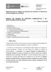
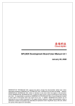
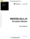
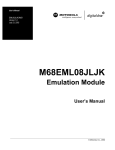
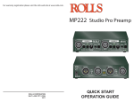
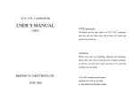
PCH8 Eight Channel
Summing Line Output
Converter
Instruction Manual
Peripheral Electronics®
A Division of AAMP of America™
13160 56th Court
Clearwater, Florida 33760
In U.S.: 866-788-4237
Outside U.S.: 727-572-9255 ext. 262
Email: [email protected]
©2007 AAMP of Florida™
Table of Contents
Chapter 1 – Getting Started
Pages
1.1 Introduction 1
1.2 PCH8 Features 1
Chapter 2 – General Installation
2.1 Before Installation 2
2.2 Installation 3-4
2.3 After Installation 5
Chapter 3 – Troubleshooting & Warranty
3.1 Troubleshooting 5
3.2 Warranty 6
3.3 Warning 6
Chapter 1 – Getting Started
1.1 Introduction
Congratulations on the purchase of your Peripheral PCH8 Line Output Converter (LOC). This
eight-channel LOC allows you to connect an aftermarket amplifier to a factory stereo—a critical
device for anyone looking to upgrade their amplified system without adding a new head unit.
We recommend you read this entire manual before beginning your installation.
1.2 PCH8 Features
Below is a list of specific PCH8 features. Use Figure 1 to help you identify where these features are located.
1. Output Level Controls: Let you adjust the input signals from your source unit to
match the amplifier volume.
2. Overdrive Indicator Light: Indicates when your signal level is just below clipping
your PCH8. When your system’s volume is turned as high as possible, the light should
flicker on and off.
3. Speaker Input Channels: Accept signals from the speaker-level outputs of your
source unit or amplifier. There are eight Speaker Input channels. Each input accepts
up to 400w.
4. Remote Output Connector: Provides a 12 volt output for external devices like signal
processors and external amplifiers. Also prevents turn-on pops.
5. Remote Input Connector: Allows your PCH8 to be turned on when auto turn-on is not
consistent.
6. +12V Input Connector: Connects your PCH8 to constant +12V.
7. Ground Input Connector: Connects your PCH8 to a good, verified chassis ground.
8. Main Pre-Amp Outputs: Connect the PCH8 to a signal processor, crossover, or
amplifier. Maximum output voltage 9.5vrms.
9. Channel Summed Indicator Lights: Indicate which channels are being summed into
the Main Pre-Amp Outputs.
10. Remote Subwoofer Level Control Input: Connects included remote to control
the subwoofer output of your PCH8 from your dashboard.
11. Power Light: Indicates that the unit is powered up.
8
2
1
Figure 1: PCH8 top cover
9
3
10
4
5
11
6
7
1
Chapter 2 – General Installation
2.1 Before Installation - Setting the Jumpers
Before installing your PCH8, you need to choose which Speaker Input channels will be summed
into the Main Outputs. You will also determine the best audio ground isolation setting. Follow the
steps below to customize your PCH8 settings. For help, see Figure 2 below.
Summing Your Input Signals
1.Remove all housing screws and the PCH8 cover.
2.Identify the corresponding jumper blocks and speaker inputs. The JK1
Jumper Block corresponds with the Ch 2 Speaker Input. The JK2 Jumper
Block corresponds with the Ch 3 Speaker Input. The JK3 Jumper Block
corresponds with the Ch 4 Speaker Input.
3.The default setting for the JK1, JK2, and JK3 jumper blocks is set to “Separate”
mode. Move those individual JK1, JK2, and JK3 Jumpers you want summed to the
“Summed” position. Be sure to move all three jumpers together.
Making Audio Ground Setting
1.The Audio Ground Isolation Jumpers provide additional grounding options in the
event that your system encounters alternator noise. This can happen when your
source unit and amplifier are using different grounding connections, there by creating
a “ground loop.” In some cases, changing your ground isolation setting will eliminate
this noise. Be sure to turn your system off before you adjust this setting.
2.Reattach the PCH8 cover.
Line Outputs
LED’s
JK 1
JK 2
Isolated
JK 3
Summed
Ground
Separate
PCH8
Summing Jumper Locations
Main
CH 2
CH 3
Speaker Inputs
Figure 2: Inside view of PCH8
(Not to scale)
2
Ch 4
Ground
Isolation
200 Ω
2.2 Installation
Below are the installation steps for your PCH8. To ensure proper installation, please follow the
steps closely in the order provided. For help, see Figure 3.
Positioning Your PCH8
1.
2.
3.
Choose an install location: Choose a location that gives you convenient access to
your PCH8 Output Level controls so you can easily control your system’s
sound quality.
Mark the location: Once you’ve chosen where to position your PCH8, mark
the mounting holes.
Secure the chassis: Drill a few small pilot holes and secure your PCH8
mounting bracket with the screws provided.
Installing the Sub Remote Control
1.
2.
To mount under dash: Choose a location under the dash and mark two mounting
holes for the mounting clip included with your PCH8. Then drill pilot holes and attach the
mounting clip.
To mount flush with dash panel: First, remove the sub remote control from the
housing by pulling forward on the control knob and front housing panel. Disassemble
the circuit board and control knob. In the dash board, drill a 9/32 hole for the control.
Reconnect the sub remote control parts to the dash board.
Connecting the Power Wiring
1. Disconnect the battery: Before installing your PCH8, disconnect the negative
terminal from the automobile’s battery.
2. Connecting the +12V Connector: Run a 12 to 18 gauge wire from the 12+
connector on your PCH8 to the battery. Fuse it at 1 amp with the fuse included
with your PCH8.
3. Connecting the Ground Connector: Run the same gauge wire used to
connect the +12 volt from the Ground connector on your PCH8 either to the
negative terminal of the battery, a ground bus, or a verified ground location.
4. Connecting the Remote-In Connector: Run an 18 to 22 gauge wire from the
Remote-In connector on your PCH8 to the source unit’s remote turn-on or
other trigger. Keep in mind that you may not need to use the Remote-In
connector, since your PCH8 signal sensor automatically turns on when it
detects a signal at the Main speaker-level inputs.
5. Connecting the Remote-Out Connector: If using the PCH8 to turn on any
external signal processors or amplifiers, run an 18 to 22 gauge wire from the
Remote-Out connector on your PCH8 to the remote turn-on input of the
processors or amplifiers. Depending on how many processors you use, you
may need to connect this wire to a relay and route 12 volts from another
source.
Note: Once you’ve established power, a green Channel Summed Indicator light
will appear next to those Main Pre-Amp channels you have summed. Also, your
Power Light should be bright red if your power wires are connected properly.
3
Connecting the Audio Wiring
1. Connect the speaker wires: Following the appropriate diagram in Figure 3, run your
speaker wires to your PCH8 Speaker Input channels. Make sure the positive (+) and
negative (-) connections match. If necessary, refer to the factory service manual or
wiring-harness to locate your system’s speaker wires.
Note: If your source unit has front, rear, and subwoofer speaker-level outputs, connect
them to the Main, Ch 2, and Ch 4 inputs on your PCH8. If you are unsure at all how to
connect your speaker wiring, we recommend seeking professional installation.
Connecting the Main Pre-Amp Outputs
1. Connect the Main Pre-Amp Outputs: Following the appropriate diagram in Figure 3,
run RCA connectors from the Main Pre-Amp Outputs to the inputs of your amplifiers.
Warning: Never connect the Main Pre-Amp Outputs directly to the speakers.
Standard Function
RCA Connectors
AMPLIFIER
Front Speakers
Factory Installed Radio
Sub Control
FAV
EQ
MENU
CAT
EJECT
LOAD
BAND
SEEK
SEEK
REV
FWD
AMPLIFIER
CD
AUX
Speaker Level
Signals
Rear Speakers
Front
Rear
Sub
AMPLIFIER
Subwoofer
Summing Function
RCA Connectors
Factory Installed Radio
FAV
EQ
MENU
LOAD
BAND
AMPLIFIER
CAT
EJECT
SEEK
SEEK
REV
FWD
Front Speakers
CD
AUX
Data Bus
Cable
AMPLIFIER
Factory Installed Amplifier
AMPLIFIER
Rear Speakers
Front Tweeter
Front Mid Ranged
Rear Full Ranged
Subwoofer
Speaker Level
Signals
AMPLIFIER
Subwoofer
4
Figure 3: Example connection diagrams
2.3 After Installation
Now it’s time to customize your stereo’s sound. To do this, you’ll need to make sure your speaker
levels are balanced and your system levels are properly matched. For best results, we recommend
using a pink noise CD and a real time audio analyzer (RTA).
Adjusting Levels of Summed Outputs
1.
2.
Play your CD on your disc player and turn up the volume until a signal appears on your
RTA.
Adjust the PCH8 Output Level controls so that your RTA reveals a smooth or flat
response curve.
Matching the Levels
1.
2.
3.
4.
5.
6.
7.
8.
9.
Set the fader and balance controls on your source unit to their center position. Set
subwoofer outputs to low.
Unplug the RCA connectors from your PCH8 Main Pre-Amp Outputs.
Play music from your source unit at ¾ its full volume. Remember, you should not hear
any music at this time.
Adjust your PCH8 Output Level controls until the Overdrive light appears. Don’t worry
if the Overdrive light does not turn on. Most likely, the signal from your source unit is not
strong enough to trigger the display. This is ok.
Turn your amplifier’s input gains to low.
Turn the volume on your source unit to low.
Reconnect the RCA connectors to your PCH8 Main Pre-Amp Outputs.
Increase the volume on your source unit to 3/4 volume.
Increase the amplifier gains until the sound is slightly distorted, then stop.
Chapter 3 – Troubleshooting & Warranty
3.1 Troubleshooting
If you’re having trouble with your PCH8 once it’s installed, check out the chart below.
Problem
PCH8 has no power.
Solution
Verify that the power wires and remote turn-on wires
are connected. Also verify that a fuse has not blown
and that a signal is present.
PCH8 occasionally turns off.
Radio is not compatible with auto turn-on circuit. Connect
12-volt trigger to the Remote-In connector on your PCH8
to manually turn on unit.
System hisses or sounds distorted.
PCH8 output level controls or amplifier gains are set
too high. Follow instructions for “Matching the Levels”
in Section 2.3
System occasionally pops.
Use the Remote-Out connector on your PCH8 to turn
your amplifiers on or off and eliminate any timing issues.
PCH8 has a low output.
Input signal from source radio may be low. First, turn
up the gains on your PCH8. As an alternative, consider
adding a pre-amp line driver to increase the signal level
to the PCH8.
Overdrive light doesn’t turn on
This isn’t actually a problem. The Overdrive light should
when the system is playing fine.
only turn on when your PCH8 pre-amp signal is at a
maximum level.
5
3.2 Warranty
One Year Limited Warranty
The quality controls used in the manufacture of this product will ensure your satisfaction. This warranty applies only to
the original purchaser of this product from an authorized Peripheral Electronics dealer.
This warranty covers any supplied or manufactured parts of this product that, upon inspection by Peripheral Electronics
authorized personnel, is found to have failed in normal use due to defects in material or workmanship. This warranty
does not apply to installation expenses.
Attempting to service or modify this unit, or operating this unit under conditions other than the recommended voltage,
will render this WARRANTY VOID.
Unless otherwise prescribed by law, Peripheral Electronics shall not be liable for any personal injury, property damage
and/or any incidental or consequential damages of any kind (including water damage) resulting from malfunctions,
defects, misuse, improper installation or alteration of this product.
All parts of this Peripheral Electronics product are guaranteed for a period of 1 year as follows:
Within the first 12 months from the date of purchase, subject to the conditions above,
Peripheral Electronics will repair or replace the product at their discretion, if it is defective in material or workmanship, providing it is returned to an Authorized Peripheral Electronics Dealer, with PROOF OF PURCHASE from
an authorized Peripheral Electronics dealer.
3.3 Warning
This equipment may be reset by unintentional electrostatic discharge during operation. Exposure to direct sunlight or
extreme heat may cause damage or malfunction.
www.peripheralelectronics.com
Peripheral Electronics®
A Division of AAMP of America™
13160 56th Court
Clearwater, Florida 33760
In U.S.: 866-788-4237
Outside U.S.: 727-572-9255 ext. 262
Email: [email protected]
©2007 AAMP of Florida™