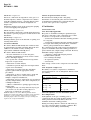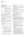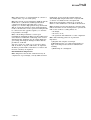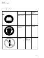
1
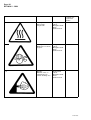
BRITISH STANDARD Compressors and vacuum pumps Ð Safety requirements Part 1. Compressors The European Standard EN 1012-1 : 1996 has the status of a British Standard ICS 23.140 NO COPYING WITHOUT BSI PERMISSION EXCEPT AS PERMITTED BY COPYRIGHT LAW | | | | | | | | | | | | | | | | | | | | | | | | | | | | | | | | | | | | | | | | | | | | | | | | | | | | | | | | | | | | | | | | | | | | | | | | | | | | | | | | | | | | | | | | | | | | | | | | | | | | | | | | | | | | | | | | | | | | | | | | | | | | | | | | | BS EN 1012-1 : 1997 BS EN 1012-1 : 1997 Committees responsible for this British Standard The preparation of this British Standard was entrusted to Technical Committee MCE/8, Compressors, pneumatic tools and pneumatic machines, upon which the following bodies were represented: British Compressed Air Society Engineering Equipment and Materials Users Association Institute of Marine Engineers Institution of Gas Engineers Institution of Mechanical Engineers Institution of Plant Engineers South Wales Institute of Engineers This British Standard, having been prepared under the direction of the Engineering Sector Board, was published under the authority of the Standards Board and comes into effect on 15 January 1997 BSI 1997 Amendments issued since publication Amd. No. The following BSI references relate to the work on this standard: Committee reference MCE/8 Draft for comment 93/703167 DC ISBN 0 580 26279 0 Date Text affected BS EN 1012-1 : 1997 Contents Committees responsible National foreword Foreword Text of EN 1012-1 BSI 1997 Page Inside front cover ii 2 3 i BS EN 1012-1 : 1997 National foreword This British Standard has been prepared by Technical Committee MCE/8 and is the English language version of EN 1012 Compressors and vacuum pumps Ð Part 1 : 1996 Compressors, published by the European Committee for Standardization (CEN). EN 1012-1 was produced as a result of international discussions in which the United Kingdom took an active part. Cross-references Publication referred to Corresponding British Standard EN 292-1 : 1991 EN 292-2 : 1991 BS EN 292 Safety of machinery Ð Basic concepts Ð General principles for design Part 1 : 1991 Basic terminology, methodology Part 2 : 1991 Technical principles and specifications EN 294 BS EN 294 : 1992 Safety of machinery Ð Safety distances to prevent danger zones to be reached by the upper limbs EN 349 BS EN 349 : 1993 Safety of machinery Ð Minimum gaps to avoid crushing of parts of the human body EN 418 BS EN 418 : 1992 Safety of machinery Ð Emergency stop equipment Ð Functional aspects Ð Principles for design EN 563 BS EN 563 : 1994 Safety of machinery Ð Temperatures of touchable surfaces Ð Ergonomic data to establish temperature limit values for hot surfaces EN 626 BS EN 626 Safety of machinery Ð Reduction of risks to health from hazardous substances emitted by machinery Part 1 : 1995 Principles and specifications for machinery manufacturers Part 2 : 1996 Methodology leading to verification procedures ENV 1070 DD ENV 1070 : 1993 Safety of machinery Ð Terminology EN 50014 BS EN 50014 : 1993 Electrical apparatus for potentially explosive atmospheres Ð General requirements EN 50081-2 BS EN 50081 Electromagnetic compatibility Ð Generic emission Part 2 : 1994 Industrial environment EN 50082-2 BS EN 50082 Electromagnetic compatibility Ð Generic immunity Part 2 : 1995 Industrial environment EN 61310-1 ii BS EN 61310 Safety of machinery Ð Indication, marking and actuation Part 1 : 1995 Requirements for visual, auditory and tactile signals BSI 1997 BS EN 1012-1 : 1997 EN 60204-1 ISO 3457 BS EN 60204 Safety of machinery Ð Electrical equipment of machines Part 1 : 1993 Specification for general requirements BS EN ISO 3457 : 1995 Earth-moving machinery Ð Guards and shields Ð Definitions and specifications ISO 3857-1 BS 5791 Glossary of terms for compressors, pneumatic tools and machines Part 1 : 1979 General ISO 3857-2 Part 2 : 1979 Compressors ISO 6743-3A BS 6413 Lubricants, industrial oils and related products (Class L) Part 3 Classification for family D (compressors) Section 3.1 : 1988 Air compressors ISO 6743-3B Part 3 Classification for family D (compressors) Section 3.2 : 1989 Gas and refrigeration compressors ISO 7000 BS 7324 : 1990 Guide to graphical symbols for use on equipment Ð Index and synposis Compliance with a British Standard does not of itself confer immunity from legal obligations. BSI 1997 iii iv blank EN 1012-1 EUROPEAN STANDARD NORME EUROPEÂENNE EUROPAÈISCHE NORM April 1996 ICS 23.140 Descriptors: Air compressors, safety requirements, safety of machines, accident prevention, definitions, failure, safety measures, design, construction, installation, utilization, maintenance, verification, name plates English version Compressors and vacuum pumps Ð Safety requirements Ð Part 1: Compressors Compresseurs et pompes aÁ vide Ð Prescriptions de seÂcurite РPartie 1: Compresseurs Kompressoren und Vakuumpumpen Ð Sicherheitsanforderungen Ð Teil 1: Kompressoren This European Standard was approved by CEN on 1996-03-13. CEN members are bound to comply with the CEN/CENELEC Internal Regulations which stipulate the conditions for giving this European Standard the status of a national standard without any alteration. Up-to-date lists and bibliographical references concerning such national standards may be obtained on application to the Central Secretariat or to any CEN member. The European Standards exist in three official versions (English, French, German). A version in any other language made by translation under the responsibility of a CEN member into its own language and notified to the Central Secretariat has the same status as the official versions. CEN members are the national standards bodies of Austria, Belgium, Denmark, Finland, France, Germany, Greece, Iceland, Ireland, Italy, Luxembourg, Netherlands, Norway, Portugal, Spain, Sweden, Switzerland and United Kingdom. CEN European Committee for Standardization Comite EuropeÂen de Normalisation EuropaÈisches Komitee fuÈr Normung Central Secretariat: rue de Stassart 36, B-1050 Brussels 1996 Copyright reserved to CEN members Ref. No. EN 1012-1 : 1996 E Page 2 EN 1012-1 : 1996 Foreword 4.6 This European Standard has been prepared by Technical Committee CEN/TC 232, Compressors Ð Safety, the secretariat of which is held by SIS. This European Standard shall be given the status of a national standard, either by publication of an identical text or by endorsement, at the latest by October 1996, and conflicting standards shall be withdrawn at the latest by October 1996. This European Standard has been prepared under a mandate given to CEN by the European Commission and the European Free Trade Association and supports essential requirements of EU Directive(s). For the relationship with EU Directive(s), see informative annex ZA, which is an integral part of this standard. According to the CEN/CENELEC Internal Regulations, the national standards organizations of the following countries are bound to implement this European Standard: Austria, Belgium, Denmark, Finland, France, Germany, Greece, Iceland, Ireland, Italy, Luxembourg, Netherlands, Norway, Portugal, Spain, Sweden, Switzerland, and the United Kingdom. The responsibility of CEN/TC 232 includes coordination of safety standards with CEN/TC 182, Refrigerating systems, safety and environmental requirements, and CEN/TC 234, Gas supply. Annexes A, C and ZA to this European Standard are informative, and annex B is normative. The standard is divided in two parts: ± EN 1012-1 Compressors ± EN 1012-2 Vacuum Pumps Contents Foreword 1 Scope 2 Normative references 3 Definitions 3.1 General definitions 3.2 Definitions of specific compressors 4 List of hazards specific to compressors 4.0 Introduction 4.1 Mechanical hazards 4.2 Electrical hazards 4.3 Thermal hazards 4.4 Noise 4.5 Hazards generated by used or exhausted materials and substances processed 3 3 4 4 4 5 5 5 5 5 5 Hazards generated by neglecting ergonomic principles in machine design 4.7 Hazards caused by failure of energy supply, breaking down of machinery parts and other functional disorders 4.8 Hazards caused by missing or incorrectly positioned safety related measures and means 5 Safety requirements and measures for all types of compressors 5.1 Mechanical safety 5.2 Electrical safety 5.3 Thermal safety 5.4 Noise 5.5 Materials and substances processed, used or exhausted 5.6 Ergonomic principles 5.7 Failure of energy supply, breaking down of machinery parts and other functional disorders 5.8 Safety related measures and means 6 Markings, signs, written warnings 6.1 Generally applicable 6.2 Data plate 6.3 Signs and warnings 7 Instructions for use 7.1 Generally applicable 7.2 Instruction Manual 7.3 Service Manual 7.4 List of parts used for service 8 Verification 8.1 Pressure tests 8.2 Leak tightness test for hazardous gases 8.3 Noise measurements 8.4 Structure of verification Annexes A (informative) Bibliography B (normative) Fires and explosions in the pressure system C (informative) Labels, signs and tags ZA (informative) Clauses of this European Standard addressing essential requirements or other provisions of EU Directives 6 6 6 7 7 7 8 8 8 11 11 12 14 14 14 14 14 14 15 16 16 16 16 16 17 17 18 18 20 25 5 BSI 1997 Page 3 EN 1012-1 : 1996 1 Scope This standard is applicable to all types of compressors. The standard lists the significant hazards associated with compressors and specifies safety requirements applicable to the design, installation, operation, maintenance and dismantling of compressors during their foreseeable lifetime and subsequent disposal. Compressors intended for use in special applications shall also comply with any specific standards relating to those applications. This standard specifies safety requirements for all compressors and additional requirements for the following specific types: Compressors for various types of gases ± oil-lubricated air compressors; ± oil-flooded air compressors; ± oil-free air compressors; ± compressors for handling hazardous gases (gas compressors); ± compressors for handling oxygen; ± compressors for handling acetylene. Compressors for extreme temperatures and pressures ± high pressure compressors, over 40 bar; ± compressors for low inlet temperatures, below 0 ÊC. Other types of compressors ± large compressors (over 1000 kW input power); ± portable and skid-mounted air compressors; ± compressors exposed for potentially explosive atmospheres. Exceptions ± The following compressors are excluded from the scope of this standard: ± compressors having a shaft input power of less than 0,5 kW; ± compressors for gases other than acetylene, having a maximum allowable working pressure of less than 0,5 bar; ± refrigerant compressors used in refrigerating systems or heat pumps as defined in EN 378. 2 Normative references This European standard incorporates by dated or undated reference, provisions from other publications. These normative references are cited at the appropriate places in the text and the publications are listed hereafter. For dated references, subsequent amendments to or revisions of any of the publications apply to this European standard only when incorporated in it by amendment or revision. For undated references the latest edition of the publication referred to applies. BSI 1997 EN 292-1 : 1991 Safety of machinery Ð Basic concepts Ð General principles for design Ð Part 1: Basic terminology, methodology EN 292-2 : 1991 Safety of machinery Ð Basic concepts Ð General principles for design Ð Part 2: Technical principles and specifications EN 294 Safety of machinery Ð Safety distances to prevent danger zones to be reached by the upper limbs. EN 349 Minimum distances to avoid crushing of parts of the human body EN 378 Refrigerating systems and heat pumps Ð Safety and environmental requirements EN 418 Safety of machinery Ð Emergency stop equipment Ð Functional aspects EN 563 Temperatures of touchable surfaces Ð Ergonomic data to establish temperature limit values for hot surfaces EN 626 Safety of machinery Ð Principles for machinery manufacturers on the reduction of risk to health from hazardous substances emitted by machinery EN 837-1 Pressure gauges Ð Part 1: Bourdon tube pressure gauges Ð Dimensions, metrology, requirements and testing EN 953 Safety of machinery Ð Guarding of machinery Ð Fixed and movable guards EN 1127-1 Safety of machinery Ð Fires and explosions Ð Part 1: Explosion prevention and protection ENV 1070 Safety of Machinery Ð Terminology EN 12076 Acoustics Ð Noise test code for compressors and vacuum pumps (Grade 2) EN 50014 Electrical apparatus for potentially explosive atmospheres Ð General requirements EN 50081-2 Electromagnetic compatibility Ð Generic emission Ð Part 2: Industrial environment EN 50082-2 Electromagnetic compatibility Ð Generic immunity Ð Part 2: Industrial environment Page 4 EN 1012-1 : 1996 EN 61310-1 Safety of machinery Ð Indication, marking and actuation Ð Part 1: Requirements for visual, auditory and tactile signals (IEC 1310-1 : 1995) EN 60204-1 Electrical equipment of industrial machines Ð Part 1: General requirements ISO 3457 Earth-moving machinery Ð Guards and shields Ð Definitions and specifications ISO 3864 Safety colours and safety signs ISO 3857-1 Compressors, pneumatic tools and machines Ð Vocabulary Ð Part 1: General ISO 3857-2 Compressors, pneumatic tools and machines Ð Vocabulary Ð Part 2: Compressors ISO 4126-1 Safety valves Ð Part 1: General requirements ISO 4871 Acoustics Ð Declaration and verification of noise emission values of machinery and equipment ISO 6743-3A Lubricants, industrial oils and related products ( Class L) Ð Classification Part 3A: Family D (Compressors) ISO 6743-3B Lubricants, industrial oils and related products ( Class L) Ð Classification Part 3B: Family D (Gas and refrigeration compressors) ISO 7000 Graphical symbols for use on equipment Ð Index and synopsis ISO/TR 11688-1 Acoustics Ð Recommended practice for the design of low-noise machinery and equipment Ð Part 1: Planning IEC 417 Graphical symbols for use on equipment 3 Definitions For the purposes of this standard, the definitions given in ENV 1070 apply. Definitions specifically needed for compressors are listed below and in the standard ISO 3857-1 and ISO 3857-2. 3.1 General definitions 3.1.1 compressor A machine which compresses air, gases or vapours to a pressure higher than the inlet pressure. A compressor comprises the bare compressor itself, the prime mover, and any component or device supplied which is necessary for safe operation of the compressor. 3.1.2 pressure Pressure in this standard means effective (gauge) pressure unless otherwise stated. NOTE. The unit bar for pressure is used. 1 bar = 100 kPa. 3.1.3 nominal discharge pressure The pressure at the outlet of the compressor, as specified by the manufacturer. 3.1.4 maximum allowable working pressure The maximum operating pressure as specified by the manufacturer. 3.1.5 maximum allowable working temperature The maximum operating temperature, as specified by the manufacturer. 3.1.6 hazardous gas or vapour Gas or vapour with chemical, radioactive or biological properties (such as flammable, explosive, unstable, pyrogenic, corrosive, caustic, toxic, carcinogenic), which generate hazards by reactions inside the compressor or through dispersal or through reactions with the environment. A hazardous gas may be a mixture of gases with these properties. 3.1.7 tripping Automatic stopping of a compressor initiated by limiting device. 3.2 Definitions of specific compressors 3.2.1 air compressor A compressor intended for compression of air. 3.2.2 oil-free air compressor A compressor design in which the compressed air does not come in contact with oil. 3.2.3 oil-lubricated air compressor A compressor design in which the compressed air may come in contact with oil but excluding oil-flooded air compressors. 3.2.4 oil-flooded air compressor A compressor design in which the compressed air and the oil are mixed. 3.2.5 gas compressor A compressor for handling hazardous gases as defined under 3.1.6. 3.2.6 oxygen compressor A compressor for handling pure oxygen, or oxygen-rich mixture of more than 70 mole per cent oxygen. 3.2.7 acetylene compressor A compressor intended for handling acetylene. 3.2.8 high pressure compressor A compressor for maximum allowable working pressures above 40 bar. BSI 1997 Page 5 EN 1012-1 : 1996 3.2.9 low temperature compressor A compressor for continuous handling of media other than air, having an inlet temperature below 0 ÊC. 4.2 Electrical hazards 3.2.10 large compressor A compressor with an input shaft power above 1000 kW. ± electrical contact, direct or indirect ± electrostatic phenomena ± external influences on electrical equipment 3.2.11 portable compressor A compressor which is wheel mounted and can be towed. 4.2.1 Generally applicable 4.2.2 Gas compressors 3.2.12 skid-mounted compressor A compressor which is mounted on skids and which can be towed short distances or transported. ± sparks 4 List of hazards specific to compressors ± electric installation 4.0 Introduction Hazards listed in clause 4 are: ± hazards common to all compressors and which are listed under the heading `Generally applicable'; ± hazards which are unique for specific compressors and which are listed under the relevant headings. 4.3 Thermal hazards 4.1 Mechanical hazards 4.4 Noise Reference to safety requirement 4.1.1 Generally applicable ± ± ± ± ± ± ± cutting and severing drawing in, trapping or entanglement friction or abrasion high pressure fluid injection ejection of parts loss of stability slip, trip and fall 5.1.1.1, 5.8.2 5.1.1.1, 6.3.1 5.1.1.1 5.1.2.1 5.1.3 5.1.4.1 5.1.5 5.1.1.2, 7.2.9.4 BSI 1997 4.2.3 Portable and skid-mounted air compressors 5.2.1.1 4.3.1 Generally applicable ± burns or scalds by flames or explosion 5.3 or possible contact by persons with hot or cold materials or surfaces 4.4.1 Generally applicable ± hearing loss and interference with communication 5.4.1, 7.2.4h ± environmental disturbance 5.4.2 4.5 Hazards generated by used or exhausted materials and substances processed 4.5.1 Generally applicable ± contact with, or inhalation of, harmful 5.5.1, 7.2.4 fluids, gases, mists, fumes and dust ± fire or explosion 5.5.3.1, 7.2.3 ± biological and micro-biological 5.5.4 substances 4.5.2 Air compressors 4.1.3 Portable and skid-mounted air compressors ± trapping and entanglement ± high pressure injection ± loss of stability 5.2.2 4.4.2 Construction site compressors 4.1.2 Large compressors ± drawing in, trapping or entanglement 5.2.1.1 5.2.2 5.2.3 ± fire and explosion 7.2.9.1b, c 7.2.9.1b, c 5.1.4.2, 7.2.9.1b 5.5.3.2, 5.5.3.3, 7.3 4.5.3 Gas compressors ± reaction, explosion or decomposition 5.5.2.2a, b of the gas inside the compressor ± reactions of the processed gas with 5.5.2.2b the environment due to leakage ± dispersal of the processed gas into the 5.5.2.2c environment Page 6 EN 1012-1 : 1996 4.5.4 Oxygen compressors ± reaction of the oxygen inside the compressor ± inadequate choice of materials for oxygen service ± inadequate choice of materials and design of valves for oxyen service ± lack of maintenance and cleaning ± emission of oxygen or oxygen enriched atmosphere 4.7.2 Gas compressors 5.5.2.3a ± break down of machinery parts 5.5.2.3b 4.7.3 Acetylene compressors 5.5.2.3c 5.5.2.3d 5.5.2.3e 5.5.2.4a, b 5.5.2.4c 4.5.6 High pressure compressors ± increased reactivity of gases, lubricants 5.5.2.5 and impurities at high pressure 4.5.7 Portable and skid-mounted air compressors ± contact with or inhalation of harmful gases ± fire or explosion ± refuelling 5.5.2.6 5.5.3.4 5.5.3.4 ± neglecting to use personal protection 7.2.4 equipment ± human errors resulting from unsuitable 5.6.1, 7.2.3 positioning of control devices and instruments 4.6.2 Portable and skid-mounted air compressors ± leakage ± loss of braking capacity ± falling when lifted ± breaking down, deterioration or bursting of delivery hose 5.7.2.4 5.7.2.5b 5.7.2.5a 7.2.9.1 4.8 Hazards caused by missing or incorrectly positioned safety related measures and means ± all kinds of guards ± all kinds of safety related devices ± starting and stopping devices ± safety signs and tags ± all kinds of information or warning devices ± energy supply disconnect devices ± emergency devices ± essential equipment and accessories for safe adjustment and maintenance 5.6.2 5.8.2 5.8.3 ± 5.8.7 5.8.1, 5.6 6.3.1 6 7.2.3 5.8.9 7.3 4.8.2 Gas compressors ± all kinds of safety related devices 4.7 Hazards caused by failure of energy supply, breaking down of machinery parts and other functional disorders 4.7.1 Generally applicable ± failure of energy supply ± failure of control system, e.g. unexpected start-up ± errors of fitting ± break down of machinery parts due to dynamic stresses, fatigue and cyclic pressure variation ± hazards resulting from leakages and gas discharges 4.7.4 High pressure compressors 4.8.1 Generally applicable 4.6 Hazards generated by neglecting ergonomic principles in machine design 4.6.1 Generally applicable ± tow bars with excessive down load 5.7.2.3 4.7.5 Portable and skid-mounted air compressors 4.5.5 Acetylene compressors ± decomposition of acetylene ± flammability of acetylene in gas mixture ± break down of machinery parts 5.7.2.2 5.8.1.2 4.8.3 Oxygen compressors ± all kinds of safety related devices 5.8.1.3 4.8.4 Large compressors 5.7.1.1 5.7.1.1 5.7.3 5.7.2.1 ± essential equipment and accessories for safe adjustment and maintenance 5.8.1.4, 6.3.2 4.8.5 Portable and skid-mounted compressors ± safety signs and tags 6.3.3 5.7.2.1 BSI 1997 Page 7 EN 1012-1 : 1996 5 Safety requirements and measures for all types of compressors 5.1 Mechanical safety 5.1.1 Cutting, severing, drawing in, trapping, entanglement, friction and abrasion 5.1.1.1 Generally applicable Guards to protect against contact with moving parts shall be installed. For specification of guards see 3.22 of EN 292 -1 and clause 4 of EN 292-2 and EN 953 and EN 294. The hazards of cutting and severing, friction and abrasion shall be minimized. See 3.1 and 3.2 of EN 292-2. Atmospheric inlets and inspection openings on inlets shall be provided with protective devices so that persons or foreign matter cannot be drawn in. See EN 294, EN 349 and EN 953. 5.1.1.2 Large compressors Openings, in air and gas inlet ducts, intended for internal inspection and maintenance by people inside the ducts shall be provided with interlocking devices or systems to prevent starting whilst openings are not fully and properly closed. The doors shall be lockable in the open position. 5.1.2 Fluid injection 5.1.2.1 Generally applicable The hazard of fluid injection into the human body shall be minimized by: ± designing all auxiliaries which come within the scope of pressure equipment codes, e.g. coolers, hoses, pipes, separators, silencers and traps in accordance with the applicable codes; ± testing pressure-containing parts on the gas side of the compressor according to subclause 8.1; ± designing and supporting integral pipework, hoses and auxiliaries to withstand vibration, thermal expansion and their own mass, foreseeable external forces, influence of contaminants and external chemical substances; ± ensuring that all piping which is in a position likely to be damaged is protected, robust and sufficiently supported; ± taking measures to prevent damage from freezing during off-load or non-operational periods. Providing drainage facilities to ensure that liquid can be removed from piping and accessories such as water jackets, coolers, pulsation dampers and air receivers. See also subclause 7.2. 5.1.2.2 High pressure compressors The design of pressure relief devices, and the location of vents shall take account of the characteristics and velocity of gas likely to be discharged. BSI 1997 5.1.3 Ejection of parts Moving parts shall be designed and mounted in such a way that in all foreseeable modes of operation the ejection of parts is avoided. 5.1.4 Loss of stability 5.1.4.1 Generally applicable Compressors shall be provided with means to allow them to be adequately mounted and secured. 5.1.4.2 Portable and skid-mounted air compressors The centre of gravity shall be low enough to ensure that the compressor remains stable, without tipping or slipping, when used within the manufacturer's limits which shall be stated in the instructions. Tyres of a compressor shall be rated to carry the maximum gross mass of the compressor at the highest towing speed specified by the manufacturer. All tyres shall be of the same construction. NOTE. Gross mass is defined as the maximum specified mass of the compressor including tools, equipment and fuel. The support leg or jockey wheel shall be of adequate strength. It shall be possible to securely lock it in both the support and towing positions. 5.1.5 Slip, trip and fall Platforms, stairs and railings that are an integral part of the compressor shall be positioned so that access is available to all areas where routine maintenance or operator's inspections are necessary. Their positioning shall not interfere with maintenance of any parts with respect to accessibility or lifting. Open sides of platforms elevated by more than 1 m shall be guarded with safety rails set at about 1050 mm and 600 mm above the platform and provided with a toe board about 100 mm high. Stairs or ladders of more than four steps shall have a safety rail on both sides. 5.2 Electrical safety 5.2.1 Electrical installation 5.2.1.1 Generally applicable The electrical installation of a compressor shall fulfil the requirements of EN 60204-1. Protection devices and switches shall be so designed and connected as to fulfil the requirements of `fail-safe'. The overcurrent protection of the power circuit may be installed outside the compressor enclosure on site. In such a case the Instruction Manual shall state that the user has to make provision for the installation of the overcurrent protection of the power circuit. Where the compressor is not fitted with an electrical disconnecting device, the Instruction Manual shall specify that this device is to be provided by the user. Wiring harnesses shall: ± be adequately secured and protected; ± not be in contact with hot surfaces; ± have adequate electrical insulation. Page 8 EN 1012-1 : 1996 For compressors to be installed in potentially explosive atmospheres the electrical equipment shall comply with EN 50014. 5.2.1.2 Portable and skid-mounted air compressors Batteries shall be firmly secured and provided with lifting points. They shall be mounted so there is no risk of electrolyte splashing on personnel and surrounding equipment. The terminals shall be insulated according to 4.10 and 4.11 of ISO 3457. A suitable overcurrent protection device shall be provided in the electrical installation to protect the wiring harness and the electric equipment. This excludes the starter and charging circuit. 5.2.2 Electrostatic phenomena The build-up of electrostatic charges shall be avoided by earthing all conductive stationary components, if there is a risk to persons or the possibility of an effective ignition source developing. 5.2.3 External influences on electrical equipment The safety system and other electrical equipment shall be so designed and constructed that they cannot give rise to a hazardous situation in case of disturbances such as: ± short circuiting; ± external impacts; ± variations in the supply voltage; ± electromagnetic fields (see EN 50081-2 and EN 50082-2); ± earthing faults. 5.3 Thermal safety Where high or low temperature of the processed medium, lubricant or cooling medium can cause a hazard to personnel, the temperature shall be monitored and if the limits are exceeded the compressor shall be brought to a safe condition. Pipework or other parts with an external surface temperature above 70 ÊC or below ±10 ÊC and which may be accidentally touched by personnel during normal operation of the machine shall be guarded, insulated or carry an adequate warning. (See EN 563). Other high temperature pipework shall be clearly marked in accordance with annex C. Any piping shall be free to move with changing temperature and hot piping shall not be in contact with wood or flammable material. Compressors installed in an area with potentially explosive atmosphere must have limited surface temperatures and any other ignition sources shall be avoided, see EN 50014 and EN 1127-1. 5.4 Noise 5.4.1 Generally applicable Design considerations shall be given to noise reduction, taking into account ISO/TR 11688-1. Design shall be such that continuous full load operation is possible at the maximum specified ambient temperature, with all the doors and access covers closed. 5.4.2 Construction site compressors The noise emission level shall comply with the requirements for construction site equipment. 5.5 Materials and substances processed, used or exhausted 5.5.1 Liquid shock If liquid resulting from injection, priming or condensation can be present or be formed, adequate separators, traps and draining facilities shall be installed. If this equipment is not part of the compressor the Instruction Manual shall state that this equipment shall be installed outside the compressor. 5.5.2 Gases and substances processed 5.5.2.1 Generally applicable Freezing of coolant, effects on the lubrication or ingested liquid due to low temperature of the media being compressed or of the environment at starting, stopping or unloading conditions shall be prevented by suitable means. 5.5.2.2 Gas compressors For gases or vapours other than those specifically treated in this standard, advice on hazards shall be sought from competent bodies and precautions taken. a) Hazards caused by reactions of the gas inside the compressor shall be avoided as applicable by: ± limiting the compression temperature by design and by installing tripping devices on the discharge of each casing or cylinder; ± preventing ignition hazard, e.g. hot surfaces or friction; ± choice of suitable lubricant and/or use of sparkless material pairing where friction is possible; ± using materials resistant to corrosion caused by the processed gas; ± arranging connections so that adequate purging of the compressor system with inert gas can be achieved; ± using filters or other appropriate measures to avoid solid impurities in the processed gas; ± ensuring that the compressor installation undergoes a leak tightness test at commissioning. b) If the requirements of clause a) cannot be fulfilled or are insufficient and there is a risk from decomposition of the gas or of an explosion in the gas, the system shall be built to resist the resulting pressure. If this is not possible, the Instruction Manual shall state that personnel shall not have access to the danger zone. BSI 1997 Page 9 EN 1012-1 : 1996 c) The gas dispersal into the environment shall be minimized by the following measures: ± preventing leakage of harmful or flammable gases; ± providing double sealing with intermediate venting or with a sealing medium; ± using gaskets suitable for the gases processed at prevailing pressures and temperatures; ± neutralizing, diluting to a safe level or venting into a safe area; ± taking precautions for handling polluted lubricants, drainages and deposits. 5.5.2.3 Oxygen compressors An oxygen enriched atmosphere creates conditions for health and fire hazards in the installation area and the following safety measures for the compressors shall be taken as a minimum. a) Ignition points shall be avoided by: ± ensuring adequate clearance between moving parts; ± selecting suitable materials; ± limiting the quantity and size of particles and impurities in the oxygen stream; ± not allowing oil and grease in the oxygen stream; ± avoiding corrosion, particularly by minimizing moisture; ± preventing any contact between oxygen and substances having combustible properties, mainly oil and greases; ± limiting the oxygen discharge temperature by design and by installation of a shutdown device; ± limiting the oxygen velocity in pipes; ± ensuring no severe bends or sharp interior edges; ± providing adequate cooling. b) The choice of materials in oxygen compressors shall be optimized under consideration of the following characteristics: ± high ignition temperature; ± high thermal conductivity; ± high specific heat capacity; ± low specific heat of combustion; ± adequate corrosion resistance; ± recognized quality for oxygen service of non-metallic materials e.g. gaskets or seals; ± coolants and lubricants that can come into contact with oxygen shall be of a quality recognized as not being flammable in oxygen service. c) The following are specified for piping and valves: ± carbon steel pipes can be used depending on oxygen pressure and velocity, based on documented values accepted in the oxygen industry; ± valves shall be designed for low friction flow and operation; BSI 1997 ± isolating and unloading valves inside the danger zone shall be remotely operated; ± valves shall be designed so that spindles are secure against withdrawal. d) Maintenance and cleaning: ± provisions shall be made to allow thorough inspection and cleaning of the compressor, including the cooling jackets; ± connections, when integral with the compressor, shall be arranged so that purging of the compressor system with dry, oil-free air or inert gas can be carried out. Where such connections are not provided by the supplier the Instruction Manual shall instruct the user that such purging is necessary; ± components for oxygen service shall be free of particles and rust and free from oil and grease other than lubricants recognized for oxygen service. e) Hazard due to emission of oxygen: ± all released gases, purges, drainage and leakages containing oxygen shall be discharged without hazard to personnel and provisions made for adequate dilution; ± the venting of any oil system shall be separated from any discharge with a high oxygen content. 5.5.2.4 Acetylene compressors Acetylene is a highly flammable and chemically unstable gas. It may spontaneously decompose resulting in deflagration with a pressure increase about 11 times the initial pressure, or can detonate with a pressure increase up to 350 times the initial pressure. a) To limit the hazards and the consequences of decomposition the following precautions shall be taken: ± limit the capacity or the power of each compression unit; ± the diameter and length of the gas piping shall be as small as practicable; ± consideration of installation of flash arrestors at the inlet and outlet of the compressor system. b) The risk of decomposition shall be minimized by: ± considering the pressure and temperature of the acetylene to avoid liquefaction; ± limiting the compression temperature, by design, to a maximum of 140 ÊC under any foreseeable circumstances; ± avoiding hot spots by applying suitable lubrication, low piston speed, cooling and precautions to preclude impurities or debris of hard material; ± avoiding the presence of catalytic agents, which promote decomposition, e.g. iron rust, pipe scale; ± using materials which do not react with acetylene or other components in the processed gas: Page 10 EN 1012-1 : 1996 1) prohibited materials: ± copper and copper alloys with more than 70 % copper; ± for filter meshes, any copper alloy; ± silver and any silver alloy; ± mercury; 2) prohibited materials in presence of acetylene with lime and ammonia impurities: ± aluminium and its alloys; ± magnesium and its alloys; ± zinc and its alloys, except brass; ± by only allowing soldering when the width of the gap is less than 0,3 mm and the solder has a content of copper of not more than 37 % and of silver of not more than 46 %. The content of copper and silver together shall not be more than 76 %. c) To limit the hazard due to the flammability of acetylene, the following shall be taken into account: ± gas tightness of the compressor; ± protection by avoiding effective electric, electrostatic and mechanical sparks; ± discharge from unloading and pressure relief devices, vents, drainage and leakages; ± connections for purging the compressor system with an inert gas; ± remote operation of isolating and unloading valves which are inside the danger zone. 5.5.2.5 High pressure compressors For high pressure lubricated reciprocating compressors the following additional measures shall be taken into consideration: ± design for low compression temperatures and moderate pressure ratios; ± specify the lubricant carefully; ± the incorporation of a gas filter to absorb reactive impurities or impurities having a catalytic action; ± ensure that any lubricant injected into cylinders is free from air bubbles. 5.5.2.6 Portable and skid-mounted air compressors The exhaust system from the internal combustion engine shall be so directed that in normal operation the exposure of personnel to exhaust fumes is minimized. 5.5.3 Fire and explosion 5.5.3.1 Generally applicable Immersion heaters used for heating the lubricant shall have a power dissipation not greater than 25 kW/m2. For general information on fire and explosion, see ISO 5388. 5.5.3.2 Oil-flooded rotary air compressors a) The design of oil-flooded rotary air compressors shall be such that the maximum temperature at the delivery flange of the compressor before the oil separator does not exceed 110 ÊC under normal conditions. Oil-flooded rotary air compressors shall have an automatic shutdown device to trip the compressor in the event that the temperature of the compressor oil exceeds the safe limit. The tripping device shall be actuated at a temperature not exceeding 120 ÊC. Temperatures higher than 120 ÊC may be permissible when special lubricants are used. b) The temperature measurement probe or sensor shall be located as close as possible to the outlet port of the compressor element. c) The compressor shall be so designed that a sufficient quantity of lubricant is injected under all operating conditions, i.e. under normal use as well as under abnormal conditions and use not covered by safety devices, e.g faulty starting, emergency stop. d) Oil filters in the main circuit shall have a bypass, which is opened by a certain differential pressure across the filter, to ensure a sufficient oil supply. 5.5.3.3 Oil-lubricated air compressors The design shall be such that the formation of oil-coke in the outlet of each compression stage is reduced to a minimum, and provision shall be made for the possibility of inspecting and cleaning the air cooler. The following outlet temperatures shall not be exceeded under normal conditions when normal compressor oils are used: ± 220 ÊC for single-stage compressors, with a maximum allowable pressure of not more than 10 bar; ± 200 ÊC for single-stage compressors, with a maximum allowable pressure of more than 10 bar; 180 ÊC for multi-stage compressors with maximum allowable working pressure of not more than 10 bar; ± 160 ÊC for multi-stage compressors with maximum allowable working pressure of more than 10 bar. Temperatures higher than those specified above may be permissible when special lubricants are used and/or special precautions have been taken to minimize the formation of oil-coke. The maximum pressure ratio used shall not create ignition in any of the compression stages. See also annex B, in particular subclause B.1.2c and ISO 6743-3A and ISO 6743-3B. BSI 1997 Page 11 EN 1012-1 : 1996 5.5.3.4 Portable and skid-mounted air compressors The risk of spilling when refuelling an internal combustion engine-driven portable or skid-mounted air compressor shall be minimized. Any spillage shall be easily drained off without hazard. The refuelling point shall be so located that any spillage is clear of hot surfaces. 5.5.4 Micro-organisms, biological and microbiological substances Drainage facilities shall be provided to avoid the accumulation of stagnant liquid, which may promote the growth of micro-organisms. The compressor shall be equipped to allow containment of condensate fluids and subsequent safe disposal. 5.6 Ergonomic principles 5.6.1 Generally applicable Start and stop devices shall be easy to operate and shall be clearly marked in accordance with EN 418, or IEC 417. See annex C. Manual controls and other frequently used devices shall be arranged to be easily reached and operated without excessive effort. Instruments shall be located so as to be easily visible from the operator's position from which the controls related to those instruments are operated. Controls and instruments shall be designed and arranged to assist the operator to understand their function and hence avoid operator's error. The compressor shall be designed and constructed to permit safe handling of fluids during filling, purging, venting, recovery and draining. 5.6.2 Portable and skid-mounted compressors If the load on the tow bar, at the point where it is lifted is more than 500 N, a mechanism shall be provided for lifting the tow bar. Refuelling points shall be easily accessible. 5.7 Failure of energy supply, breaking down of machinery parts and other functional disorders 5.7.1 Failure of energy supply 5.7.1.1 Generally applicable In case of loss of the main or auxiliary energy supply the compressor shall be brought to a safe condition by the safety system. The system design shall be such that failure of the energy supply or the control system shall not result in a hazardous situation at the time of the failure or when the energy supply is reinstated or the control system is operable again. BSI 1997 5.7.1.2 Large compressors Compressed air for measuring, control and safety systems shall be suitably conditioned for the purpose. Hydraulic systems for measuring, control and safety shall be provided with a double filter system. A shut down device shall be fitted to stop the compressor in case of the hydraulic fluid level or pressure falling below the specified values, if no fail-safe device exists. 5.7.2 Breaking down of machinery parts 5.7.2.1 Generally applicable Materials used in compressors shall not endanger the health and safety of personnel. Materials used shall be compatible with the lubricants or other fluids specified by the manufacturer and with the substances being processed. Materials chosen shall have sufficient ductility and fatigue resistance for the specified and foreseeable stress level that occurs. The shape of parts under cyclic pressure variation shall be chosen to reduce stress concentrations and stress levels. Seals or gaskets shall be made from materials which are capable of withstanding the extremes of pressure and temperature to be encountered. 5.7.2.2 Gas compressors If there is a risk of explosion or decomposition of the gas, the compressor shall be built to resist the resulting pressure or the risk shall be warned against. For flammable, toxic and corrosive gases precautions shall be taken to prevent leakage into the coolant circuit. This does not apply to separate oil circuits of compressors with direct oil injection. 5.7.2.3 Acetylene compressors The compressor system shall be built to resist increases of pressure due to deflagration resulting from accidental gas decomposition. Precautions shall be taken to prevent leakage into the coolant circuit. 5.7.2.4 High pressure compressors For gases under high pressure precautions shall be taken to prevent detectable pressure rise in the coolant system caused by gas leakage. Page 12 EN 1012-1 : 1996 5.7.2.5 Portable and skid-mounted air compressors a) Off-road portable compressors shall meet the following requirements: ± for machines with a gross mass over 750 kg a parking brake system shall be fitted to provide efficient braking; ± for compressors equipped with brakes, an effective mechanism shall be provided to apply the brakes automatically if the compressor becomes decoupled from the towing vehicle; ± for compressors without brakes, safety chains for connection to the towing vehicle shall be provided. b) A portable compressor shall preferably have only one lifting point. The lifting bail or bails shall withstand: ± a continuous minimum vertical load of 2 times the machine gross mass (see 5.1.4); ± any load due to change in position caused by differences in machine mass distribution. If there is more than one lifting point, the safe limits of angles for cables or chains shall be clearly indicated either on the machine or in the Instruction Manual. Under the maximum specified load conditions the lifting bail or bails shall sustain no significant permanent deformation. c) Lashing points shall be provided to allow safe securing to a vehicle on which the compressor may be transported. They shall be marked according to annex C. 5.7.3 Errors of fitting Valve and valve port design for reciprocating compressors shall be such that no inlet valve can be fitted instead of a discharge valve and that no discharge valve can be wrongly fitted. 5.8 Safety related measures and means 5.8.1 Safety systems to monitor and control the compressor 5.8.1.1 Generally applicable After a stop caused by the safety devices, restart shall only be possible by an intentional operation of a manual control. Intended automatic or remote manual restart after a short term power failure is permitted if no risk for personnel exists and if there are no other fault conditions. Warning signs according to annex C that automatic or remote start may take place shall be provided. For signals in the monitoring and control system which have a low energy level and which may influence each other, special care shall be taken to ensure that they are securely transmitted. 5.8.1.2 Gas compressors Safety devices shall be installed which provide an alarm and, if appropriate, trip the compressor or shut off the supply of gas and prevent air entering the compressor if any one of the following conditions arise: ± the temperature of the main gas stream at any casing or cylinder exceeds the maximum allowed value; ± there is a lubricant shortage which may lead to a lack of cylinder lubrication; ± for compressors with rated power exceeding 20 kW, the force feed lubrication pressure is below the minimum allowed value. If the inlet pressure of a flammable gas, after the filter, can drop below the atmospheric pressure, then the admission of air shall be prevented by suitable means. 5.8.1.3 Oxygen compressors Safety devices shall be installed and shall shut down or bring the compressor to a safe condition if any one of the following conditions arise: ± there is a shortage of injected liquid for lubrication of the compressor; ± the temperature of the main gas stream at any casing or cylinder exceeds a maximum allowed value; ± the pressure or flow of cooling water falls below the minimum allowed value; ± the lubrication pressure falls below the minimum allowed value for the compressor; ± the vibration exceeds a preset value, for compressors with a shaft input power exceeding 100 kW. 5.8.1.4 Large compressors If it is necessary, for periodical inspections and repairs, to override the monitoring and control system during operation, this is allowed provided that: ± the alarm system remains in operation during the override and an alarm signal is given when the safety limits are reached; ± override is indicated by a clearly observable signal; ± override is effected by auxiliaries specially installed for that purpose, e.g. key operated switches. 5.8.2 Guards All moving parts shall be enclosed within the permanent casing or cover of the compressor. When this is not possible, guards shall be provided to prevent contact with all rotating and reciprocating parts which may be hazardous to personnel. An opening shall be provided in flywheel guards when required for barring over the compressor and to provide access to timing marks, wheel hub and any other part which may require attention. This opening shall be closed when the compressor is in operation. Guards shall be sufficiently rigid so as not to deflect as a result of bodily contact (see EN 953). BSI 1997 Page 13 EN 1012-1 : 1996 5.8.3 Pressure relief devices 5.8.3.1 Generally applicable Each separate pressure containing compartment of a compressor and auxiliary, used to contain gas above atmospheric pressure, shall be protected by a pressure relief device or devices if its maximum allowable working pressure can be exceeded. Maximum allowable working pressure must not be exceeded by more than 10 %. A risk assessment shall be made to ensure that, under all foreseeable conditions, the design will not result in maximum allowable working pressure of any compressor compartment being exceeded. The flow at this pressure for the most severe conditions shall determine the size of the pressure relief device. Devices to prevent the maximum allowable working pressure from being exceeded shall be: ± pressure relief valves; or ± bursting discs; or ± pressure sensing devices, whose effectiveness can be proven and which cause any one of the following actions: a) stopping of the prime mover; b) isolating the pressure system by shut-off devices; c) opening of pressure relief valves such as overflow or blow-off valves. The pressure sensing devices shall have a fail-safe action and there shall be at least two of them which shall be protected against unauthorized adjustment. 5.8.3.2 Turbo compressors For turbo compressors with atmospheric suction which, by design, cannot attain a pressure of more than 110 % of the maximum allowable working pressure, it is not mandatory to apply safety relief devices for safeguarding the outlet pressure. The control of pressure may be maintained by an appropriate means or an alarm shall be given. 5.8.4 Application of pressure safety and relief devices to the gas and air side Only the final stage of multi-stage positive displacement compressors requires a pressure relief device, if the other stages cannot be shut off individually and provided each stage and intermediate section is designed for the maximum allowable working pressure of the final stage. Pressure safety devices are not required for rotary compressors with an inlet volume flow of up to 300 m3/h (83 l/s) and which, by design, cannot exceed a maximum allowable working pressure of 1 bar. Pressure safety devices are not required for small, single stage reciprocating compressors with an input power of less than or equal to 1 kW and which, by design, are not capable of exceeding their maximum allowable working pressure. BSI 1997 5.8.5 Application of pressure relief devices at the cooling medium side In the case of components containing liquid whose volume can be isolated and potentially subject to temperature rise or, in some cases, temperature fall, measures shall be taken to avoid the build-up of unallowable pressure. 5.8.6 Installation of pressure relief devices Pressure relief devices shall be installed as close as practical to the system to be protected. Under no circumstances shall it be possible to isolate a relief device from the system it is protecting. Direct relief to the atmosphere is recommended but if not acceptable due to the nature or pressure of the gas being released, the discharge shall be arranged so as not to create a hazard to personnel and environment. Pressure relief discharge lines shall be affixed so that no excessive forces can be transmitted to the pressure relief devices. Pressure relief discharge lines shall be so designed and constructed that collection of liquid at any point in the system is avoided. Pressure relief devices shall be accessible for maintenance. The pressure drop in the piping between the compressor and the pressure relief device shall not exceed 3 % of the set pressure of the pressure relief device when discharging at full flow. 5.8.7 Design specifications of pressure relief devices The design and functional requirements of pressure relief valves shall conform to ISO 4126-1. 5.8.8 Information and warning devices A suitable pressure indicator shall be provided to display the pressure in: ± the final outlet of a compressor; ± each separate stage of diaphragm compressors with a maximum allowable working pressure exceeding 3 bar; ± each separate stage of positive displacement compressors having a shaft input power of more than 20 kW; ± the pump feed lubricant system on a compressor having an input power of more than 75 kW; ± the inlet of a compressor having inlet conditions other than atmospheric. For mechanical pressure gauges with a casing diameter exceeding 63 mm and a maximum allowable working pressure exceeding 10 bar, safety pattern gauges according to EN 837-1 shall be used. Page 14 EN 1012-1 : 1996 5.8.9 Emergency stops An emergency stop shall be provided when a hazardous situation can develop which needs to be averted by a manual action. Emergency stop devices shall be in accordance with EN 418 and EN 50099. See annex C. However, if an analysis shows that the normal stop device complies functionally with emergency stop requirements, this is acceptable and the stop device shall be marked accordingly. 6 Markings, signs, written warnings 6.1 Generally applicable Markings, signs and warnings shall be permanently attached and clearly visible. 6.2 Data plate 6.2.1 Generally applicable Compressors shall be permanently marked on the data plate(s) with at least the following information: ± name and address of the manufacturer; ± year of manufacture; ± designation, type or series; ± serial number or batch number and year; ± maximum allowable working pressure, bar, at the outlet of the compressor; ± nominal input shaft power, kW; ± rotational shaft speed, min-1, as rotational speed of prime mover interface or compressor. 6.2.2 Portable and skid-mounted air compressors Additional marking on the data plate to be applied: ± the gross mass of the compressor, kg; ± the maximum vertical load on the coupling hook, N. 6.3 Signs and warnings 6.3.1 Generally applicable If relevant, a sign to recommend the use of hearing protectors shall be displayed. For symbol see annex C. The direction of rotation, shall be marked on the compressor by means of an arrow, see annex C. 6.3.2 Large compressors For compressor enclosures within which there are excessively hot or cold surfaces, a clear warning shall be marked at the entrance. 6.3.3 Portable and skid-mounted air compressors Suitable warning symbols shall be attached to the compressor: ± that the outlet cocks of the compressor must not be opened unless a hose is attached; ± for hot surfaces; ± to operate only with doors and lids closed; ± stating the correct fuel at the point of refuelling; ± marking of input points for fuel, oil, coolant; ± marking of the specified tyre pressure; ± marking of lashing and lifting points. For symbols see annex C. 7 Instructions for use 7.1 Generally applicable Documentation shall be supplied with each compressor to cover its intended use. It shall lay down procedures for safe operation and maintenance and shall warn against known dangerous practices, misuses and residual risks. The documentation shall be drawn up by the manufacturer. On being put into service all compressors must be accompanied by the Instruction Manual in the original language of the manufacturer, and a translation of this in one of the official languages of the country in which the compressor is to be used. The translation may be done either by the manufacturer or his authorized representative, or by the person introducing the machinery into the language area in question. The text shall be simple, adequate, complete and be suitable for the personnel responsible for the compressor. For additional requirements for Instruction Manuals see 5.5 of EN 292-2. The sales brochures describing the machinery shall not contradict the instructions for use with regard to safety. The documentation supplied shall be appropriate to the complexity of the compressor and shall consist of: a) Instruction Manual, to be supplied with all machines, including instructions for both the owner and operator. The Instruction Manual shall be kept permanently with the compressor and be available for the operator. b) Service Instruction, comprising the instructions for the tasks to be carried out by specialised personnel. c) List of parts used for service. The information in this documentation may appear in more than one document. BSI 1997 Page 15 EN 1012-1 : 1996 7.2 Instruction Manual This document shall contain: 7.2.1 The same information as on the data plate 7.2.2 Drawings, diagrams, instructions and information on: a) The installation and assembly. b) The disconnecting device to isolate the compressor from the electrical supply. c) The putting into operation. d) The shutting down. e) The taking out of operation. f) The handling and lifting, e.g. mass of compressor or major assemblies. g) The adjustments and settings. 7.2.3 Information affecting the application a) The media for which the compressor is intended. b) Inlet, intermediate and discharge temperatures. c) Inlet, intermediate and discharge pressures. d) The maximum pressure ratio. e) The specification of lubricants and filters concerning quality, quantity and recommended frequency of replacement. f) The specification of hydraulic transmission fluids. g) Limiting pressures and temperatures of the lubrication system. h) Limiting ambient conditions. i) The maximum and, if applicable, minimum speed. j) The need to provide pressure relief devices and other protective devices in the case where they are not supplied as part of the compressor. k) A warning against the use of a compressor in a potentially explosive atmosphere unless it has been specially designed for that purpose and, if so, information on the precautions to be taken. l) How contaminated condensates are contained effectively and disposed of safely. m) Information on operation of compressors at an ambient temperature below 0 ÊC: ± precautions to prevent ice and snow interfering with the operation of the machine, in particular that pressure relief devices, intake air filters of the compressor and of the cooling air may be blocked; ± actions to be taken to prevent freezing of cooling water systems, water traps, valves and fittings; ± measures to avoid the freezing of accumulations of condensate; ± actions to be taken to protect the control system against being non-operative; ± the specification of lubricants for low temperatures or measures to be taken to keep the lubricating system warm. BSI 1997 7.2.4 Information relating to operation a) Starting and stopping. b) Emergency stop controls, their location, function and use. c) Guidelines for finding simple faults. d) Operation with lids and doors shut, if the compressor is designed to be operated in this mode. e) The remote control of the compressor. f) Symbols used (see annex C). g) Routine checks, maintenance and cleaning procedures including the cleaning of coolers, top-up and replacement of simple parts, e.g. air filters and oil filters. h) A recommendation for the use of hearing protectors, if appropriate. i) The location of excessively hot or cold surfaces. j) The risk of inhalation of harmful gases, mists and fumes. k) The risk of coke formation in the delivery piping. l) The means necessary to protect the operator from residual risks. 7.2.5 Decommissioning Information on safe decommissioning is available in EN 626. 7.2.6 Identification of the operator's position, if appropriate 7.2.7 Noise Reference shall be made to the requirements in EN 292-2, 1.7.4f of annex A. 7.2.8 Training Requirements for the training of operators shall be stated. 7.2.9 Instructions for specific types of compressors In addition the Instruction Manual shall contain the following information for specific types of compressors: 7.2.9.1 Portable and skid-mounted air compressors a) All necessary instructions for correct operation, inspection, lifting and transportation. b) A warning that all hoses and fittings shall be suitable for site use at the maximum allowable working pressure of the portable compressors. c) A recommendation that for pressures above 7 bar, delivery hoses should be fitted with a safety cable. d) Information on the greatest permissible inclination from the horizontal. e) Warning against the use of an internal combustion engine-driven compressor in a confined space. f) That before towing: ± the jockey wheel or support stand is raised; ± the coupling is securely fastened to the towing vehicle; ± a safety device is installed to stop the compressor if the towing connection fails while towing; ± lighting leads are correctly connected. Page 16 EN 1012-1 : 1996 7.2.9.2 Gas compressors If there is a risk from decomposition of the gas or of internal explosion, and the compressor is not built to resist the resulting pressure, a warning shall be given and the compressor area shall be designated as a danger zone. Information shall be given on the appropriate purging of associated piping and equipment. 7.2.9.3 Acetylene compressors The user shall be instructed to install flash arrestors in the system to prevent propagation of flash backs in the installation. 7.2.9.4 Large compressors Warnings shall be given of the hazards of opening and entering intake ducts. 7.3 Service Manual The Service Manual shall identify the work that must be performed by specialist personnel. This work is in addition to the routine checks, cleaning and replacements identified in 7.2.4g above. The Service Manual shall include: ± the same information as on the data plate; ± drawings and diagrams necessary for the routine service and simple repairs; ± list of parts and consumables that need periodic inspection or replacement; ± instructions for fault analysis; ± schedule for periodic inspection and replacement of parts and consumables; ± instructions for routine servicing and simple repairs together with the appropriate safety procedures; ± instructions on how to enable service work and subsequent testing to be carried out safely in multiple compressor installations; ± instructions on how to safely start, stop and isolate any unit, independently of the other compressors, in a multiple installation; ± address of maintenance agent(s) approved by the manufacturer; ± warning that only one safety function may be put out of service at one time for the purpose of inspection or maintenance and repair. NOTE. In addition to the Service Manual provided with all machines the manufacturer will have available, for his authorized maintenance agents, workshop instructions in one language identifying all procedures for carrying out major servicing and repairs of the compressor installation. 7.4 List of parts used for service The manufacturer shall provide a list giving information on all relevant parts used for service with an unambiguous identification, and indicating the location of the part on the compressor. 8 Verification 8.1 Pressure tests 8.1.1 Generally applicable The parts or assemblies forming the pressurized gas side and coolant side of the compression space shall be tested at a test pressure of not less than: ± 1,5 times the maximum allowable working pressure for cast parts; ± 1,3 times the maximum allowable working pressure for forged and welded parts with stress calculation and for parts pressurized above 2000 bar. For compressors produced in batches and designed to operate at maximum allowable working pressure not greater than 16 bar, sample testing is allowed. However, individual testing is required for: ± compressor casings with integral pressure vessels/reclaimer systems; ± heat exchanger housings; ± oil separator systems; ± oil reservoirs; if the energy content of the component exceeds 250 bar litres. 8.1.2 Acetylene compressors The ability of acetylene compressors to withstand elevated pressure in case of deflagration shall be tested (see table 1). Table 1. Test pressures Max. allowable working pressure, p Test pressure bar bar p < 0,2 0,2 # p < 0,4 0,4 # p < 1,5 1,5 # p 3,75 12 25 11 3 p + 10 8.2 Leak tightness test for hazardous gases Gas compressors Leak tightness of the gas containing parts of compressors and associated pipelines shall be tested with a pressure between 1,0 and 1,1 times the maximum allowable working pressure. Testing for leakage shall be carried out with inert gas, air or processed gas under operating conditions. The tests may be made during commissioning. BSI 1997 Page 17 EN 1012-1 : 1996 8.3 Noise measurements Verification of noise emission values shall be made in accordance with ISO 4871. The measured noise emission values shall be determined in accordance with EN 12076. 8.4 Structure of verification Safety requirement Visual check Function check Measurement Reference to clauses of this standard or to other standards 5.1.1 Cutting, trapping 5.1.2 Fluid injection 5.1.3 Ejection of parts 5.1.4 Stability 5.1.5 Slip, trip, fall 5.2 Electrical safety x x x x x EN 294 EN 349 EN 953 8.1 5.3 Thermal safety x 5.4 Noise 5.5.1 Liquid shock 5.5.2 Gases 5.5.3 Fire and explosion 5.5.4 Microbiological substances 5.6 Ergonomics 5.7.1 Energy supply 5.7.2 Breaking down 5.7.3 Errors of fitting 5.8.1 Safety system 5.8.2 Guards 5.8.3, -4, -5, -6 Pressure relief devices 5.8.8 Warning device 5.8.9 Emergency stop BSI 1997 x 8.1 x x x x x x x x EN EN EN EN EN EN EN x 8.2 x Annex B x 50014 50081-2 50082-2 563 1127-1 50014 12076 x x x x x x x x x x EN 61310-1 x x x EN 953 x x x x EN 837-1 x x EN 418 EN 61310-1 x ISO 4196-1 Page 18 EN 1012-1 : 1996 Annex A (informative) Bibliography In this annex are listed various reference documents for information and which have a bearing on the content of this standard. EN 286-1 IGC 9/78 IGC 10/81 IGC 27/93 Simple unfired pressure vessels designed to contain air or nitrogen Ð Part 1: Design, manufacture and testing Code of practice for acetylene pipelines based upon working ranges Reciprocating compressors for oxygen services Ð Code of practice Turbo compressors for oxygen services Ð Code of practice The documents IGC 9/78, 10/81 and 27/93 can be obtained from European Industrial Gases Association, Avenue des Art, Bte 16, 1040 BRUSSELS. Directive 79/113/EEC Council directive on the approximation of the laws of the member states relating to the determination of noise emission of construction plant and equipment. Directive 84/533/EEC Council directive on the approximation of the laws of the member states relating to the permissible sound power level of compressors. Directive 85/406/EEC Commission directive of 11 July 1985 adapting to technical progress Council directive 84/533/EEC on the approximation of the laws of the member states relating to the permissible sound power levels of compressors. Directive 89/336/EEC Council directive on the approximation of the laws of the member states relating to electromagnetic compatibility. ISO 1217 ISO 5388 ISO 8010 ISO 8011 ISO 8012 Displacement compressors Ð Acceptance tests Stationary Air Compressors Ð Safety rules and code of practice Compressors for the process industry Ð Screw and related types Ð Specifications and data sheets for their design and construction Compressors for the process industry Ð Turbo types Ð Specifications and data sheets for their design and construction Compressors for the process industry Ð Reciprocating types Ð Specifications and data sheets for their design and construction This standard does not cover those safety aspects of road transport dealt with by EC legislation for trailers. These directives applicable to compressors towed on highways are: Directive 85/647/EEC Commission directive of 23 December 1985 adapting to technical progress Council directive 71/320/EEC on the approximation of the laws of the member states relating to the braking devices of certain categories of motor vehicles and their trailers. Directive 71/320/EEC Council directive 71/320/EEC on the approximation of the laws of the member states relating to the braking devices of certain categories of motor vehicles and their trailers. Directive 76/756/EEC Council directive 76/756/EEC on the approximation of the laws of the member states relating to the installation of lighting and light signalling devices on motor vehicles and their trailers. Annex B (normative) Fires and explosions in the pressure system B.1 Oil-lubricated compressors B.1.1 It is generally accepted that the occurrence of fires in oil-lubricated air compressor systems dependent on the build-up of oil degradation deposits (oil-coke). Instructions shall be provided to ensure that oil quality and system cleanliness are maintained. B.1.2 Delivery temperatures rise, and hence coke forms at a higher rate, if an air-cooled compressor is badly sited or there is a restriction to the cooling fluid flow. Factors that affect coke formation are listed below. a) Type and quality of oil used. The temperature at which significant oxidation starts is related to the grade and type of oil used. b) Rate of oil feed. Excessive oil feed promotes deposit formation. c) Oil exposure time. Solids ingested with the suction air thicken the oil and delay its passage through the hot part of the delivery system, increase the time it is subject to oxidation and hence increase the rate of deposit formation. d) Temperature. It is good practice to reduce the air temperature by a special air cooler, to not more than 80 ÊC if any pressure vessel or piping system is arranged downstream of the compressor. In the case of compressors with water-cooled cylinders, it is recommended that treated or demineralized water be used to prevent a reduction in cooling due to a build-up of deposits. A failure of cooling water can result in a sharp rise in temperature above the level appropriate to the particular machine, and is a well recognized cause of fire initiation when the coke layer in the hot zone is thick enough. Failure of valves can similarly raise the temperature and cause dangerous conditions. BSI 1997 Page 19 EN 1012-1 : 1996 B.1.3 The presence of certain substances can have a catalytic effect, e.g. iron oxide (rust). B.1.4 To prevent excess temperature build-up and the likelihood of a cylinder fire, multistage lubricated compressors should be unloaded in the correct sequence, i.e. from the high pressure stage downward. This is of particular relevance where manual drainage is left to the discretion of the operator. Loading should be carried out in the opposite sequence, i.e. from the low pressure to the high. B.1.5 Oil-choking sometimes occurs in gear transmissions with high pitchline velocities. This has in some instances resulted in overheating of the oil and subsequent fires. Sufficient free oil volume inside the gear casing and adequate drainage facilities shall be provided to avoid this. Any space such as a crank case or gear box, where risk of oil mist or vapour could lead to an explosion, should be provided with a relief device to retrieve the increase caused by an explosion. B.2 Oil-flooded compressors B.2.1 Experience shows that oil-flooded rotary air compressors of good design, correctly lubricated and BSI 1997 maintained, are free from fire hazards. However, abnormally high temperatures in the oil system will accelerate oil oxidation with consequent risk. High oil viscosity during cold start up, clogged oil filters or valve malfunction can result in oil starvation. B.2.2 Laboratory tests and experience from the field indicate that three factors are important to prevent the risk of such oil fires occurring. These are: ± the design; ± the choice of oil; ± the operation and maintenance of the compressor. B.2.3 The following points are of particular importance. a) Regular and complete oil changes. b) Ensuring that the oil cooling arrangements are kept clean and protective devices maintained in working. c) Monitoring oil consumption. Page 20 EN 1012-1 : 1996 Annex C (informative) Labels, signs and tags Symbol Reference Colours Corresponding standard and registration number C.1 Mandatory: Read the Instruction Manual Background: blue ISO 7000-0419 Symbol: white C.2 Mandatory action: Hearing protection must be worn Background: blue ISO 3864 Symbol: white EN 61310-1 C.3 Prohibition: Do not start Background: white Circular band: red Symbol: black BSI 1997 Page 21 EN 1012-1 : 1996 Symbol Reference Colours C.4 Prohibition: Do not operate the portable compressor with the doors or enclosures open Background: white Circular band: red Symbol: black C.5 Prohibition: Do not open the cock before the air hose is attached Background: white Circular band: red Symbol: black C.6 Warning: Unit is remotely controlled and may start without warning Background: yellow Triangular band: black Symbol: black BSI 1997 Corresponding standard and registration number ISO 7000-0017 Page 22 EN 1012-1 : 1996 Symbol Reference Colours Corresponding standard and registration number C.7 Warning: Risk of high temperature Background: yellow Triangular band: black Symbol: black IEC 417-5041 C.8 Warning: Maintenance work in progress Background: yellow Triangular band: black Symbol: black C.9 Warning: Exhaust of hot or harmful gases in normal working area Background: yellow Triangular band: black Symbol: black BSI 1997 Page 23 EN 1012-1 : 1996 Symbol Reference Colours Corresponding standard and registration number C.10 Warning: Risk of low temperature Background: yellow Triangular band: black Symbol: black EN 61310-1 C.11 Warning: Risk of electric shock Background: yellow Triangular band: black Symbol: black EN 61310-1 ISO 3864 C.12 Start device IEC 417-5007 C.13 Stop device IEC 417-5008 C.14 Start and stop device IEC 417-5010 BSI 1997 Page 24 EN 1012-1 : 1996 Symbol Reference Colours Corresponding standard and registration number C.15 Emergency stop device Red-coloured (mushroom-type push button mounted on a yellow background) EN 418 C.16 Combined stop and Red-coloured emergency stop device Symbol: white (mushroom-type push button mounted on a yellow background) EN 418 IEC 417-5008 C.17 Direction of rotation Symbol: black ISO 7000-004 C.18 Fuel fill Symbol: black ISO 7000-0245 C.19 Oil fill Symbol: black ISO 7000-0248 C.20 Coolant fill Symbol: black ISO 7000-0524 C.21 Lifting point Symbol: black ISO 7000-1368 BSI 1997 Page 25 EN 1012-1 : 1996 Annex ZA (informative) Clauses of this European Standard addressing essential requirements or other provisions of EU Directives This European Standard has been prepared under a mandate given to CEN by the European Commission and the European Free Trade Association and supports essential requirements of EU Directive 89/392/EEC Safety of machinery. WARNING. Other requirements and other EU Directives may be applicable to the products falling within the scope of this standard. The following clause of this standard is likely to support the requirements of the above Directive: Ð Clause 5 Safety requirements and measures for all types of compressors. Compliance with clause 5 of this standard provides one means of conforming with the specific essential requirements of the Directive concerned, and associated EFTA regulations. BSI 1997 26 blank BS EN 1012-1 : 1997 List of references See national foreword. BSI 1997 BSI 389 Chiswick High Road London W4 4AL | | | | | | | | | | | | | | | | | | | | | | | | | | | | | | | | | | | | | | | | | | | | | | | | | | | | | | | | | | | | | | | | | | | | | | | | | | | | | | | | | | | | | | | | | | | | | | | | | | | | | | | | | | | | | | | | | | | | | | | | | | | | | | | BSI Ð British Standards Institution BSI is the independent national body responsible for preparing British Standards. It presents the UK view on standards in Europe and at the international level. It is incorporated by Royal Charter. Revisions British Standards are updated by amendment or revision. Users of British Standards should make sure that they possess the latest amendments or editions. It is the constant aim of BSI to improve the quality of our products and services. We would be grateful if anyone finding an inaccuracy or ambiguity while using this British Standard would inform the Secretary of the technical committee responsible, the identity of which can be found on the inside front cover. Tel: 020 8996 9000. Fax: 020 8996 7400. BSI offers members an individual updating service called PLUS which ensures that subscribers automatically receive the latest editions of standards. Buying standards Orders for all BSI, international and foreign standards publications should be addressed to Customer Services. Tel: 020 8996 9001. Fax: 020 8996 7001. In response to orders for international standards, it is BSI policy to supply the BSI implementation of those that have been published as British Standards, unless otherwise requested. Information on standards BSI provides a wide range of information on national, European and international standards through its Library and its Technical Help to Exporters Service. Various BSI electronic information services are also available which give details on all its products and services. Contact the Information Centre. Tel: 020 8996 7111. Fax: 020 8996 7048. Subscribing members of BSI are kept up to date with standards developments and receive substantial discounts on the purchase price of standards. For details of these and other benefits contact Membership Administration. Tel: 020 8996 7002. Fax: 020 8996 7001. Copyright Copyright subsists in all BSI publications. BSI also holds the copyright, in the UK, of the publications of the international standardization bodies. Except as permitted under the Copyright, Designs and Patents Act 1988 no extract may be reproduced, stored in a retrieval system or transmitted in any form or by any means ± electronic, photocopying, recording or otherwise ± without prior written permission from BSI. This does not preclude the free use, in the course of implementing the standard, of necessary details such as symbols, and size, type or grade designations. If these details are to be used for any other purpose than implementation then the prior written permission of BSI must be obtained. If permission is granted, the terms may include royalty payments or a licensing agreement. Details and advice can be obtained from the Copyright Manager. Tel: 020 8996 7070.