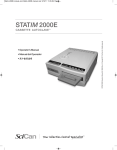
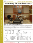
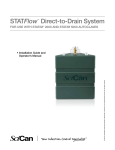
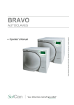
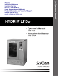
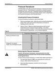
1
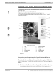
Mains Components
96-104748 Rev. 1.0
Mains Components
HAZARDOUS VOLTAGES ARE ACCESSIBLE ON THE POWER CORD,
POWER CORD RECEPTACLE, LINE FILTER, POWER SWITCH AND
POWER MAINS PORTION OF THE CONTROLLER BOARD WHEN THE
POWER IS ON. DISCONNECT THE POWER CORD BEFORE SERVICING.
STATIM L/5000/ 5000S UNITS CONTAIN ELECTRONIC CIRCUITRY WHICH
IS STATIC SENSITIVE. ALWAYS WEAR A STATIC STRAP WHEN WORKING WITH OR NEAR PRINTED WIRING BOARDS. IN ADDITION, USE
STATIC FOOTSTRAPS, GROUNDING MATS AND GROUNDED WORK
SURFACES WHEN SERVICING MICROPROCESSOR DEVICES, TRANSPORT BOARDS AND DEVICES IN STATIC PROTECTED BAGS.
REPLACE MAINS INPUT COMPONENTS WITH SCICAN APPROVED
PARTS ONLY, TO ENSURE ADHERENCE TO APPLICABLE
SAFETY AGENCY APPROVALS, STATE, PROVINCIAL, REGIONAL
AND NATIONAL LAWS.
Line Cords
STATIM L/5000/ 5000S detachable line cords plug into a panel mount A.C.
inlet receptacle in the back of the chassis.
Removing a Detachable Line Cord
To remove a detachable line cord (1) connected to the unit through a
panel mount A.C. inlet receptacle, follow these steps (see Figure 1):
1.
Turn the power switch (2) OFF, and unplug the power cord from the
wall outlet.
2.
Disconnect the line cord from the panel mount A.C. inlet receptacle (3).
Replacing a Detachable Line Cord
USE REPLACEMENT CORDS WITH APPROPRIATE SAFETY AGENCY
RATINGS AND APPROVALS ONLY.
To reinstall a detachable line cord (1), follow these steps (see Figure 1):
CONFIDENTIAL
1.
Select the appropriate replacement line cord from Spare Parts.
2.
The A.C. inlet receptacle (3) is keyed. Note the shape of the line
cord connector and the corresponding shape of the receptacle. Plug
in the connector.
3.
Plug the line cord into the wall receptacle and turn the power switch (3)
ON. Observe the LCD and indicator lights to determine that power is
present.
1
STATIM L/ STATIM 5000/ 5000S Cassette Autoclave Service Manual
96-104748 Rev. 1.0
Mains Components
3 or 4
1
1
3
2
1.
2.
3.
4.
detachable line cord
power switch
panel mount A.C.inlet receptacle
line filter
Figure 1
STATIM L/ STATIM 5000/ 5000S Cassette Autoclave Service Manual
2
CONFIDENTIAL
Mains Components
96-104748 Rev. 1.0
Removing and Replacing the A.C. Power Switch
To remove the power switch (2), follow these steps, (See Figure 2):
1.
Turn the power switch OFF, unplug the line cord from the wall outlet and
remove the detachable line cord (1) from the unit.
2.
Remove the four screws (5) holding the compressor bracket (6) to the
chassis (7) and rest the compressor to one side. Do not bend the
thermocouple leads (8). See, Compressor.
3.
Disconnect the leads from the A.C. inlet receptacle (3) or line filter (4) to
the power switch. Disconnect the white wire (9) from the upper spade
terminal, labelled 1, and the black (10) wire from the upper spade
terminal, labelled 2, nearest the pump (11).
4.
Disconnect the white wire (12) extending from Controller Board (13)
terminal J1-1 to the lower power switch spade terminal labelled 1a and
the black wire (14) extending from Controller Board terminal J1-2 to
the lower power switch spade terminal, labelled 2a, nearest the pump.
5.
The panel mount style switch is held into the panel with tabs.
Compress the tabs (15) and push the disconnected power switch out
of the chassis wall.
To replace the power switch (2), follow these steps, (See Figure 2):
CONFIDENTIAL
1.
From a position at the rear of the unit, orient spade terminals 1a and 2a
downwards and press the power switch into the clearance hole in the
chassis (7). Apply pressure evenly top and bottom until the bezel rests
against the chassis wall.
2.
Connect the white wire (12) extending from Controller Board (13)
terminal J1-1 to the lower right-hand power switch spade terminal
labelled 1a and the black (14) wire extending from Controller Board
terminal J1-2 to the lower left-hand power switch spade terminal,
labelled 2a.
3.
Connect the white wire (9) from the line filter (3) or the A.C. inlet
receptacle (4) to the upper right-hand power spade terminal
labelled 1, and the black wire (10) from either the attached power cord
or the A.C. inlet receptacle to the upper left-hand spade terminal
labelled 2, nearest the pump (11).
4.
Reinstall the compressor assembly (6) using the four screws (5)
retained from disassembly. Do not bend the thermocouple leads (7).
5.
A dielectric strength test (Hi-Pot) and a protective bonding
impedance test (ground continuity) must be performed on the
STATIM unit. See, Required Information, Tools and Routine
Maintenance.
3
STATIM L/ STATIM 5000/ 5000S Cassette Autoclave Service Manual
96-104748 Rev. 1.0
Mains Components
4
8
6
13
18
3
7
5
1.
12
14
17
16
detachable line cord(not
shown)
2. power switch
3. A.C. inlet receptacle
4. line filter
5. four screws (obscured)
6. compressor assembly
7. chassis
8. thermocouple leads
9. white wire
10. black wire
9
10
2
11
4
15
19
STATIM L/ STATIM 5000/ 5000S Cassette Autoclave Service Manual
4
11.
12.
13.
14.
15.
16.
17.
18.
19.
pump
white wire (J1-1)
Controller Board
black wire (J1-2)
power switch tabs
green wire
ground post
two screws
A.C. inlet receptacle
tabs
CONFIDENTIAL
Mains Components
96-104748 Rev. 1.0
5.
Plug the line cord into the wall receptacle and turn the power switch
ON. Observe the LCD and indicator lights to determine that power is
present.
Removing and Replacing the Line Filter
Some STATIM L/5000/ 5000S units contain a line filter which acts as a line
filter and a receptacle for the line cord. It is difficult to determine whether a
line filter has failed or not. If the unit blows mains fuses in the service panel
there may be a short in the line filter. Disconnect all leads from the mains
input and output and test for shorted circuits.
To remove a line filter (4), follow these steps,(See Figure 4):
1.
Turn the power switch (2) OFF, unplug the line cord from the wall outlet
and remove the detachable line cord from the unit. See, Removing a
Detachable Line Cord.
2.
Remove the four screws (5) holding the compressor assembly (6) to
the chassis (7) and rest the compressor to one side. Do not bend
the thermocouple leads (8). See, Compressor.
3.
Disconnect the white wire (9) from line filter position N, the black
wire (10) from line filter position P and the green wire (16) from line
filter position . If the pump (11) or pump tubing interferes with the
line filter terminals, move the pump or move/disconnect the
appropriate tube. See, STATIM L/5000/ 5000S Pumps.
4.
Remove two screws (17) holding the line filter to the chassis (7) and
remove the line filter.
To replace a line filter (4), follow these steps, (See Figure 4):
CONFIDENTIAL
1.
Insert the line filter in the opening in the chassis. The P and N faston
spade terminals are up, the ground terminal is facing down.
2.
Insert and tighten the two screws (18) holding the line filter.
3.
Connect the white wire (9) from the power switch to line filter position N
and the black wire (10) from the power switch to line filter position P.
4.
Connect the green wire (16) from the ground post (17) to line
filter position
.
5.
If the pump (11) or pump tubing was moved/disconnected, reinstall/
reconnect the pump/tube. See, STATIM L/5000 Pumps.
6.
Reinstall the compressor assembly (6) using the four screws (5)
retained from disassembly. Do not bend the thermocouple leads (7).
See, Compressor.
5
STATIM L/ STATIM 5000/ 5000S Cassette Autoclave Service Manual
96-104748 Rev. 1.0
Mains Components
6.
A dielectric strength test (Hi-Pot) and a protective bonding
impedance test (ground continuity) must be performed on the STATIM
unit. See, Required Information, Tools and Routine Maintenance.
7.
Plug the line cord into the wall receptacle and turn the power switch
ON. Observe the LCD and indicator lights to determine that power is
present.
Removing and Replacing the A.C. Inlet Receptacle
Some STATIM L/5000/ 5000S units contain an A.C. inlet receptacle for the
line cord.
To remove an A.C. inlet receptacle (3), follow these steps, (See Figure 4):
1.
Turn the power switch (2) OFF, unplug the line cord from the wall outlet
and remove the detachable line cord (1) from the unit. See, Removing a
Detachable Line Cord.
2.
Remove the four screws (5) holding the compressor bracket (6) to the
chassis (7) and rest the compressor to one side. Do not bend the
thermocouple leads (8). See, Compressor.
3.
Disconnect the white wire (9) from receptacle position N, the black
wire (10) from receptacle position L and the green wire (16) from
receptacle position .
4.
The A.C. inlet receptacle is a panel mount style component held into
the panel with tabs. Compress the tabs (19) and push the disconnected receptacle out of the chassis wall.
To replace an A.C. inlet receptacle (3), follow these steps, (See Figure 4):
1.
Insert and snap the receptacle into the opening in the chassis. The N
and L faston spade terminals are up, the ground terminal is facing down.
2.
Connect the white wire from the power switch to receptacle position N
and the black wire from the power switch to receptacle position L.
3.
Connect the green wire from the ground post to line filter position
4.
Reinstall the compressor assembly (6) using the four screws (5)
retained from disassembly. Do not bend the thermocouple leads (7).
See, Compressor.
6.
A dielectric strength test (Hi-Pot) and a protective bonding
impedance test (ground continuity) must be performed on the STATIM
unit. See, Required Information, Tools and Routine Maintenance.
7.
Plug the line cord into the wall receptacle and turn the power switch
ON. Observe the LCD and indicator lights to determine that power is
present.
STATIM L/ STATIM 5000/ 5000S Cassette Autoclave Service Manual
6
.
CONFIDENTIAL
96-104748 Rev. 1.0
Mains Components
Document Change Record
Document Number:
Title:
Mains Components
96-104748
REV.
1.0
DATE
99-01-23
DESCRIPTION OF CHANGES
New.
STATIM L/ STATIM 5000/ 5000S Cassette Autoclave Service Manual
ECO
99-0059
7
CONFIDENTIAL