1
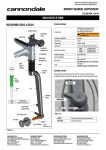
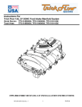
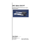
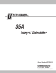
GenX® 255 Cylinder Heads for GM LS3 Thank you for purchasing Trick Flow GenX 255 aluminum cylinder heads for the GM LS3 and other GM LS series engines with a 4.000” or larger cylinder bore. Please follow the steps outlined in this instruction manual to ensure that the installation of your new cylinder heads is done correctly and that they perform according to design. Please read all of the enclosed information before beginning any work. If you have any questions regarding installation or the written materials supplied with your new heads, contact the Trick Flow technical department at 1-330-630-1555 for assistance, Monday through Friday from 9:00 am to 5:00 pm ET. Project Overview Recommended Tools Review all paperwork included in the installation packet Inspect the condition of all components Verify the part numbers and quantities of each product received (see Parts Checklist below) Mail the warranty card to Trick Flow Locate recommended tools Purchase any additional parts needed (See the Additional Parts Required section) Purchase the shop manual for your specific application, or take your vehicle to a qualified/certified mechanic Install the new cylinder heads Test drive and enjoy! Shop Manual for your vehicle Basic mechanics tool set (Metric sockets and combination wrenches) 0-100 ft.-lbs. torque wrench Torque angle meter Dial Calipers 0-8” Spark plug gauge Straightedge Feeler gauge Modeling clay Adjustable checking pushrod (TFS-9001) Solid setup roller lifter Parts Checklist Additional Parts Required You should have received the parts listed here. Please verify the part numbers and quantities of each component received. These components are required to complete the installation of your new GenX 255 cylinder heads. Please refer to the Recommended Components chart on the Technical Specifications sheet for specific part numbers. (1) (1) (1) (1) Assembled cylinder head Rocker arm rail (TFS-326LS3) Packet CMD Extreme Pressure Lube #3 Instruction packet If you are missing an item or a part was received in error, please contact Trick Flow at 1-330-630-1555, Monday through Friday from 9:00 am to 5:00 pm ET. TFS-DP-22 Rev. 3 Head gaskets Intake gaskets Exhaust gaskets Head bolts Intake bolts Exhaust bolts Moly lube Spark plugs Pushrods Rocker arms Thread sealer 07/1/15 Installation Instructions 1) Cylinder Head Removal Consult your shop manual for the proper cylinder head removal procedure for your vehicle. Taking notes, pictures, and even making a video of the disassembly will help you greatly when reinstalling brackets, routing hoses and electrical/sensor connections. 2) Prepping the Block With the old cylinder heads removed, inspect the cylinder bores for scratches, ridges, and cracks. If everything appears to be OK, put some paper towels in the cylinders to catch loose debris as the old head gaskets are scraped off the engine block’s deck surface. Remove all traces of the gaskets and any oil or grease that may be present by wiping the surface with brake cleaner. Check the deck surfaces for flatness by laying a straightedge across the deck lengthwise and sticking a .004" feeler gauge under it. If the feeler gauge fits anywhere under the straightedge, the block will need to be decked or head gasket failure will result. Once the block decks have been cleaned and checked, use the correct size tap to chase the threads in the head bolt holes. This will clean out old sealer and debris, which is extremely important for preventing leaks and torquing the heads down evenly on the block. After cleaning the head bolt hole threads, carefully remove the paper towels from the cylinders and discard. Using new paper towels clean the cylinders and coat the cylinder walls with a thin film of engine oil to protect them from corrosion. 3) Checking Exhaust Manifold/Header Clearance Place one of the GenX 255 cylinder heads on a suitable work stand and install the recommended spark plugs (refer to the Recommended Components chart on the Technical Specifications sheet for specific part numbers). Bolt the exhaust manifold/headers to the cylinder head and check for any interference. Repeat this procedure on the other cylinder head. A) Obtain the recommended adjustable pushrod length checker and a solid setup roller lifter that are identical in pushrod cup height to the fully extended hydraulic roller lifters that are going to be used permanently. B) Install setup roller lifter into cylinder #1 exhaust lifter bore with plastic lifter retainer, rotate the crankshaft until the roller of the lifter is on the base circle of the exhaust camshaft lobe as viewed through the lifter valley, pay close attention that the lifter is contacting the cam lobe, as the lifters tend to remain at lifted position in the plastic lifter retainer without valve spring force pushing on them. C) Temporary install (Do not torque!) your GenX 255 cylinder head onto the engine block with the head gasket to measure for new pushrod length. Install the adjustable pushrod length checker into the exhaust lifter/pushrod hole and install the rocker arm onto the Trick Flow rocker arm mount rail. Adjust the pushrod length checker so that the lifter roller is completely against the cam lobe and the rocker arm tip is in contact with the valve tip with zero lash and no preload in the assembly. D) Remove the pushrod length checker and measure the overall length. Once the setup length is determined, add 0.050”-0.075” to the overall length to account for lifter preload. The above preload dimensions are the same as 1 to 1½ turns of a M8 x 1.25 rocker arm bolt. 5) Checking Piston-To-Valve Clearance A) Once the proper pushrod length has been established, piston-to-valve clearance must be checked. This is an extremely important assembly step if using aftermarket pistons and/or high performance camshafts. Engine failure may occur from the valves contacting the pistons. B) Rotate the crankshaft until the engine is on the compression stroke of the #1 cylinder. Place a solid setup lifter in the lifter bore of the valve that you will be measuring. Be sure that the setup lifter is the same height as the lifters that will be installed in the engine permanently. C) Place a few 1/4” thick pieces of modeling clay across the upper half of the piston. Coat the clay with a very thin layer of new engine oil. Place the head gasket you will be using on the block and temporarily bolt the head on with five or six head bolts. NOTE: Cylinder heads with optional 6-bolt mounting pattern do not fit 2010 and later Chevrolet Camaro OEM exhaust manifolds; aftermarket headers are recommended. D) Install the Trick Flow rocker arm rail followed by the adjustable pushrod set to previous setup length. Tighten the rocker to zero lash, rotate the crankshaft at least twice, remove the cylinder head and gently remove the clay. 4) Determining Pushrod Length E) Carefully cut the clay into slices and look for the thinnest section of the valve impression. The impression is a 3D representation of the clearance between the piston and valve. Carefully measure the thickness of the clay with a machinist’s scale or calipers. The intake valve side of the clay should have .080" or more of clearance, and the exhaust should have .100" or more of clearance. Modify pistons as necessary. IMPORTANT NOTE: This step must be completed before heads are torqued to block. Trick Flow GenX® 255 Cylinder Heads for GM LS3 engines have been designed to use a 7.700” OAL or +0.300” longer than OEM pushrods. However, due to the multitude of parts combinations (Blocks, Head Gaskets, Camshafts, Lifters, and Rocker Arms), it is necessary to measure for proper pushrod length for your unique combinations of parts. For applications using hydraulic roller lifters and OEM nonadjustable rocker arms, follow the process below to determine pushrod length and lifter preload. For aftermarket adjustable rocker arms, follow manufactures instructions. TFS-DP-22 Rev. 3 NOTE: Reference the maximum recommended valve lift for the valve springs in the Technical Specifications sheet before purchasing an aftermarket camshaft. 07/1/15 6) Installing the GenX 255 Cylinder Heads With the block deck surfaces and cylinders clean and all checks completed, position the head gaskets on the block per the manufacturer’s markings. NOTE: Blow out the head bolt holes in the block with compressed air before installing the fasteners. Excess fluid at the bottom of the bolt holes can cause the engine block to crack when the bolts are torqued down. NOTE: Please be aware that pre-2004 blocks require longer head bolts than 2004 and up. Be sure to match your head bolts to the correct year block. Don’t be alarmed if some of the coolant holes in the block are restricted by a smaller hole in the gasket. This is done intentionally to regulate coolant flow. New OE type torque-to-yield cylinder head bolts must be installed during reassembly. For 2004 and after short style head bolts, torque the bolts in the four steps shown, following the sequence in Figure 1. For all other types of head bolts, follow service manual or manufacturer’s instructions. NOTE: If using aftermarket head bolts or stud kits for installation, follow the head bolt/stud manufacturer’s instructions for torque requirements. M8 Bolts 15 13 11 12 14 (15-14) 10 M11 Bolts 7 (1-10) 3 6 1 2 5 9 4 8 Figure 1 Stage One: Install all M11 bolts at 22 ft.-lbs. in sequence. Stage Two: Tighten M11 bolts 1-10 an additional 90 degrees in sequence. Stage Three: Tighten M11 bolts 1-10 an additional 70 degrees in sequence. Stage Four: Tighten M8 bolts 11-15 in sequence to 22 ft.-lbs. It is not necessary to re-torque TTY head bolts after initial break-in. 7) Installing the Valvetrain Consult your shop manual for the proper cylinder head valvetrain assembly procedure for your vehicle. Apply thread sealer to the threads of the intake rocker arm bolts during reassembly. IMPORTANT: DO NOT TORQUE YOUR ROCKER ARM BOLTS WHILE THE CAMSHAFT IS AT ANY LIFT. THE VALVE MUST BE ON THE BASE CIRCLE OF THE CAMSHAFT TO PREVENT PULLING THE ROCKER ARM THREADS OUT OF THE CASTING. NOTE: Trick Flow recommends using new LS3 rocker arms with upgraded bearings. Using rocker arms that have previously been installed can result in premature wear. TFS-DP-22 Rev. 3 Using the supplied CMD Extreme Pressure Lube #3, coat the top of the valve tips, the valve contact surface or roller on your rocker arms, and the pushrod cup in your rocker arm. NOTE: Assembled cylinder heads include new rocker arm rail mounts (TFS-326LS3) for use with LS3 1.7 ratio rocker arms with upgraded bearings. The OEM LS3 rocker arm rail mounts will not work with the GenX 255 heads. NOTE: If using aftermarket roller rocker arms, please be aware that the intake to exhaust rocker bolt centerlines need to be adjustable or specific to Trick Flow LS3 heads. Trick Flow GenX 255 cylinder heads have an intake to exhaust rocker bolt centerline of 2.155”. Your Trick Flow GenX 255 cylinder heads were designed to use the OEM length rocker arm bolts (52.5mm). Please be sure to check this length to avoid pulling the threads out of the head. NOTE: Rocker arm bolt threads protruding into the intake ports will not affect airflow results. 8) Reassembling the Rest of the Engine Install as many items as you can without putting the valve covers on. This will allow you to pre-lube the valvetrain, which is explained in the Pre-lubing the valvetrain section. 9) Pre-lubing the Valvetrain The valvetrain is now ready to be pre-lubed. Slowly pour a half quart of motor oil (per head) over the rocker arms, valve springs, and valve stems. Use an oil squirt can to get inside the valve spring and lube the valve stem and seal area. Reinstall the valve covers as soon as possible to keep contaminants out of the engine. DO NOT START THE ENGINE IF THE TOP HALF OF THE ENGINE HAS NOT BEEN PRELUBED! Finish reassembling all other components, brackets and vacuum lines. 10) Break-In and Tuning To ensure long life and trouble-free use, allow 2-4 hours of normal driving time before running the engine hard; this will break-in the valvetrain properly. NOTE: On pollution controlled motor vehicles, please consult the shop manual, for your specific vehicle, for tuning specifications. NOTE: For specific state emission inspection compliance, please affix the included label on or near the cylinder heads. Trick Flow Specialties®, Trick Flow®, TFS® and Twisted Wedge® are trademarks of Trick Flow Specialties, registered U.S. Pat. Off. Trick Flow GenX® 255 Cylinder Heads for GM LS are not a product of Chevrolet Motor Division, General Motors, nor are they endorsed by Chevrolet. Trick Flow Specialties is not affiliated with Chevrolet in any manner whatsoever. 07/1/15 Specifications Replacement Cylinder Heads Head Material: A-356 Aluminum TFS-3261B001-C01, Bare, each Comb. Chamber volume: 69cc (CNC profiled) TFS-3261B003-C01, Bare 6-bolt, each Intake port volume: 255cc Intake port dimensions: 2.550” x 1.250” LS3 square port Intake port location: Stock LS3 Intake valve diameter: 2.165" (TFS-32600211) Intake valve angle: 12° Intake valve length: 132.08mm Intake valve stem diameter: 8mm Exhaust valve diameter: 1.600" (TFS-32600212) Exhaust valve angle: 12° Exhaust valve length: 132.08mm Exhaust valve stem diameter: 8mm Valve guide material: Trick-Alloy powdered metal (TFS-30700252) Valve guide length: 2.100" Valve guide spacing: 4.400” TFS-32610001-C01, Cylinder Head, 255cc Intake Runner, 1.300” dual spring (370 lbs./in.), each TFS-32610002-C01, Cylinder Head, 255cc Intake Runner, 1.300” dual spring (463 lbs./in.), each TFS-3261T001-C01, Cylinder Head, 255cc Intake Runner, 1.300” dual spring (370 lbs./in.) with Titanium retainers, each TFS-3261T002-C01, Cylinder Head, 255cc Intake Runner, 1.300” dual spring (463 lbs./in.) with Titanium retainers, each TFS-3261T003-C01, Cylinder Head, 255cc Intake Runner, 1.300” dual spring (370 lbs./in.) with Titanium retainers, and 6bolt pattern, each TFS-3261T004-C01, Cylinder Head, 255cc Intake Runner, 1.300” dual spring (463 lbs./in.) with Titanium retainers and 6bolt pattern, each Valve seal: Viton Fluoroelastomer canister (TFS-30600455) Valve seat intake: Ductile Iron (TFS-51600271-1) Valve seat exhaust: Ductile Iron (TFS-30600272-1) Valve seat angles: 37°x 45°x 64° Intake; 37°x 45°x 60° Exhaust Valve spring pockets: 1.480" Valve spring cups: 1.300” OD Valve spring retainers: Chromemoly steel 7° x 1.500" OD, (TFS-21400410) Titanium 7° x 1.500" OD, (TFS-214T0415) Valve stem locks: 7° machined steel (TFS-30600444) Valve springs: Standard 1.300" O.D. dual spring (TFS-16904-16) 150 lbs. @ 1.800" installed height 400 lbs. @ 1.200" open 370 lbs. per inch rate 1.075” coil bind, .625" maximum lift (OE style rocker arms) Option 1 1.300" O.D. dual spring (TFS-16306-16) 155 lbs. @ 1.820" installed height 465 lbs. @ 1.200" open 463 lbs. per inch rate 1.100” coil bind, .650" maximum lift (roller rockers) Push rod length: Longer than stock required Rocker arm type: OEM LS3 with upgraded bearings or Aftermarket Roller Rockers with 2.155 intake/exhaust rocker bolt centers. CARB E.O Number: D-747 Viton® is a registered trademark of DuPont Performance Elastomers. Recommended Components Head gasket: TFS-30694060-045 MLS 4.060” bore, .045”thick TFS-30694060-051 MLS 4.060” bore, .051”thick Ultimate Bolt-On Performance Lifetime Warranty Trick Flow Specialties cylinder head castings are backed by a lifetime warranty. If a cylinder head casting fails to provide the original purchaser with complete satisfaction, Trick Flow Specialties will repair or replace it free of charge — guaranteed! Moreover, the valves, valve guides, valve seats, valve job, valve springs, valve spring retainers, valve locks, rocker arm studs, guideplates, and valve stem seals included on assembled Trick Flow Specialties cylinder heads are warranted to the original purchaser to be free from defects in materials and workmanship for a period of two years from the date of purchase. All other Trick Flow Specialties products are warranted to be free from defects in materials and workmanship for a period of 90 days. There are no mileage limitations. Extent of Warranty Customers who believe they have a defective product should return it to the dealer from which they purchased or ship it freight prepaid to Trick Flow Specialties along with proof of purchase and a complete description of the problem. If a thorough inspection indicates defects in materials or workmanship, our sole obligation is to repair or replace the product. This warranty is only if the product is properly installed, subjected to normal use and service, did not fail due to owner negligence or misuse, and has not been altered or modified. Trick Flow Specialties warranties do not cover any installation or removal costs. Trick Flow Specialties is not liable for consequential damages for breach of contract of any warranty in excess of the purchase price of the product sold. Exhaust gasket: GM 12558573 Head bolts/studs: Pre-2004 blocks TTY OEM style bolts TFS-92010 ARP 234-4316, 12 pt. stud kit 2004+ blocks TTY OEM style bolts TFS-92011 ARP 234-4317, 12 pt. stud kit Pistons: OEM Rocker arms: OEM LS3 with upgraded bearings (.625” recommended maximum lift) PROPOSITION 65 WARNING This product may contain one or more substances or chemicals known to the state of California to cause cancer, birth defects or other reproductive harm. Trick Flow Specialties 285 West Avenue Tallmadge, Ohio 44278 Sales: (330) 630-1555, Fax: (330)630-5565 Web: Trickflow.com Spark plugs: NGK-4177 Valve Cover Spacers: TFS-3060800, .500” height Rocker Arm Bearing Upgrade Kit: SME-143002 Coolant Sensor plug: TFS-30600615 (M12 x 1.5 thread) Hydraulic Roller Lifters: TFS-21400002-16 TFS-DP-22 Rev. 3 07/1/15