1
.~.
MANUAL FOR CODED-WIRE TAGGING. AND
FIN CLIPPING OF JUVENILE SALMONIDS AT
ENHANCEMENT OPERATIONS FACILITIES
July 1990
by
T. L. Nichols and J.E. Hillaby
Fisheries and Oceans Canada"
Pacific Region,
555 West Hastings Street,
Vancouver, B.C.
V6B SG3
• Prepared under contract #90SB.FP501-7-0060/A to Supply and Services Canada by
Streamline Consulting Services Limited, P.O. Box 880, Ladysmith, B.C. VOR 2EO.
ii
TABLE OF CONTENTS
LIST OF FIGURES.
iv
LIST OF TABLES •
iv
LIST OF APPENDICES.
v
FOREWORD
vi
INTRODUCTION
FISHERY OBJECTIVES - CODED-WIRE TAGGING
FISHERY OBJECTIVES - FIN CLIPPING
1
1
2
METHODOLOGY •
2
WHAT DO I NEED BEFORE I START?
1.
.
PERSONNEL • • • •
Team Organization
Job Descriptions
2.
CONDITION OF FISH • . •
4
4
Water Temperature
Fish Size . . . .
Disease Treatment
5
12
12
Smolting Fish
3.
3
3
3
EQUIPMENT • . • . .
Tagging Machines
13
13
Scissors
14
HOW DO I DO IT?
1.
PREPARE THE FISH
15
15
15
Starving Fish •
Containing Fish
2.
PREPARE THE AREA
Tagging Area
Inflow Water Quality
Equipment Set-up
3.
PREPARE THE MACHINES
Unit Assembly .
Machine Preparation
4.
CHOOSE THE ANAESTHETIC
2-Phenoxyethanol
MS-222 (Tricane methanesulfonate)
Marinal . . . •
Carbon Dioxide
"
17
17
17
17
21
21
22
23
23
24
24
24
(
iii
Recommendations on the Choice of the Anaesthetic
. Human Health Hazards
25
25
5.
CODED-WIRE TAGGING
Basic Operations
Establishing Fish Size Ranges
Tag Positioning .
Handling Rejects
Other •
26
26
26
27
30
31
6.
FIN CLIPPING
Hand Movement
31
31
"
WHAT SHOULD I BE LOOKING FOR?
,
1.
QUALITY CONTROL CHECKS - GENERAL
34
2.
CODED-WIRE TAGGING
Tag Retention
35
35
3.
ADIPOSE FIN CLIPPING
Clip Checking .
Determination of Good and Poor Adipose Clips
Adipose Fin Regeneration
Other Concerns
38
38
38
38
40
4.
VENTRAL FIN CLIPPING
Responsibilities
container System
Frequency of Checks
Count Checks
Visibility of the Ventral Fin Clip Area
Determination of Good and Poor Ventral Clips
Fin Regeneration
40
40
40
41
41
41
42
43
5.
MORTALITY
Acceptable Mortality Level
Anaesthetic Mis-use
Deep Clips • . . •
Poor Water Quality
Other Factors • . •
44
44
44
45
45
46
.
6.
SPEED AND EFFICIENCY STANDARDS
47
7.
DATA RECORDING
48
(
TAGGING MACHINE ·TROUBLESHooTING
1.
CLEANING AND. MAINTENANCE
Frequency of Cleaning
Cleaning Procedure
49
49
49
(
iv
2.
TAG INJECTOR
Tag Injector Jamming
Poor Wire Feed
51
51
54
54
54
55
55
No Power
Poor Cycling
Head Mutilation
Improper Tag Length
3.
QUALITY CONTROL DEVICE (QCD)
Gain Setting
Delay Setting
No Water Jets
pitch Setting
55
56
56
57
57
4.
CUTTERS • .
Selecting an Edge
Recording Number of Cuts
57
57
57
Cutter Maintenance
58
KEY RECOMMENDATIONS • • . • . •
CODED-WIRE TAGGING
FIN CLIPPING
CODED-WIRE TAGGING AND FIN CLIPPING
61
61
61
62
ACKNOWLEDGEMENTS
62
REFERENCES
63
LIST OF FIGURES
1.
Tagging table set-up for two machines .
19
2.
Tagging table set-up for three machines
20
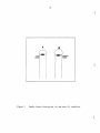
3.
Proper and improper coded-wire tag placement.
4.
Holding and clipping the adipose fin, prior to coded-wire
tagging
•.•..•..•.••
32
5.
Acceptable and unacceptable adipose fin clips.
33
6.
Coded-wire tag injector mechanism showing push arm assembly
and single arm action
50
7.
Needle funnel showing new and worn condition.
52
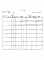
8.
Proposed record sheet for cutter use and maintenance.
59
.
28
LIST OF TABLES
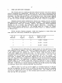
1.
Comparison of maximum water temperatures for marking at the
surveyed hatcheries .
. . . . • . . . . . . . . .
6
(
v
2.
Chinook sizes for coded-wire tagging at the surveyed hatcheries
7
3.
Coho sizes for coded-wire tagging at the surveyed hatcheries.
9
4.
Chum sizes for coded-wire tagging at the surveyed hatcheries.
11
5.
Comparison of numbers of scissors used and replacement rates at the
6.
7.
surveyed hatcheries, as determined from questionnaire returns
16
Comparison of tag loss and fish mortality rates considered
acceptable at the surveyed hatcheries • •
• . • . • .
39
Comparison of numbers of machines, cutters, cutter use and machine
downtime at th~ surveyed hatcheries, as determined from
questionnaire returns . . . . . . . . . . . . . . . . . . . . . . .
60
LIST OF APPENDICES.
A.
Northwest Marine Technology Instruction Manual for Tagging
unit Models MKII and MKIII
B.
Northwest Marine Technology Instruction Manual for Tagging Unit
Model MKIV
C.
Construction Details for a TWO-Machine Tagging Table
D.
Fin Clipping Table Design Criteria
E.
Summary of Questionnaire Responses
F.
Proposed Data Record Sheets for Coded-Wire Tagging and Fin
Clipping
G.
Northwest Marine Technology Technical Bulletins
(
(
vi
FOREWORD
by D.D. Bailey
With the rapid expansion of hatchery facilities as a result of the Salmonid
Enhancement Program, there were no specific guidelines to ensure high quality
and consistent marking at all facilities.
Procedures were passed on by the
staff from the more established facilities and by contract marking with a few
contractors who had specialized in this area. Written guidelines were scarce
but those that existed, including Bams (1979) gUidelines for fin clipping quality
and the Alaska Department of Fish and Game Manual (Moberly et al. MS 1977), were
being used. Procedures and gUidelines varied among facilities, and adult returns
began to show a wide variation in mark quality that was reflected in the relative
percentage of good marks and tag loss rates.
In 1986 the incidence of
regeneration on ventral clipped chum salmon caught in the Nitinat commercial
fishery was very high resulting in low hatchery contribution estimates based on
marks recovered.
If hatchery output marking was to provide a basis for
estimating hatchery contribution and corresponding fishery management, it was
clear that procedures and quality control must be both standardized and improved.
As a result, the Bioprogram Coordinator Division awarded a marking
evaluation contract to provide advice and guidelines for the improvement of
quality of marking programs at Enhancement Operations facilities. The evaluation
was to be conducted through a review of available information and on-site
observations. The contract work was conducted between July 1, 1987 and December
31, 1988 and included the design and distribution of a marking questionnaire to
evaluate the procedures used at Enhancement Operations facilities.
From the
results of this questionnaire, hatcheries were selected for visitation by the
contractor and in some cases the Scientific Authority. Hatcheries were selected
based on species, geographic location, fin clipping versus coded-wire tagging,
established versus new facilities, degree of hatchery involvement in marking,
"good" and "problem" hatcheries, and visitation opportunity.
Results and
concerns were discussed with the hatchery manager during the visit and followed
up by a written evaluation by the contractor to the Scientific Authority. The
result of the visits, questionnaires, literature search, and the contractor's
(T. Nichols) personal experience have been detailed in this marking manual. In
addition, the contractor has included within this manual the results of the
Tagging Machine Maintenance Workshop held April 27, 1988, as was previously
agreed with the Scientific Authority and the workshop organizers (Shary Stevens
and Pete Campbell).
This manual is a revised version of a draft which was distributed to
hatchery staff for comment. It is hoped that additional discussion can result
on marking quality gUidelines, and that these are applied consistently throughout
all hatcheries. It is hoped that individual hatcheries will add sections unique
to their own particular situations as well as recommendations to ensure high
quality marking at all facilities. This publication will hopefully evolve into
a comprehensive marking manual for use at all facilities.
1
IN:r'RODUCTION
The purpose of this report is to describe the best practical methods for
coded-wire tagging and adipose and ventral fin clipping. These types of marks
are used to identify the vast majority of marked Pacific salmon stocks. Marked
salmon recoveries form the basis of commercial and sport salmon fishery
management, hatchery production strategies, experimental design and international
negotiations. It is critical that marking be performed with precision and care
so that mark mortality, fin regeneration and tag loss rates'are minimized. To
achieve this goal, marking equipment and crews must be efficiently organized and
managed.
There is some evidence that current juvenile fish handling and marking
procedures are not providing adequate recovery data from adult fish.
Surveys
showed that from 10% to 15% of adipose clipped salmon in the Mark Recovery
Program did not contain coded-wire tags, while in one test, approximately 75%
of adult fish with "stubby" adipose fins did contain coded-wire tags (J. Thomas,
J.O. Thomas and Associates, Vancouver, pers. comm.). Furthermore, of the chum
ventral fin clip marks recovered in the Nitinat fishery in 1986, approximately
25 had regenerated to at least 25% of full size and a further 24 marks
regenerated to 50% of full size (MacKenzie MS 1987). Clearly, controlling tag
loss and fin regeneration is paramount to the success of the marking program.
FISHERY OBJECTIVES - CODED-WIRE TAGGING
Coded-wire tag data from surviving adult salmon have a variety of uses.
Coded-wire tags provide tangible evidence that catchable adult fish were produced
by a given hatchery, thereby demonstrating effective fish production.
Tag
recovery data are also expanded statistically to derive survival rates from
release to adult capture and to adult recovery on spawning grounds, so that
different production strategies and/or experimental groups can be compared.
Furthermore, since coded-wire tags identify a mix of stocks within a fishery,
harvest managers are able to examine the run timing and harvest rates of
different stocks and develop improved harvest strategies.
Ensuring that fish are tagged effectively is an essential part of this
information system.
When a tagged fish is recovered, expansion factors are
applied to estimate the proportion of tagged fish within the surveyed population,
and subsequently the tagged proportion wi thin the unsurveyed population of
captured fish.
Different expansion factors are applied to the commercial and
sport fleet" as survey patterns permit. Depending on the application of the
data, several mUltipliers can be used so that one tag recovery may represent
many more that may be present in the catch. Regenerated adipose fins and/or high
rates of tag loss can confound the recovery system and render much of the data
useless.
In most cases, economics demand that only a portion of the hatchery's
output be tagged. Unless special experimental groups are present, the tagged
fish must represent the entire hatchery production group.
It is therefore
imperative that the marking crew organize a non-selective operation.
Accordingly, there should be no pre-tagging selection for "optimum" fish size,
condition or timing pattern among the tazged group only.
(
2
Sufficient numbers of fish should be tagged to ensure that, given expected
survival rates, enough tags will be recovered to provide a statistically reliable
data base for resource managers. Most hatcheries mark a minimum of 75,000 fed
chum fry, 75,000 coho fry, 50,000 juvenile chinook, and 10,000 coho smolts.
Some hatcheries may mark more fish to compensate for lower survival rates that
are inherent at upriver production sites (e.g. Quesnel Hatchery), or are the
result of smaller size at release (e.g. chum tagging) or expected overwinter
mortalities (e.g. coho tagging for later release). In addition, multiple tag
codes can be used on large groups of fish to determine statistical variation in
survival among identical groups and to evaluate different experimental groups
within a hatchery population.
FISHERY OBJECTIVES - FIN CLIPPING
Adipose and ventral fin clipping is often used as a way of marking
anadromous fish where fish size is too small and where the cost is too high for
coded-wire tagging; this applies especially to pink and chum fry. Note, however,
that Alaskan agencies tag these fry at 0.75 g and smaller (J. Kallshian,
Northwest Marine Technology, pers. comm.). Since only a few fin clip codes are
available (ventral, adipose, maxillary bone), most of the fin clipping performed
by the Department of Fisheries and Oceans (DFO) is used for distinguishing
between hatchery and non-hatchery fish in target fisheries. Examples of this
strategy are chum marking at Pallant, Conuma and Snootli hatcheries.
(
Fin clipping is also used in freshwater studies to examine populations and
compare stocks. For example, Hurst and Blackman (1988) used fin clips to assess
coho fry outplanting into various habitat types, both barren and containing
indigenous (unmarked) fish, and to compare the freshwater behaviour of hatchery
and non-hatchery stocks. Ocean distribution was not a primary concern in these
studies. Clipped juveniles were identified visually and returned live to the
system.
Since the DFO uses adipose and ventral fin clips almost exclusively in fin
clipping operations, this report does not discuss maxillary, half dorsal or other
fin clips that may be applied for experimental purposes.
METHODOLOGY
This manual presents field techniques developed to improve marking quality
and efficiency. The manual is based on personal experience, on- site evaluations,
interviews with numerous technical authorities and questionnaire responses. The
practical work for this manual was conducted by T.L. Nichols and all references
to "the author" in the following pages refer to that particular author.
It is expected that not everyone will agree with the contents of the
manual, since the best technical advice possible is necessarily judgemental.
The benefits from using this manual will differ as well.
Some locations may
achieve the utmost in quality marking with only slight modifications from the
present system. Others may want to revise completely their current operation
to achieve this goal. We believe that even extensive changes are well worth the
effort.
(
3
WHAT DO I NEED BEFORE I START?
1.
PERSONNEL
Fish tagging is performed using an assembly-line system, including one,
two or three tagging machines and a crew complement of taggers, fin clippers and
supervisors. The operation should be continuous throughout the day and proceed
consistently for days or weeks until all the fish are marked.
In personnel
terms, it is important to ensure that the team is appropriately organized, that
everyone is well trained and directed, and that sufficient supervision is
provided to ensure adequate quality control and operational efficiency.
Team Organization
Each site potentially has a different team organization based on different
methods of hiring workers and assigning responsibilities. Where a contractor.
is retained, a tagging supervisor from the hatchery should be in charge since·
the tagging crew does not report to the hatchery manager. It is critical that
the tagging supervisor closely communicate with the hatchery management, not only
to enSure that the marking quality and numbers are achieved, but to coordinate
the tagging rate with strategies for starving and holding the fish to be marked.
In this way, the tagging and hatchery components can be coordinated to ensure
a smoothly run operation.
For coded-wire tagging, the ratio of clippers to taggers should be 2:1,
or two clippers for every tagger. Therefore, if three tagging machines are used,
six clippers are required.
The importance of a 2: 1 ratio is based on the
effieient use of the taggers' time and also ensures that the clippers have
sufficient time to maintain quality clips.
If the ratio is 1:1, the clipper
cannot maintain pace with the tagger. Either the clipper must speed up, in which
case fin clip quality suffers, or the tagger must slow down. At one hatchery
where a 1:1 strategy was used, an incidence of 75% poor clips and a marking rate
of only 12,000-13,000 fish/day was reported for a two-machine set-up, which is
at least 4-5,000 below the average rate obtained with a 2:1 clipper/tagger ratio
using a similar set-up.
Personnel requirements for fin clipping operations do not differ greatly
from those required for coded-wire tagging, except that fin clipping operations
are more loosely organized since no need exists to coordinate with machine
speeds. It is important, however, that all new personnel be trained properly,
and that each clipper be taught the proper technique. It will be expected that
during the first few days of training, the clipping speed will be below average,
but it will increase with time. Clipping quality can be controlled with good
supervision so that the only variable between·crews should be clipping speed as
related to previous clipping experience.
Job Descriptions
Taggers: Taggers should be experienced. They must be able to handle fish
properly, and recognize correct machine operation and correct tag placement.
When training new taggers, higher tag loss and higher mortalities. should be
expected.
(
4
Clippers: Clippers must be able to handle fish carefully, clip the fin
properly and size-sort the clipped fish. It is not mandatory that fin clippers
be experienced at the start of the operation. They can be trained in one hour
to make a quality clip. Those unable to do so, probably lack sufficient manual
dexterity and should be replaced at the end of the day.
Speed should not be
encouraged until high quality clips are regularly obtained. Once this occurs,
speed will increase naturally, usually without a loss in clip quality.
Supervisor: The supervisor must ensure that 1) the tagging operation is
properly planned and organized, 2) the equipment and fish are ready for tagging,
3) the personnel are adequately trained and monitored, 4) the quality control
standards are effectively and consistently in place, and S) the data are
collected in an orderly manner.
2.
CONDITION OF FISH
The most important aspect of preparing fish for coded-wire tagging is
establishing the seasonal timing of the tagging activities.
Tagging usually
takes place from late February to early July, with the exception of overwintered
coho which may be tagged in mid-winter.
Preparing fish for fin clipping is
similar to preparing them for coded-wire tagging, except that much smaller fish
can be fin clipped.
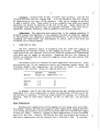
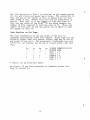
The primary factors to consider are water temperature and fish size.
Since
(.
each hatchery has its own temperature regime and subsequent growth curves, the
following weights and temperatures are provided to assist
appropriate site-specific timing for tagging operations.
Species
Chinook
Coho
Chum
Minimum
Weight (g)
1.0
1.0
0.8
Maximum
Temperature
in estimating
<' C)
14
15
14
In general, even if the fish size criteria are met, marking should not be
undertaken if 1) water temperature is above the determined critical level for
the hatchery in question, 2) fish are being treated for disease, or 3) fish are
smolting. Each of these major concerns, as well as fish size, are discussed
below.
Water Temperature
Maximum water temperatures during tagging can vary among sites and stocks.
For example, Hartley Bay fish were tagged at water temperatures ranging from 20'C
to 2S'C with approximately 10 mortalities reported each year (100,000 coho tagged
in each of 3 years). Normally, tagging at these temperatures at other locations
would kill the fish. However, the Hartley Bay fish are hatched and reared at
high water temperatures and are released into a warm-water lake. In contrast,
(
5
chinook at Quesnel Hatchery are reared in cold water and have a maximum tagging
temperature of only approximately l2'C. At more southerly hatcheries it may be
possible to tag chinook safely at l5'C or 16'C. Therefore, each hatchery should
conduct its own experiments to determine the critical temperature for tagging
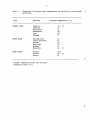
under site-specific ·conditions (Table 1).
When determining the critical temperature for each site and species, it
is important to assess the past history of tagging operations to determine the
actual temperatures at marking, the mortalities at that time, and whether or not
differences in the daily mortalities coincided with even a slight change in
temperature.
If it becomes necessary to tag fish at water temperatures higher than the
considered maximum, it is especially important not to clip too deep. as this
will guarantee fungus growth on the fish. Furthermore, the hatchery management
should consider increasing the numbers of fish tagged in order to compensate for
expected higher than normal mortalities.
In locations and at times of the year when warm water temperatures may
create handling and tagging problems, variation in the daily timing of tagging
may help avoid working in the heat of the day. For example, tagging shifts from
5:00 am to 11:00 am and from 6:00 pm to 8:00 pm daily, or from 6:00 am to 2:00
pm could take advantage of cooler daily air and water temperatures. The primary
problem with this scheduling is that government hatchery crews work from 8:00 am
to 4: 00 pm so that a special effort would be required to coordinate the different
shifts of hatchery and marking crews. Often a 6:00 am to 2:00 pm shift works
well; the tagging crew gets a 2 - hour head start on the regular hatchery
activities, and when they leave for the day, the hatchery crew has a few hours
to inspect the tagged fish and move untagged fish into containers prior to the
next day's marking.
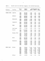
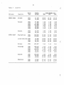
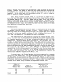
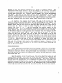
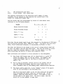
Fish Size
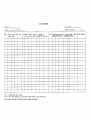
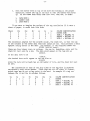
Tables 2, 3 and 4 provide an overview of the coded-wire tagging programs
for chinook, coho and chum respectively, at the surveyed hatcheries. Annual mean
sizes at tagging ranged widely for chinook (0.8-14.8 g) and coho (1.6-30.0 g)
but not chum (0.9-1.8 g).
For scheduling purposes, a 2.5 g average size is considered optimal for
tagging, as the fish are relatively uniform and at a convenient size for handling
and grading. At this size, two tagging machines can be set up to obtain optimal
tag placement, one machine covering the 1.8 - 2.5 g size range, and the other
the 2.5 - 4.0 g size range. Note that fish tagged at a larger size (e.g. 6 g
average) will show a larger size variation (1-12 g) and consequently will require
more grading and nose-mold adjustments.
This will make it more difficult to
obtain good tag placement. Tagging scheduling should include getting the fish
to an optimum tagging size of 2.5 g in such a way as to coincide with natural
migration and any other timing factors that the hatchery is considering.
6
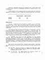
Table 1.
comparison of maximum water temperatures for marking at the surveyed
hatcheries.
Area
FRASER RIVER
SOUTH COAST
NORTH COAST
Hatchery
Maximum Temperature
14
12
-
15
-
13
Capilano
Chehalis
Chilliwack
Clearwater
Inch
Shuswap
9'
Big Qualicum
Little Qualicum
Nitinat
Puntledge
Quinsam
Robertson
15
14
10
16
14
12
Kitimat
Pallant
Snootli
<12'
12 - 13
12
(
(
• C)
11
14
13'
(
, Highest temperature that has occurred.
, Preferably below 10·C.
(
7
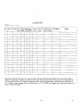
Table 2.
Chinook sizes for coded-wire tagging at the surveyed hatcheries.
Brood
Year
Number
Marked
Capilano
1984
1985
1986
502,090
126,399
170,998
8.00
8.00
8.00
2.50
2.50
1.80
5.25
5.25
4.90
Chehalis
1984
1985
1986
150,000
200,000
200,000
1.00
0.80
2.00
1.00
0.80
1.00
1:00
0.80
1. 50
Chilliwack
1984
1985
1986
92,000
200,000
165,000
8.00
10.00
10.00
4.00
3.00
4.00
6.00
6.50
7.00
Clearwater
1984
1985
1986
260,000
377,000
359,000
4.00
4.00
4.00
3.00
3.00
3.00
3.50
3.50
3.50
Eagle
1984
1985
1986
457,000
359,000
360,000
3.40
3.50
2.60
3.20
3.40
2.10
3.30
3.45
2.35
Inch Creek
1986
47,538
6.00
6.00
6.00
Quesnel
1984
1985
1986
1,123,000
970,000
850,000
2.50
2.00
3.20
2.50
2.00
2.10
2.50
2.00
2.65
Shuswap Falls
1984
1985
1985
1986
1986
103,500
84,200
84,500
102,064
52,786
5.00
4.00
5.00
3.03
3.77
3.50
2.40
3.00
3.03
3.77
4.25
3.20
4.00
3.03
3.77
Spius
1984
1985
1986
267,000
285,000
350,000
4.00
4.00
5.00
4.00
3.00
3.50
4.00
3.50
4.25
Tenderfoot
1984
1984
1985
1985
1986
1986
90,000
112,000
90,000
91,000
98,000
90,000
2.00
4.00
2.00
4.00
4.00
3.00
2.00
1.00
2.00
1.00
1.00
3.00
2.00
2.50
2.00
2.50
2.50
3.00
Kitimat
1984
1984
1984
1985
1985
1985
1986
1986
1986
98,715
49,765
49,445
79,698
79,900
50,661
78,784
79,078
53,438
11.10
8.30
9.30
11.20
10.20
7.80
10.50
9.70
8.80
10.20
8.30
9.30
11.20
10.20
7.80
10.50
7.40
8.80
10.65
8.30
9.30
11.20
10.20
7.80
10.50
8.55
8.80
Pallant
1986
40,000
2.50
2.50
2.50
Division
Facility
FRASER RIVER
NORTH COAST
Chinook Weight ( g)
Max.
Min.
Avg.
8
Table 2
(
(cont'd.)
Division
SOUTH COAST
Chinook Wei~ht ( ~l
Max.
Min.
Avg.
Brood
Year
Number
Marked
Snoot1i
1984
1984
1985
1985
1986
1986
80,731
203,148
76,145
208,402
50,453
209,006
1.80
2.90
1. 80
2.90
1. 80
2.90
1.50
2.00
1. 50
2.00
1.50
2.00
1. 65
2.45
1. 65
2.45
1. 65
2.45
Big Qualicum
1984
1985
1986
254,000
260,000
216,000
3.00
3.00
3.00
6.00
6.00
6.00
4.50
4.50
4.50
Chernainus
1984
1985
1986
78,630
75,610
80,307
4.50
5.50
4.50
4.50
5.50
4.50
4.50
5.50
4.50
Little Qualicum 1984
1985
1986
80,000
76,000
75,000
4.00
4.00
4.00
3.50
3.50
3.50
3.75
3.75
3.75
Nitinat
1984
1984
1984
1985
1985
1985
1985
1985
1986
1986
37,464
37,900
36,699
26,557
26,324
26,737
26,24.9
27,713
52,940
52,942
2.54
2.73
2.80
2.17
2.19
2.37
2.88
3.00
3.95
4.00
2.54
2.73
2.80
2.17
2.19
2.37
2.88
3.00
3.95
4.00
2.54
2.73
2.80
2.17
2.19
2.37
2.88
3.00
3.95
4.00
Puntledge
1984
1985
1986
166,689
646,291
336,441
5.50
5.50
5.50
5.50
5.50
5.50
5.50
5.50
5.50
Quinsarn
1984
1984
1985
1985
1985
1986
128,000
227,000
25,000
48,000
181,000
179,000
3.10
14.00
3.00
10.30
14.80
8.34
3.10
14.00
3.00
10.30
14.80
8.34
3.10
14.00
3.00
10.30
14.80
8.34
Robertson
1984
1985
1986
263,523
211,823
393,705
2.31
3.28
2.93
2.31
3.28
2.93
2.31
3.28
2.93
Facility
(
(
9
Table 3.
Coho sizes for coded-wire tagging at the surveyed hatcheries.
( III
Brood
Year
Number
Marked
Max.
Capilano
1984
1985
236,620
132,469
20.00
20.00
10.00
10.00
15.00
15.00
Chehalis
1984
1985
1986
80,000
50,000
50,000
9.00
8.00
10.00
6.00
7.00
8.00
7.50
7.50
9.00
Chilliwack
1984
145,000
15.00
12.00
13.50
Clearwater
1984
1985
1986
122,000
130,000
108,000
4.00
4.00
4.00
3.00
3.00
3.00
3.50
3.50
3.50
Eagle
1984
1985
1986
342,000
337,000
332,000
2.20
2.40
1. 80
1. 80
2.10
1. 70
2.00
2.25
1. 75
Inch Creek
1984
1984
1984
1984
1984
1985
1985
1985
1985
1985
1985
40,102
10,080
9,994
10,200
10,016
20,073
9,367
10,158
10,073
9,895
10,089
19.00
20.00
17.00
17.00
17.50
16.00
17.00
14.00
14.00
13.00
16.00
17.00
20.00
17.00
17.00
17.50
16.00
17.00
14.00
14.00
13.00
16.00
18.00
20.00
17.00
17.00
17.50
16.00
17.00
14.00
14.00
13.00
16.00
Quesnel
1985
1986
20,000
30,000
2.50
4.00
2.50
4.00
2.50
4.00
Spius
1984
1985
1986
51,000
140,000
150,000
2.00
4.00
4.00
2.00
3.00
2.50
2.00
3.50
3.25
Tenderfoot
1984
1985
1986
44,000
69,000
Unknown
20.00
20.00
20.00
20.00
20.00
20.00
20.00
20.00
20.00
Division
Facility
FRASER RIVER
Coho Weillht
Min.
Avg.
10
Table 3
(cont'd.)
Brood
Year
Number
Marked
Max.
Kitimat
1984
1985
47,209
70,924
20.40
21. 70
18.10
20.00
19.25
20.85
Pa11ant
1984
1985
1985
1986
1986.
1986
97,000
31,000
156,000
31,000
61,000
94,000
1.60
1.60
1. 90
3.50
1. 70
2.50
1. 60
1. 60
1. 90
3.50
1. 70
2.50
1.60
1.60
1. 90
3.50
1. 70
2.50
Snootli
1985
1986
20,919
50,216
3.00
2.70
3.00
2.70
3.00
2.70
Big Qualicum
1984
1985
160,000
120,000
14.00
14.00
14.00
14.00
14.00
14.00
Little Qualicum 1984
1985
1986
16,200
1f. , 350
20,550
20.00
20.00
20.00
20.00
20.00
20.00
20.00
20.00
20.00
Division
Facility
NORTH COAST
SOUTH COAST
(
Coho Weight ( gl
Min.
Avg.
Nitinat
1986
103,607
3.41
3.41
3.41
Puntledge
1984
1984
1985
1985
1986
1'00,076
40,000
166,016
58,145
21,013
2.26
17.00
4.00
13.46
2.25
2.26
17.00
4.00
13 .46
2.25
2.26
17.00
4.00
13 .46
2.25
Quinsam
1984
1984
1985
100,000
81,000
43,000
6.80
30.00
25.00
6.80
30.00
25.00
6.80
30.00
25.00
Robertson
1984
1985
47,940
43,581
13.10
11.70
13.10
11.70
13.10
11.70
(
(
11
Table 4.
Chum sizes for coded-wire tagging at the surveyed hatcheries.
Brood
Year
Number
Marked
Max.
Chehalis
1984
1985
1986
230,000
150,000
80,000
0.95
0.95
0.95
0.75
0.75
0.75
0.85
0.85
0.85
Inch Creek
1985
1985
1986
103,811
34,340
151,724
1.10
0.95
1.25
0.95
0.95
1.00
1.03
0.95
1.13
Kitimat
1985
36,062
1.40
1.40
1.40
Pallant
1984
1984
1984
1985
1986
35,000
76,000
38,000
133,000
87,000
1. 70
1.40
1.00
1. 70
1. 80
1. 70
1.40
1.00
1. 70
1. 80
1. 70
1.40
1.00
1. 70
1.80
Punt1edge
1984
1985
1986
154,080
104,097
55,632
1.00
1.00
1.00
1.00
1.00
1. 00
1.00
1. 00
1.00
Division
Facility
FRASER RIVER
NORTH COAST
SOUTH COAST
Chum Weight ( g)
Min.
Avg.
(
12
Although fish can be tagged at a minimum size of about 1 g, long-term tag
retention will be lower on smaller fish. For example, although the 24-hour tag
loss is comparable between 1 g fish and larger juveniles, the long-term tag loss
among returning adults is considerably higher among the smaller tagged fish (up
to 20% compared to· the normal level of 15%). Therefore, in order to maximize
long-term tag retention, it is recommended not to tag below 1.8 g for chinook
and coho.
Reaching the minimum size of 0.8 g can be a problem for chum salmon, as
chum fry are frequently released before they reach this size. Often, when chum
are held until the tagging size is reached, they begin to smolt which may
prohibit their marking. One effective strategy used at the Pallant Hatchery,
consists of holding chum fry in seapens until tagging, then transferring them
to fresh water for coded-wire tagging and fin clipping, and finally returning
them to salt water for recovery.
Fish over 20 g should not be coded-wire tagged. However, they often are,
especially in the case of overwintered coho in order to avoid significant
overwintering mortality.
Such large fish take much longer to tag with
considerably more stress to the fish, and show higher tag losses. For example,
25,000 large fish will require two full days to tag using a 2-machine, 6-person
crew set-up, compared to 1.2 days required to tag smaller, 2.5 g fish using the
same crew and set-up. However, while it is generally recommended to tag fish
earlier and at a smaller size whenever possible, it is cautioned that this
approach will require greater numbers of fish, especially coho, to be tagged to
accommodate overwintering mortality.
This approach will also reduce the
confidence level in estimating mark ratio at release due to the uncertainty in
estimating post-tagging mortality prior to release (e.g. mortality of coho due
to cannibalism).
(
Disease Treatment
Fish being treated for disease should not be marked, as the extra stress
from tagging will probably result in high mortalities. It is recommended to wait
one week after termination of treatment before commencing tagging, to ensure full
recovery from both the disease and treatment.
While fish should not be treated for disease immediately before marking,
all equipment (e.g. nets, brushes, bowls, tables, buckets, etc.) should
nevertheless be disinfected before marking begins and while handling different
groups of fish. Even when obvious disease signs are not apparertt, tagging stress
can precipitate a disease outbreak which could spread rapidly through the
hatchery by way of contaminated equipment.
Smolting Fish
Fish should not be tagged if they are in the process of smolting. The
physical characteristics of smolting fish are difficult to notice when the fish
are in hatchery containers but will become apparent when the fish are
anaesthetized and handled. Smolting fish lose their parr marks and "silver up".
The developing small, fragile scales come off easily when the smolting fish are
(
.
13
handled, as during adipose fin clipping when the scissors are moved up the back
of the fish. The loss of scales and clip wounds render smo1ting fish much more
vulnerable to fungus infections of affected areas. Smo1ting fish are also more
readily anaesthetized.
For example, presmo1ts of approximately 2 g size can
remain in the MS-222 anaesthetic bath for 30 seconds after the anaesthetic takes
effect with no mortalities, while smolting fish, if not immediately removed, will
overdose. Therefore, if during tagging a group of fish is found to be smolting,
extra care must be taken in their handling and anaesthetic dosage.
3.
EQUIPMENT
Tagging Machines
The only coded-wire tag machines available in British Columbia are provided
by:
Northwest Marine Technology,
Shaw Island
Washington State
U.S.A. 98286
Telephone (206) 468-3375 or 468-2340
Most surveyed hatcheries have blue MKII or MKIII model machines designed
and manufactured by Northwest Marine Technology.
These machines are several
years old and due for replacement. The following discussion focuses on these
older tagging machines that hatcheries must keep repaired and operable.
The
reader is referred to Appendix A for more detailed information from the
manufacturer
on
troubleshooting.
machine
assembly,
general
For any coded-wire tagging operation,
considered essential:
1.
2.
3.
4.
5.
6.
7.
use,
cleaning,
maintenance
and
Appendix B provides similar information for machine model MKIV.
the following spare parts are
Control boxes for tag injector and QCD (see below)
Head molds (large selection: at least 2 of each size for two
machines)
Power cable
Power pack
Tag injector parts:
Wire guide
Cutter
Set of drive rollers
At least 3 or 4 needles
Blank spool (low-cost wire for setting up machines and
negotiating breakdowns and jams; these spools are normally
available from the manufacturer)
Tool box
Touch switch (dampness will make it sticky and sunlight will cause
it to expand)
14
(
Generally, machine jams can be repaired on site by changing the cutter
edge, installing new rollers, adjusting wire length, etc. However, in about 25%
of the cases, the problem involves the tag injector control box. In such cases,
at least 10 days will be required to ship out the control box for repairs.
Therefore, if possible, a spare control box for the tag injector should be on
site (cost: $2,000 U.S. from manufacturer). Similarly, it is worthwhile to have
a spare control box for the QCD (cost: $600 U.S.). Although the QCD control
boxes fail less often than the tag injector control boxes, it is just as vital
to keep the QCD operating properly at all times.
.
Scissors
There should be twice as many scissors as there are clippers. That is,
four clippers should have at least eight pairs of scissors on site, and
preferably 12 pairs. The reason is that often half the scissors do not work,
as for example, when they are sent out for resharpening over the winter and are
not tested right away for success rate. Also, some scissors may have to be sent
out for resharpening in the middle of the clipping operation.
The length of scissor blades does not appear to be a determining factor
regarding scissor suitability for different types of fin clipping. Individual
clippers have their own preferences as to what they find easiest to handle.
Therefore, a variety of scissor blade lengths should be made available to
clippers so that they can choose a pair that is easiest for them to handle.
The sharpness of scissor tips is a factor to consider. Scissors used only
for adipose fin clipping should have blunted tips. Otherwise, if clippers are
careless, they may easily stab themselves or the fish.
More importantly,
scissors with blunted points survive longer when accidentally dropped since they
bend and break less easily; in the course of a tagging program each worker will
drop the scissors two or three times. On the other hand, scissors that are used
for ventral fin clipping require sharp points to clearly separate the fins.
Clippers that are seated are less likely to drop the scissors and damage them.
It is important that during the clipping program, each pair of scissors
be stored separately.
This is because each" pair is slightly different, and
ciippers become used to a certain pair of scissors because of the specific
cutting, holding and other scissor characteristics. If the scissors are switched
around each day, the clippers must relearn how to best use and hold a new pair,
often resulting in deep or incomplete clips. The precaution of storing each
pair of scissors separately becomes an important factor when considering the
clipping quality.
At the end of each day the scissors should be placed in a small plastic
tray containing "instrumilk" (trade name for a lubricating solution for fine
instruments). This will keep the scissors lubricated and rust-free (although
the scissors are made of stainless steel, they will rust at the point where the
screw enters), and in general will keep them in a clean, smooth operating
condition. At the end of each season, the scissors should be cleaned, dried and
lubricated with a fine machine oil.
(
15
Sharpening of scissors results in an approximately 50% success rate per
pair, even when sent directly to the manufacturer for this service. At least
one hatchery has successfully used local services that sharpen hairdressers'
scissors. Prices for resharpening may range from $3 to $6 per pair.
The scissors (surgical iris scissors) vary greatly in price, from $50 to
$135, but all appear to perform equally well regardless of price.
It is
recommended that the DFO purchase clipping scissors in bulk in order to stabilize
price and availability.
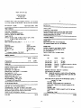
Questionnaire returns indicate that a hatchery may
replace 5 to 10 pairs annually, so that the DFO should consider a pre-season
purchase of approximately 200 pairs. Table 5 shows the number of scissors used
and replacement rates at each of the surveyed hatcheries.
HOW DO I DO IT?
1.
PREPARE THE FISH
Preparing the fish for tagging involves proper fish starving and containing
procedures.
Starving Fish
Prior to tagging, the fish should be starved for at least 24 hours and
preferably 48 hours. Starvation will allow stomach evacuation in the first day
resulting in reduced output of ammonia and excretory by-products associated with
stressful fish handling and tagging. Also, it is noted that the fish will "firm
""up" with starvation. Fish that are not starved before tagging have a noticeably
"softer nose cartilage, resulting in increased tag loss. For extended tagging
operations (e.g. Quesnel Hatchery: 850,000 chinook coded-wire tagged over a"20day period), low-ration feeding and starvation routines must be carefully planned
in order to avoid increased tag loss in the fish that are tagged first and undue
stress in the fish that are tagged last.
Containing Fish
In organizing hatchery space and activities in preparation for marking,
two maj or concerns stand out: 1) minimizing fish handling before tagging begins,
and 2) providing suitable holding and recovery containers during tagging of
multiple groups of fish while supplying cool, clean water at all times. These
concerns are discussed below.
Fish that are not being marked immediately should be kept as comfortable
as possible prior to tagging. Minimizing fish handling before tagging begins
can be done by avoiding disturbing the entire large raceway in order to obtain
one dipnet of fish. This factor is important given the large numbers of fish
tagged each year at a given hatchery. For example, the Quesnel Hatchery has net
pens within the raceways, so that a portion of the fish can be isolated and
starved wi thout disturbing the rest of the population. Similarly, large channels
or earthen ponds holding fish should have net pens within them to isolate groups
of fish appropriately, rather than seining out large numbers of juveniles, and
holding and starving them as one group. For hatcheries using Capilano troughs,
16
Table 5. comparison of numbers of scissors used and replacement rates at the
surveyed hatcheries, as determined from questionnaire returns.
Hatchery
Big Qualicum
Capilano
Chehalis
Pairs of scissors
Used per Season
(
Pairs of Scissors
Replaced per Season
8
8
3 - 6
6
2 - 4
6
6 - 12
20
20
None to date
9
2
ChemainuB
Chilliwack
Clearwater
Conuma
Eagle
Inch
Kitimat
Little Qualicum
Nitinat
Pallant
Punt ledge
Quesnel
Quinsam
Robertson
Shuswap
Snootli
Spius
Tenderfoot
-
20
12
12
10
12
15 - 20
12
8
16
12
5
10
1 pro per person
6
203 - 225
6
5
6
4
3 - 4
2 - 3
2
6
1 - 2
3 - 4
3
None to date
1 - 2
(
None to date
60
-
67
(
17
the trough should be divided in half, so that at anyone time, only half the fish
are crowded, moved around and subjected to swirling dipnets while the remaining
fish can be shaded and isolated.
Wherever possible, fish should be brought into the tagging area the
previous evening and left to acclimatize overnight before the next day's
pre-tagging crowding and handling. (In some hatcheries, such as the Eagle River,
this' step is not possible due to the water system design that would place the
fish at an unacceptable risk.) Similarly, the manner in which fish are brought
into the tagging area (e.g. number of fish in a bucket) can be a source of
stress, its level governed primarily by species, fish size, water temperature
and other site-specific factors (this concern will not be discussed here).
In general, all the above measures to minimize fish handling should be
observed. However, each hatchery has its own site-specific configuration that
requires individual assessment.
The second concern involves holding and recovery containers. These should
be sufficiently large to contain several hours' or a whole day's supply of fish,
in order to avoid overlapping stresses. Fish held in too small a container will
be stressed from being moved into the tagging area without having a "settling
down" period before the additional stress of tagging. At one hatchery, a 2' x
2' holding box was used that had to be refilled with fish every half hour. This
method resulted in excessive handling in a brief time period and may have
affected the long-term survival of fish.
2.
PREPARE THE AREA
Taging Area
A comfortable and well lit tagging area is an important ingredient in
achieving quality fin clipping and tagging. The area should be warm and dry,
with portable electric heaters made available to individual markers. Heaters
are also useful for warming hands when working in cold water conditions. Good
lighting in the tagging area is essential, especially for fin clipping. Since
most hatcheries do not have sufficient lights available, additional portable
lights should be on hand and ready for use during tagging.
Inflow Water Quality
Ideally, the inflow water supplying the tagging table should be tested for
pH and dissolved oxygen. However, this is not usually done since marginal water
quality is reflected in the condition of the fish during rearing. Nevertheless,
pH and especially dissolved oxygen should be monitored before and not after,
mortalities occur.
Equipment Set-up
It is difficult to compile a standard list of the required marking
equipment since each hatchery has its own facilities.
For example, at one
hatchery tagged fish may be deposited directly into a special recovery trough
constructed in the tagging area for that purpose, with the tag rejects diverted
18
(
into a net within the trough. At another site, all tagged fish may be dropped
into buckets, then removed periodically and placed into recovery containers.
Therefore, an equipment list for the first hatchery would include net liners,
and for the second hatchery a set of specialized buckets.
Although the physical set-up of the area for coded-wire tagging will vary
for each hatchery, each operation should include:
1.
Transfer troughs with flowing water so that size-sorted fish can be
sent to different machines. These troughs should have about a 3"
diameter and a U shaped cross-section, and should pass within easy
reach of each qf the fin clippers.
2.
Leg adjustments on the QCDs. The legs provided by the manufacturer
are about 6" too short, creating a back problem for most workers,
especially those standing. The manufacturer can adjust the QCD legs
for less than $60 per machine. Likewise, the height of the tagging
table is paramount to taggers' comfort and should be considered to
be a primary factor governing tagging success.
3.
Generally, the entire coded-wire tagging crew should be standing.
Taggers sitting behind the machines may not be able to reach around
and tag the fish adequately due to 'an awkward arm movement and a
slow tagging speed.
However, if the tagging machines are
appropriately adjusted for height, both taggers and clippers can
remain seated. For example, the tagging machines at some hatcheries
are mounted directly on a table at a level where taggers can sit and
operate comfortably.
(
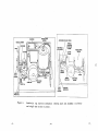
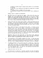
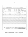
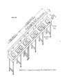
Most hatcheries have their own tagging table set-up in a configuration
that is appropriate for them, and it is not our intention to encourage
unnecessary changes. For the benefit of those who are building new tables for
an existing operation, and for those who are just starting a new operation,
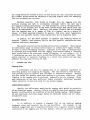
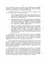
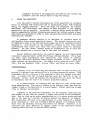
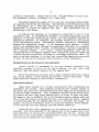
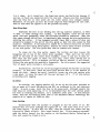
Appendices C and D are provided as a guide. Figures I and 2 show a possible
tagging table set-up for two and three machines respectively.
For fin clipping which usually involves small-sized fish, clippers should
be seated comfortably, their arms resting on the marking table if he or she
prefers.
High quality stools with adjustable seats and backs should be
purchased; otherwise, uncomfortable back problems may develop and fin clipping
quality and speed may deteriorate. As mentioned earlier, the crew must have a
dry, warm area for operating since physical comfort has a major effect on the
marking speed and efficiency.
When clipping fish, many clippers prefer to use magnifiers. These should
be included with the normal fish handling equipment (i.e. basins, net liners,
scissors, anaesthetic, etc.). In the author'S experience, good lighting around
the clippers usually reduces the need for magnifiers. However, magnifiers should
be made available.
When clipping small fish, such as pink and chum fry,
magnifiers may be a necessity as they provide good lighting exactly where needed
and remove the need for harsh room lights overhead. In fact, it may be advisable
to turn off overhead lights if glare on the magnifiers is a problem.
(
•
L2m
TAGGING
TABLE
Standard 3/4 inch
hose fitting
?"
~
Flow
A
_
0.9 m
,
Flow
Transfer
troughs
....
for passing
size-sorted
-0
Anaesthetic
fish
Basin
Tagging
Machine
This clipping basin
sits on top of the
tagging table
,.,..,."
l:....;..:.J
fZ]
•
Figure 1.
Tagging Basin
Clipping Basin
Drain hole
Tagging table set-up for two machines (top view).
2.1
m
Anaesthetic
Basin
Transfer
troughs
for passing
size-sorted
fish
Standard
3/4 inch
hose fitting
_
Flow
Flow
~
....- Flow
N
o
TABLE
TAGGING
Anaesthetic
Basin
Tagging
Machine
o
E21
•
Figure 2.
~
Tagging Basin
Clipping Basin
Drain hole
Tagging table set-up for three machines (top view).
•
~,
~
21
Hand cream and plastic gloves should be made available to markers,
providing their use does not hinder the marking performance. In the author's
experience, most markers who have tried these aids do not like them; however,
this option should be made available.
Counters used in ventral fin clipping, should be cleaned and oiled
regularly, and checked for accuracy and ease of operation. To keep the counters
dry and prevent their rusting, each counter should be enclosed in a small,
plastic sandwich bag and the bag closed ~irm1y. These bags are inexpensive and
can be changed daily or more often as required.
3.
PREPARE THE MACHINES
Unit Assembly
Coded-wire tagging machine units consist of three principal components:
the tag injector, the quality control device (QCD) and the power supply. The
system is shipped essentially ready to operate, providing a few simple assembly
steps are followed.
Note that the following instructions relate to Model MKIII
tagging machines and may differ somewhat from Model MKIV instructions.
1.
Plug the power supply into a 3-wire 120V AC supply line; use of a
grounded supply line is vital.
The system may be operated from
batteries or a generator by using an adapter.
2.
Run a large ground wire (at least 14 gauge) from the post on the
power supply to a ground clamp on the nearest cold water pipe. Wet
conditions while tagging require extra grounding.
3.
Connect the power cable first to the power supply and then to the
injector control box.
4.
Assemble the QCD by installing the supporting legs, attaching the
funnel inlet and flexible water lines, and connecting the water
supply.
5.
Connect the other power cable between the tag injector and the QCD;
then connect the touch switch to the injector.
6.
Remove the blank head mold base which is protecting the needle and
replace it with an appropriate-sized mold for the fish to be tagged;
be careful not to over-tighten the screws.
At this point, the tagging machine is assembled correctly according to
instructions. To ensure proper fish tagging, special attention must be paid to'
appropriate fish size- sorting, head mold size, needle penetration setting,
machine speed, and careful monitoring of tag placement and tag loss.
(
22
Machine Preparation
When a tagging machine is taken out of storage for the spring tagging
program, it must be prepared and adjusted for effective operation. The following
steps are recommended:
1.
Put the rollers back on. New machines allow for a pressure-release
switch that separates the rollers (normally tight-fitting) for
storage. If the rollers are left pressed together, they will develop
a flat spot during the storage period, resulting in erratic tag
placement.
2.
Clean the cutter assembly with isopropyl alcohol and Q-tips prior
to installing the cutter.
3.
Insert the cutter assembly.
present.
4.
Load a spool of blank wire for testing; blank wire is available in
limited quanti ties from Northwest Marine Technology (Telephone:
206-468-3375). Have the wire protrude approximately 3/4" out of the
front of the needle. Turn the machine on, then make 3 or 4 cuts.
Put the interrupt switch "on".
5.
Push the tag button once; this indicates the needle depth into
head mold; Push the button a second time and ensure that the
just falls off the end of the needle.
This ensures accurate
placement.
Any longer or shorter needle depth will result
improper tag placement.
6.
Ensure the machine settings are appropriate for the needle length.
Each machine has a 2-number setting (for "tens" and "units") which
describes how far each tag is inserted down the needle and into the
fish.
The" tens" setting refers to 10 standard half tag lengths
(Le. 0.5 mm x 10), and the "units" setting refers to half a tag
length (i.e. 0.5 mm). At a correct machine setting, the tag should
just falloff the end of the needle when the touch button is pushed
twice. If this does not happen (i.e. needle depth is too shallow
or too deep), adjust the tens/units settings, remembering that each
unit number upward or downward is equal to half a tag length forward
or backward. Normally, the settings should be between 47 and 49.
Larger needles have been installed in some of the newer machines and
also in those sent back for servicing. In this case, a setting of
52 or 53 may have to be used.
7.
Do .a test tag with a nose mold. Replace the blank wire spool with
the correct coded spool.
Cut it two times and turn on the
"interrupt" switch. Push the button once to extend the needle and
leave it in this position. Estimate the correct size of head mold
to be used for the size of fish to be tagged, and place the mold in
position. Turn off the "interrupt" switch. Insert an anaesthetized
test fish and push the button again to tag the fish.
Slice
Check that a good cutter edge is
the
tag
tag
in
(
23
lengthwise the head of the tagged fish and' check for the correct tag
placement (also see section below on Tag Positioning).
4.
CHOOSE THE ANAESTHETIC
It is the author's opinion that proper use of the anaesthetic is a primary
factor in avoiding fish mortaLities and in facilitating proper fish handling
during the tagging operation.
Since new drugs and techniques are rapidly
developing, new biotechnical data should be made available to the tagging
operators as soon as possible. In addition, a special effort should be made to
improve communication between hatcheries and ensure that written records of past
experiences are available in order to train new personnel effectively and avoid
repeating past mistakes.
At permanent marking stations it is desirable to circulate water or
refrigeration lines around anaesthetic basins. This measure reduces the risk
of temperature shock to the fish and allows longer use of the anaesthetic before
changing it.
Good aeration of the anaesthetic solution is also vital since
anaesthetized fish cannot pass water over their gills except by opercular
movement.
For this reason, dosages should be sufficiently low to allow for
opercular movement and a recovery time of less than five minutes.
Several different anaesthetics are used for tagging, the most common being
2-phenoxy (2-phenoxyethanol) and MS-222 (Tricane methanesulfonate). While these
and other types anaesthetize fish effectively, they differ in chemical
composition and elicit different physiological responses in fish.
These and
other concerns are discussed below. The reader is also referred to Bell (1967,
1987); Bell and Blackburn (1984); Britton (1984); and Turvey and Genoe (1984).
2-Phenoxyethanol
2-phenoxy is an oil-based drug and therefore must be mixed correctly by
pouring it vigorously back and forth five or six times between two buckets. This
,requirement can be a nuisance if the anaesthetic baths are changed every half
hour.
A concern that the oil-based drug may cause the injectors to jam, is
unfounded. In fact, since the machines are cleaned every 3 or 4 days, the choice
of anaesthetic does not seem to be a factor' in machine jamming.
It is characteristic of 2-phenoxy that the fish will still twitch after
being anaesthetized. This can be a problem as the fish may" jump" away from the
clipper's hand or the head mold at a crucial moment, thereby resulting in deep
clips or improper tag placement.
2-phenoxy is the preferred anaesthetic for fin clipping, especially for
chum salmon, as the fish can tolerate a longer time period in the anaesthetic
bath. That is, fish can be safely anaesthetized in a 4-5 minute period and then
left in the bath for a further 10 minutes without any apparent ill effects.
This allows about 200 fish to be anaesthetized at a time instead of a smaller
group of perhaps 20. Note that although 2-phenoxy appears to be harmless in the
short term, the sublethal and long-term effects are unknown. Therefore, it is
cautioned that daily immersion of taggers' hands in the anaesthetic-filled
clipping basins may lead to unknown health hazards.
24
(
The dosage of 2-phenoxy depends on the species and fish size, and on the
amount of water and its temperature.
As determined from the questionnaire
returns, the recommended dosage at a pH range of 6.3 to 8.1 is 1 ml of 2-phenoxy
per Imperial gallon of water (i.e. 1:4,546). The dosage should always be tested
before beginning operations to adjust for site- specific factors. Some facilities
anaesthetize in a separate container at full dosage, then distribute
anaesthetized fish to clipper basins at half the dosage strength.
MS-222 (Tricane methanesulfonate)
MS-222 comes in a powdered form and is more easily mixed than the
2-phenoxy. A stock solution is mixed using 100 g MS-222 and 1.0 litres of water.
Subsequently, 10-12 ml of stock solution are used for a 4.5 litre pail of water,
giving a concentration of 222-267 mg/l. The contents are then buffered with
approximately 3 g (or half a teaspoon) of baking soda.
If the water temperature is high (over l4'C), DO NOT BUFFER since high fish
mortalities may result.
However, without the buffering agent, the time to
immobiliiation will be longer.
This can be remedied by increasing _ the
anaesthetic strength (using up to 14 ml/4.5 litre bucket) and lengthening the
fish immersion time in the -anaesthetic bath.
MS-222 anaesthetizes fish somewhat faster than the 2-phenoxy (1 minute for
the above stock solution and pail size). Therefore, smaller batches of fish
(e.g. 80) must be immersed at one time. Filh should not be in the anaesthetic
longer than 2 minutes, and less than that if the water temperature is above lO·C.
While this procedure requires more rapid handling of fish compared to using 2phenoxy, it provides better health conditions for the clippers since clipping
basins should contain only fresh water with anaesthetized fish.
(
Marinal
Marinal is a new fish anaesthetic-that evidently has no residual effects
on adult fish. Therefore, broodstock adults that have been anaesthetized with
Marinal can be immediately killed and used for human consumption. Presumably,
Marinal is also safer for the tagging crew who are constantly absorbing
anaesthetics through skin contact.
The author conducted preliminary tests on Marinal using three different
dosages on both chinook and coho salmon.
All fish were anaesthetized very
quickly but required a long time (6 - 8 minutes) to recover. Reducing the dosage
to very low levels did not shorten the recovery time, and the fish twitched,
similar to the effects of the 2-phenoxy anaesthetic. Since Marinal appears to
be a stronger drug than either 2-phenoxy or MS-222, it is possible that
accidental overdoses will occur more frequently unless the operation is carefully
monitored.
Also, the cost alone will inhibit the use of Marinal; it is
retail-priced at $400 per 100 g, compared to $29 per.lOO g for MS-222.
Carbon Dioxide
Dissolved carbon dioxide is presently used as an anaesthetic at the
Robertson, Tenderfoot and Big Qualicum hatcheries where it appears to be a
(
25
successful alternative. Dosages used are 200 - 300 ppm bubbled in with 0, gas.
The anaesthetic solution is changed 1 to 4 times daily.
The primary beneficial aspect of co, is the lack of residual effects which
are apparent with MS-222 and 2-phenoxy. The Robertson Creek Hatchery has used
CO, successfully for a three-year period but the available information is
insufficient to provide an adequate data base.
More information will be
forthcoming in the future.
As with any new technique, it is necessary to learn how to use it in an
operational sense. At the Tenderfoot Hatchery, a recirculating system was used
initially to maintain dissolved gas levels, but this approach resulted in
temperature increases. To counteract this problem, blocks of ice were placed
in the recirculating system. This measure, however, resulted inconsiderable
uncontrolled temperature change.
At the Robertson Creek Hatchery, a water
chiller was purchased which can keep the anaesthetic bath water at a constant
temperature (ideally 8 -lO·C). However, at this hatchery, warm water temperatures
are a constant problem.
As a result, chilled anaesthetic water may be
considerably below the ambient hatchery water in which the fish were reared and
to which they may be returned, resulting in a secondary temperature shock. In
spite of the above problems, it is clear that a controlled temperature water bath
is vital for the use of dissolved carbon dioxide as a fish anaesthetic.
Recommendations on the Choice of the Anaesthetic
Overall, MS - 222 is recommended as the best workable anaesthetic for
coded-wire tagging, by virtue of its ease of mixing, low cost, short fish
immersion time, and minimal exposure for the tagging team.
Where the marking set-up allows, and at those locations which have a system
that can be adapted, carbon dioxide gas provides a viable alternative. This
method should be explored by each facility individually.
Human Health Hazards
Human health hazards are a further consideration when recommending one
anaesthetic over another. Both 2-phenoxy and MS-222 have residual effects to
the extent that adult fish anaesthetized with these drugs are not permitted to
be sold for human consumption. Also, presumably potential health hazards exist
for workers who have their hands immersed daily in either of these two drugs.
The exposure time is different for on-site hatchery workers tagging their own
fish, since such workers are exposed for only a few weeks each season, compared
to travelling crews who are exposed daily for up to 10 months each season. At
present, no concrete information exists on actual and potential health hazards,
or how these may vary with exposure time and working conditions.
Carbon dioxide, while appearing to be the safest of all the anaesthetics
described, will cause ·headaches in the tagging crew if the tagging area is not
well ventilated, as the gas will eventually bubble into the air. Marinal may
prove to be a very safe workable alternative but it has yet to receive sufficient
field testing to demonstrate its adequacy.
26
5.
CODED-WIRE TAGGING
Basic Operations
1.
Fish are dip-netted from the hatchery holding container into a portable
bucket equipped with an aeration system (one or two airs tones , or a
continuous water flow into the bucket). About 700 - 800 fish can be held
in a 5 gallon pail, assuming a 2.5 g average fish size, with fewer fish
at a larger size. Fish removed from this container are subjected to an
anaesthetic bath where they should remain for no more than a few minutes,
depending on the anaesthetic used. The senior tagger or tag supervisor
nets the anaesthetized fish and distributes them in groups of 20-30 into
each fin clipper's basin.
2.
Each clipper, while the fish are still anaesthetized, gently picks up
individual fish and clips off ·the adipose fin (see section below on Fin
Clipping). The fish is then judged by the clipper to be either "large"
or "small" and placed in the appropriate transfer trough (Figs. 1 and 2).
3.
While the clipped fish is still anaesthetized, each tagger gently picks
up the fish with one hand (head protruding between thumb and forefinger)
and inserts the snout into the nose mold of the tagging machine. With the
other hand, he/she presses the tag eject button to insert the tag into the
nose cartilage and then drops the tagged fish into the QCD funnel of the
tagging machine.
4.
The quality control device of the tagging machine (QCD) then separates the
untagged from the tagged fish.
Fish with a tag is directed by a water
jet into the tagged container. Fish not tagged or accidentally dropped,
automatically goes into the reject container. The number of fish tagged
and the number of rejects are recorded automatically and separately by the
counting device on the QCD machine.
Note that the QCD only identifies that there is a tag somewhere in the
fish.
The only way to determine whether or not the tag placement is
correct is to sacrifice the fish and cut into the nose cartilage.
Improperly tagged fish may have the tag close to the surface of the snout
or deep in the eye socket resulting in subsequent tag loss.
Establishing Fish Size Ranges
As part of the set-up procedure, test fish which were previously sorted
for size by the clippers, are tagged and then killed to verify the correct tag
placement 1. e. in the centre of the nose cartilage. At this point, variousslzed
nose molds are tested to ensure correct tag placement for the likely size range
of fish being handled. The killed fish are then laid on the table for the crew's
reference during fish sorting, so that the appropriate fish size for a given nose
mold is visible to the entire crew. Correct tag placement is also checked at
least every two hours throughout the tagging period (see section below on Tag
Positioning).
(
27
Fish size is an important factor that influences primarily tagging speed
and efficiency. Fish that are smaller than the optimum 2.5 g size are often
harder to hold and handle by the clippers and taggers, thereby slowing down the
operation.
Also, fish that encompass a relatively wide size range or are
unsorted, result in inefficient use of the tagging machines. That is, if one
machine is set up to accommodate 60% of the fish and another to accommodate 40%,
then one tagger remains idle more frequently than the other. Optimally, when
using more than one tagging machine, the size range should overlap so that the
middle range can be handled by either machine, thus maintaining a steady pace
throughout. For this reason, a two-machine system with an overlapping size range
is considered to be very efficient.
It is important to tag a random sample of the hatchery fish regardless of
their size so that a representative size range of the overall hatchery production
is marked. If the fish are graded prior to marking so that all small and large
individuals are excluded and only the medium-sized fish are tagged, a
non-representative group of hatchery fish will be traced through the CWT returns
in the recovery system. This defeats the purpose of tagging. For example, in
some observed cases, fish were sorted prior to tagging so that large and small
fish were set aside, and only the mid- sized fish were retained for marking. This
approach allowed more accurate tag placement and better overall tagging success.
However, the statistics generated from these tag returns did not reflect the
majority of the hatchery population, most of which consisted of either larger
or smaller fish which may have experienced different survival rates from the midsized fish.
Tag Positioning
Tag positioning should be checked by slicing open the fish head
longitudinally with a scalpel. The nose tag should be positioned squarely in
the centre of the nose cartilage (Fig. 3). One fish should be sacrificed hourly
for each tagging machine to avoid missing a gradual change in fish size which
can easily go unnoticed by the crew. Frequent tag positioning checks will also
monitor whether the taggers are getting "ahead" of their machines.
Of all the hatchery sites visited by the author, not one tagging operation
was using the correct head mold size for the size of fish being tagged, or
getting the correct tag placement. Typically, the small fish were tagged too
deep and the large fish not deep enough. Yet the questionnaire returns indicated
that all the hatcheries knew what the correct tag placement was. Two possible
reasons may explain this problem: 1) not knowing what the correct tag placement
looks like when examining the freshly killed fish at the tagging site, and 2)
not sorting the fish for size prior to tagging. It is the author's opinion that
not sorting the fish properly for size was the primary reason for poor tag
placement. This omission is best illustrated by an example. At one hatchery,
a special tagging area was designed and constructed that included a tagging table
with allowance for fish transfer troughs to lead to each of the two or three
tagging machines. Although it would have been a simple task for the clippers
to place large, medium and small sized fish into different troughs in order to
size-grade the fish for each machine, this was not done. Consequently, fish of
all sizes were passed to all the machines. This resulted in small fish being
tagged too deep and larger fish tagged not deep enough, as determined by random
28
(
(A) Proper Tag Placement Within Cartilege
(
(B) Improper Tag Placements
\
(
Figure 3.
Proper (A) and improper (B) coded-wire tag placement.
29
checks for tag placement at each machine. Similarly, at another hatchery, fish
were sorted prior to tagging so that very small fish were graded out.
The
remaining population (90%) ranged from 1.5 g to 4.5 g.
When the tagging
operation commenced, no further size grading was conducted by the clippers so
that the same problem of incorrect tag placement occurred despite two machines
operating. Random tag placement checks showed that although medium-sized fish
were tagged correctly, they represented only 50% of the population. In fact,
a 48-hour examination showed a 6% tag loss in the overall group. In both the
above examples, the fish were healthy and of an appropriate size for tagging,
so that no tag losses need have occurred.
It is imperative for the fin clippers to sort the fish for size during the
tagging operation, to ensure that fish sizes and head molds are closely matched.
Failure to do this will result in poor tag placement and increased tag loss
rate.
We recommend the following measures to correct tag placement:
1.
If the nose tag is not placed squarely in the centre of the nose
cartilage but rather is too high or too low, change the head mold.
A placement that is too high usually indicates too big a mold, while
a placement that is too low usually indicates too small a mold.
2.
If the tag is centered but placed too deep, pUllout the head mold
accordingly.
3.
If the tag is placed too shallow, push the mold in.
Mark the
position on the mold with a pencil to know where you started from.
4.
If unsure which head mold is best for a group of fish, anaesthetize
a random sample of fish and test all the head molds on all the fish
sizes. Try and fit the fish to the mold sizes available.
The manufacturer provides nose molds that come with each machine.
majority of CWTed fish, the following molds are appropriate:
Fish Size
0.7 - 1.0
2.0
3.0
3.0
4.5
10.0
20.0
For the
Head Mold
g
g
g
g
700/1b
200/1b
l20/1b
30/lb
Note that head mold size is stamped in base of mold, and that colour of mold may
change.
The following head mold sizes are available from the Northwest Marine Technology:
30
(
Species
Coho/Chinook
Steelhead
Rainbow
Chum
Pink
Sockeye
Atlantic
Lake Trout
Walleye
Stock Head Mold Sizes
5,lO,15,30,65,120,200,550,llOO/lb
2,3,5,7,ll,20,36,80/1b
5,8,12,18,27,50,90,200/1b
700/1b
2000/1b
60 mm, 90 mm length
7,9,ll,15,25,30,50,lOO,120/lb
5,8,12,18,27,50,90/1b
55,65,125 mm length
The best head molds are often those that are custom-made by the hatchery
staff for a particular group of fish. Each group of fish, especially chinook
and coho salmon, has its own distinctive head and body shape that differs
according to stock, and probably other factors as well.
In the author's
experience, only about 10 - 15% of the fish tagged in British Columbia are passed
through the manufacturer's head molds; the rest are tagged using head molds
custom-fitted by the hatchery staff. Head mold making would make an excellent
workshop subject. Note that the Northwest Marine Technology has an instructional
video and head mold fabrication kit for those who want to make their own molds
(J. Kallshian, per'l. corom. )..
(
Handling Rejects
The presence. or absence of fish .in the "reject" bucket is used as an
indication of the overall tagging success. Therefore, taggers should not remove
rejects from the "reject" bucket during tagging. Instead, the quality control
supervisor should closely monitor the number of rej ects.
Large numbers of
rejects are the first sign of tagging problems, and both the machines and the
tagged fish should be checked immediately and adjustments made.
Fish in the "reject" bucket should be re-anaesthetized and passed again
through the QCD. (Note that unanesthetized fish can actively swim against the
water jets and may be improperly directed). If the QCD shows that the fish are
indeed not tagged, then they are re-tagged and the numbers adjusted to reflect
the total numbers of fish tagged that day. The number of rejects per machine
per day can be determined by recording the tag injector numbers prior to tagging
the rejects and again after the rejects are tagged. Tag reject rates should be
recorded daily for each machine.
If large numbers of fish are found in the "rej ect" bucket (more than 30
or 40 per day per machine), three items should be checked:
1.
OCD problem:
Is the QCD machine able to distinguish accurately
between the presence and absence of a metal tag? Check the "gain"
setting on the machine.
Occasionally the QCD will not sort fish
properly due to a poor adjustment of the water jets. The jets can
(
31
be adjusted to stay on longer to accommodate larger fish, slower
tagging rate and/or weaker water pressure.
2.
Machine problem:
Is the tagging machine not inserting the tag
properly? Improper head mold size, improper needle position, etc.
may be at fault.
3)
Ta"ger problem:
Is the machine operator not tagging correctly?
Taggers do have bad days, and the tagging supervisor should monitor
how the fish is held, how it is inserted into the head mold, and
whether the hand-machine coordination is appropriate (i.e. is the
tagger getting "ahead" of the machine).
[Also, do not forget to check whether tag spool has run out.]
Return all left-over wire and empty spools to the DFO Coded-Wire Tag
Coordinator or to the Program Coordination and Assessment Division. Do not reuse left-over wire for tagging other species or stocks, or for setting up your
tagging machine.
If you need wire for machine set-up, Northwest Marine
Technology (206-468-3375) will provide, free of charge, wire coded with our
agency (02) only.
6.
FIN CLIPPING
Hand Movement
The following sections describe how to hold and manipulate the fish during
fin clipping.
Adipose fin: The fish should be held in the palm of the left hand (for
a right-handed person), with the head of the fish in the centre of the palm,
and the tail of the fish protruding between thumb and forefinger (Fig. 4). Wrap
the hand around the fish and hold it firmly but gently so that only the tail is
protruding. Slide the scissors parallel to and up the back of the fish under
the adipose fin until the scissors stop. Then gently close the scissors to make
an even, smooth cut. The clipping motion should be slow so that the scissors
are closed carefully over the fin.
A motion that is too quick may cause
incorrect angle of the scissors in relation to the fish, and may result in a poor
clip. For example, if the scissors are pointed down, a deep clip will result;
if pointed up, a shallow clip with a peak left over will result. Figure 5 shows
acceptable and unacceptable adipose fin clips.
Sometimes clippers hold the fish upside down so that they almost have to
turn their hand over to get at the adipose fin. This is a very awkward hand
movement and results in-a poor clip. Furthermore, when tagging the last few fish
in a batch, some fish will start reviving from the anaesthetic and will require
32
(
(
(
Figure 4.
Holding and clipping the adipose fin, prior to coded-wire tagging.
33
ACCEPTABLE
Size of actual "bump"
should be no greater
in size than that shown.
No damage to the flesh
occurs.
UNACCEPTABLE
-
-- -- ....... ...
~
)
Size of "bump" is too large
and some flesh has been
removed. Check angle of
scissors.
-- -
- - '"'
...
)
~
,..
,
....-
-
Figure 5.
-- -
A rounding off effect is
a sign of dull scissors
which tend to slide off
the fin as opposed to
clipping through .
Clip is too deep and a
large area of white flesh
is showing.
Acceptable and unacceptable adipose fin clips.
(
34
a very firm hold. If the hand movement is incorrect, the fish may wiggle at a
critical clipping moment, often resulting in a deep clip.
Ventral fin: Ventral fin clipping is the most common marking alternative
to adipose coded-wire tagging. The fish is held upside down in the palm of the
left hand (for a right-handed person) and supported with the thumb and first two
fingers, the thumb holding the head and the belly pointing out.
Other workers
prefer to hold the fish with the fish's head held firmly by the thumb and first
two fingers, with the entire body of the fish, from the gills down, suspended
in the air. Either position can be 'used depending on the clipper. When the
fish is in position, slide the scissors up the belly toward the fins, separate
the two fins and make the cut. Note that in order to take off the left ventral
fin, the fin on the left (upper) side of the fish must be taken off since the
fish is upside down. It is surprising how many clippers forget this.
A good ventral clip involves clipping the fin at the joint where the fin
articulates with the body, so that the fin clipper can feel the "crunch" of
scissors cutting the bone rather than the fleshy fin.
Conduct a "clip check". After the initial cut,
up to the fin and check that the entire ventral fin is
of fin that is next to the centre line of the fish
difficult to remove and clip checking is worthwhile to
is cleanly cut-off.
slide the scissors back
cut off. Often a strip
(the button-up line) is
ensure that this "tail"
Adipose and ventral fins: When clipping both the adipose and ventral fins
some workers may clip the adipose first and then the ventral or vice versa. A
common method for holding the fish when clipping both the adipose and ventral
fins, is to place the fish farther down the hand in the groove between the first
and second fingers, with the thumb holding the head. Then after clipping the
adipose fin, the fish is turned with .the thumb, flipped over on its back, and
the ventral fin clipped. Those clippers who hold the fish between their fingers
usually use their thumb to turn the fish to clip the second fin, while those who
hold the fish with the body suspended in the air usually twist the hand to clip
the second fin.
(
WHAT SHOULD I BE LOOKING FOR?
1.
QUALITY CONTROL CHECKS - GENERAL
Always conduct quality control checks.
It is human nature that better
tagging performance will be obtained with frequent quality control checks.
Check frequently tag positioning, tag retention, fin clip quality, mortality
levels and marking speed. These quality control checks are summarized below.
1)
Tag positioning: Coded-wire tag placement in the nose cartilage of
the fish should be checked most frequently.
One fish should be
sacrificed hourly for each machine, and the sampled fish laid out
for better size-referencing while sorting (see also sec·tion above
on Tag Positioning).
(
35
2)
Tag retention: It is important to check for tag retention every 24
hours and correlate tag loss rates with each machine. Coded-wire
tag retention estimates serve to evaluate the quality of the tagging
operation while it is in progress, rather than just to adjust the
numbers of tagged fish released. Tag retention estimates are an
important part of quality control on each machine and tagger, and
provide a fast indicator of tagging success.
3)
Fin clip quality:
For adipose fin clipping, both the marking
supervisor and the taggers should check clips constantly and make
the clippers aware of any problems immediately.
For ventral fin
clipping, a minimum of 10 fish per clipper four times per day should
be checked visually.
Ideally, this monitoring will require one
full-time person conducting CORstant quality control checks.
4)
Fish mortality:
Daily fish mortalities can vary from several
hundred to one or two per marker.
In most cases, no mortalities
need occur if proper fish handling and anaesthetic techniques are
used. A marking operation that has from 50 to 100 mortalities per
day indicates a problem and the reasons should be closely examined.
It is therefore important to keep an accurate ongoing count of
mortalities.
5)
Marking speed: The overall pace of the tagging operation should
increase only after quality control standards are 'safeguarded. For
a two-machine coded-wire tagging operation and a standard 8-hour
work day, 14,000 - 20,000 fish per day is a reasonable rate.
It is recommended that one hatchery worker be assigned during the marking
operation to supervise the supply of fish to markers, perform quality control
checks, summarize data, and transfer marked fish back to the rearing containers.
This person should also be the one ultimately responsible for the success of the
marking operation and should at least participate in, if not be responsible for,
the hiring and assessment of the contract markers and the overall performance
of the marking contractor. Quality control checks involving tag retention, fin
clip quality, fish mortality and speed of tagging are discussed in separate
sections below.
2.
CODED-WIRE TAGGING
Tag Retention
Tag retention checks indicate whether or not the fish are retaining their
coded-wire tags. Both short-term and long-term tag retention checks should be
conducted. These are very important as the consequences of high tag losses are
substantial. D. Bailey (pers. comm., DFO, Vancouver) estimated that it cost
at least $30 to grow each fish, tag it, recover it in the fishery, dissect the
36
head and enter the statistical information. All of this work and
nullified if no tag is found inside the fish to decode. In addition,
impossible to determine the true fishery contribution of a hatchery
group if a biased segment of the adult population is recovered (e.g.
large fish lost their pins or only one size group was tagged).
(
expense is
it becomes
production
if all the
Short-term tag retention: Tag loss estimates are made by taking a random
sample of 100 tagged fish and passing them down the spout and into the QCD. If.
any of the fish enter the reject bucket they are then passed again through the
system, and once again unless they clearly indicate a tag.
This level of
repetition is necessary since the QCD cannot be totally relied on for a variety
of reasons. For our purposes, the term "tag loss" refers to the percent of the
100 fish that are definitely untagged.
The term "tag retention" is its
reciprocal (i.e. if there is 2% tag loss, then there is 98% tag retention).
It is recommended that short-term tag loss estimates be conducted every
24 hours. If there is a 48-hour delay before finding out that tag losses are
high, a day is lost in which to correct poor tag placement involving perhaps
14,000 to 20,000 fish. Daily tag loss estimates also provide a good immediate
indication of the overall success of the operation.
Short-term tag loss estimates should be conducted on each machine
separately i.e. if four machines are operating, then four separate batches of
fish should be checked. This approach is essential to isolate the reasons for
poor tag placement since the reasons are often machine- or tagger-specific (e.g.
incorrect head mold, poor size-sorting of fish and improper handling by tagger).
Therefore, if machine #4 shows a 4% tag loss while machines #1 and #2 show a
negligible tag loss, then the supervisor can concentrate on the machine #4 and
its tagger to find the problem.
Long-term tag retention: Long-term tag loss estimates should be performed
just prior to release of the fish, and compared to the 24-hour results. It is
the author's experience that in properly tagged fish, any tag loss will occur
in the first 24 hours, so that the long-term tag loss just before release should
be at the same level as the 24-hour loss. For example, at the Quesnel Hatchery,
tag loss was estimated daily on four machines, and also prior to release from
the hatchery (1. e. up to 2 months after tagging).
In this example, the
difference between the long-term and the 24-hour tag loss estimates was virtually
zero. The average fish size at tagging was 1.8 g indicating that large numbers
of 1.0 g fish were also tagged with nearly 100% long-term tag retention. In fish
this small, the area of nose cartilage exposed to the head mold is also small
so that the use of the right head mold and proper size-sorting of fish are vital.
The Enhancement Operations Division has expressed the following concerns
to Stock Enhancement Officers regarding the need for long-term tag retention
sampling (C. Cross, DFO Memo, December 29, 1989):
"Recent work has suggested that our current tag retention sampling is
inadequate. Studies from other agencies have indicated that we should be
sampling a minimum of 500 and, if possible, up to 2,000 marked fish,
depending on the tagged population size, and that the long-term tag
retention checks should be conducted no· sooner than one month after
(
37
tagging. Recommended sample sizes for each species and tagging "block"
(1. e. all tag codes pooled) are as follows:
Total Tagged Population
(tagged fish only with
all tag codes for one
species pooled)
10,000
20,000
30,000
40,000 or greater
Recommended
Number of Tagged Fish to
Retain for Long-Term Tag
Retention Check
500
1,000
1,500
2,000
We would like to begin incorporating more rigorous long-term tag retention
check proce-dures for all species receiving CWT' s. A suggested sampling
regime is to pool a portion of each day's tagging from each tagger in a
small container held separately from the rest of the population in e.g.
a Capi1ano trough, or a small floating net pen in the raceway. Note that
a separate container for each tagger and day is not required. Rather, all
of these" subsamp1es" can be pooled together to provide a larger composite
sample in the one separate container. For a given species, all tag codes
and stocks can be pooled to make up the sample but the representation of
each tag code should be proportional to that tag code's representation in
the total tagged population. If it is desired to maintain stocks of a
species separately, the above table can be used to calculate the sample
size.
Check the fish for tags with a tag detector as they are collected for the
sample and record the number of fish both with and without tags. Do not
remove or re-tag fish which are not tagged.
Conduct the final tag
retention check on the whole sample 4 weeks (minimum 3 weeks) after the
last group of tagged fish was added to the sample. This may mean retaining
the sample for a short time after the rest of the group has been released.
As you conduct the tag retention check, you should also count and record
the number of fish which are carrying a tag but not carrying a recognizable
adipose clip.
Pooling all marks in this way will generate a single long-term tag loss
rate for the entire species, with each tag code having the same tag loss
rate. This is the tag loss rate you should use in the release reports.
For operational purposes, you will probably want to continue your 24-hour
retention checks to ensure that taggers are maintaining tag placement and
general tag quality standards."
At a tag loss rate greater than 2%, it is unlikely that a random sample
of the total fish size range is tagged. In the author's experience, a 0.5% tag
loss rate is a normal performance standard and a zero tag loss (or 100% tag
(
38
retention) should be the ultimate goal of taggers. In reality, many hatcheries
report considerably higher tag loss rates (e.g. 4 - 5%, Table 6) and are
apparently unaware that they could do better. It is important that the reasons
for the higher tag loss rates be examined and understood since most factors (e. g.
correct fish sorting, correctly sized head molds, tag placement checks, frequent
tag loss estimates) are under the control of the tagging crew and can be easily
corrected once the problem is identified.
3.
ADIPOSE FIN CLIPPING
Clip Checking
Both the supervisor and the taggers should check adipose clips constantly
and alert the clippers immediately of any problems.
The tagging supervisor
should check the adipose clips visually by taking fish out of the taggers' basins
prior to coded-wire tagging, or if possible, from the sorting troughs so that
individual clippers can be identified.
Adipose fins are best inspected by
placing an anaesthetized clipped fish in a water-filled vial, holding it up to
a light source and viewing with a naked eye or through a magnifier. The taggers
can check for poor clips during the tagging process. Although deep clips are
usually not apparent to the taggers, peaks or bumps of adipose fins will often
be noticed when glancing at the anaesthetized fish in the basin prior to tagging.
Determination of Good and Poor Adipose Clips
A good adipose clip is one which is cut neither too deep nor too shallow,
and where no evidence exists that the fin was ever present when viewed under a
dissecting microscope or through a magnifier.
(For correct fin clipping
technique, see section above on Fin Clipping - Hand Movement.)
(
The two most commonly encountered problems in adipose fin clipping are
clips that are too deep or too shallow. Too deep a clip will be visible as a
white spot in the clipped area indicating that some skin was taken off (Fig. 5).
Since any scalping of the back of the fry may result in fish mortality, such
clipping should be discontinued. A proper clipping technique will not eliminate
deep cuts completely, but will reduce their incidence to perhaps 10 to 20 fish
per day, instead of 15-20% of the total group or, in one documented case, over
50% of the fish tagged.
Too shallow a clip will appear as a peak or a bump of an adipose fin left
on the clipped fish and will be visible when the fish is turned sideways (Fig.
5).
The most common problem is to leave a tip at the anterior part of the
adipose fin.
Such an incomplete clip, especially on small fish, will likely
result in regeneration.
Adipose Fin Regeneration
The degree of regeneration of an incompletely clipped adipose fin is still
unclear. At the Capilano Hatchery, it appears that coho fry coded-wire tagged
but left with a considerable bump on the fin have matured to adults with the
adipose fin remaining as a large bump, without any apparent regeneration.
However, since no control studies were conducted to identify how many fish with
/
(
39
Table 6.
Hatchery
Comparison of tag loss and fish mortality rates considered acceptable
at the surveyed hatcheries.
Species
Weight (g)
% Tag Loss
24 hr - 96 hr
% Mortality
Capilano
Coho
Chinook
10 - 20
2.5 - 8
5'
5'
<0.25
<0.25
Chehalis
Chum
Chinook
Coho
0.9
1.5
9
3
3
3
0.5
0.5
0.5
Chilliwack
Coho
Chinook
15
6
2
2
Clearwater
Chinook
Coho
>3.0
>3.0
<5
<5
0
0
conuma
Coho
Chinook
10
3
1 - 2
1 - 2
0.5
0.25
Eagle
Chinook
Coho
2.1
1.6
2
3.5
<0.5
<0.5
Inch
Chum
Coho
Chinook
0.9 - 1.1
13 - 20
5 - 10
5
5
5
0.5
0.5
0.5
Kitimat
Chinook
Chum
Coho
10
1 - 2
20
1 - 2
10
5
1 - 2
0
<1.0
0
Chinook
4
o-
1.0
Nitinat
Chinook
Coho
2.2 - 4
1.2 - 5
0 - 3.5
0.4
0.1 - 0.2
.05
Pallant
Chum
Coho
Chinook
1.5 - 2.5
2
2.5
<2 - 5
<2 - 3
<2 - 3
<2.0
<1.0
<1.0
Punt ledge
Coho
Coho
Chinook
Chum
2.25
15
5.5
1
2
2
2
2
0.1
0.1
0.1
0.1
Quesnel
Chinook
Coho
2
5
1
1
0.4
0.4
Quinsam
Chinook,Coho
o-
Robertson
All Species
1 - 2
0.1
Snootli
Chinook
Coho
2 - 5
1.5
6 - 10'
3
0.4'
spius
Chinook, Coho
Chinook
2.5 - 5
3 - 5
4
1
Little
Qualicum
-
, Over a 2-week period.
b Up to one month holding period.
, Over a 7 to 10-day period.
, Up to 10% loss after 5 days.
e
Per week.
, Over an a-month period.
5
--
Sb
Sb
-
-
5
2'
7'
<0.1
<0.1
0
<0.05
<1.0
40
(
complete adipose fins also contained coded-wire tags, it is impossible to say
what proportion of the fins did or did not regenerate. J. Thomas (Mark Recovery
Program, pers. comm.) indicated that chum and pink adults which are tagged at
a very small size «1 g), commonly show substantial adipose tip regeneration.
(See also section below on Ventral Fin Clipping - Fin Regeneration.) Therefore,
while a ve'ry minor peak is acceptable, anything larger may lead to regeneration,
and a large peak is not acceptable. It is very difficult, especially with small
fish, to rec1ip properly a second time since this often results in too deep a
clip. This emphasizes the importance of clipping properly the first time.
Other Concerns
The Enhancement Operations Division has expressed the following-concerns
to Stock Enhancement Officers regarding adipose fin clipping (C. Cross, DFO Memo,
December 29, 1989):
"With' the exception of steelhead, international agreement dictates that
adipose clips are ONLY to be used in conjunction with coded-wire tags.
Adipose clips are not to be used as a primary and independent mark. If
there are fish in a tag group which you feel are too small to tag, don't
tag or clip them at all.
Never apply an adipose fin mark (except in
combination with another fin for chum and pink) without attempting to
insert a coded-wire tag.
Note, however, that "adipose only" fish which result from shedding of coded
wire tags,
(
are an expected and acceptable component of coded wire tag
programs. "
4.
VENTRAL FIN CLIPPING
Responsibilities
In a fin marking operation where six clippers are involved, between 250
and 300 fish will be checked each day for ventral fin clip quality. Ideally,
the quality checks should be performed by both the regular hatchery supervisor
and the contractor's marking supervisor. It is also best that in such a large
operation, quality che'cking be a major part of the marking supervisor's duties.
The clipping supervisor anaesthetizes fish, portions them out to the clippers,
conducts quality control checks at frequent intervals (see below), conducts a
similar number of fish count checks (see below), and updates the data records.
However, from a competitive bidding viewpoint, contract marking crews usually
bUdget for a marking supervisor who clips half the time in addition to performing
quality control checks. Whether or not a full-time quality control worker should
be budgeted for, is a matter for the hatchery management to decide.
Container System
Quality control checks are based on the following container system as
practised at the Nitinat Hatchery. Each fin clipper places his or her clipped
fish into a separate recovery basin with a net liner capable of holding up to
1,500 fish. A random sample of clipped fish is removed every few hours from each
clipper's recovery basin and checked for clipping quality (see section below on
(
41
Frequency of Checks). If the quality of fin clipping is satisfactory for the
particular batch of fish, the supervisor will move these fish to a larger
container. ·If the quality is considered unsatisfactory, the supervisor has the
option of requesting that the fin clipper rec1ip that group of fish.
Frequency of Checks
The marking supervisor should conduct quality control checks as often as
possible, and at least four times/day/clipper (or just before morning coffee,
lunch, afternoon coffee, and the day's end).
The supervisor takes a random
sample of at least 10 fish from each clipper's recovery basin, re-anaesthetizes
them and checks for ventral fin clip quality.
Under this system, each fin
clipper will have at least 40 fish sampled randomly each day from his or her
work, and checked for fin clip quality. This means that, given a standard crew
size of six clippers, a total of at least 240 fish will be re-anaesthetized and
checked daily. A sample greater than 10 fish per clipper is normally unnecessary.
as poor ventral clips are usually repeated sufficiently often that they are
evident in a sample of 10.
Sampling 20 fish per clipper rarely changes the
outcome of the quality control checks. However, more frequent checks are very
desirable, as long as the checks are done at the end of the period when the
entire production for each clipper is subject to sampling. In general, there
are never enough quality control checks.
Count Checks
A count check taken by the supervisor is recommended to ensure that both
the clipper and the counter provide accurate counts. This should be done for
each clipper at least twice daily at random times. Fish count checks will also
serve to discourage competitiveness among clippers to clip more fish than their
team-mates.
Such competitiveness usually leads to substandard clips and
sometimes inflated numbers. While on the job, clippers are able to see only
their own counter and basin.
The supervisor records the numbers from each
counter and then resets it to zero. It is human nature that workers will want
to see the supervisor's clipping records to compare their own performance with
that of the other clippers.
It is recommended that the records remain
confidential, and that clippers ask their supervisor for ways in which they
could improve.
Visibility of the Ventral Fin Clip Area
When checking for ventral fin clip quality, a small number of anaesthetized
fish should be placed in a water-filled glass vial, and viewed under a magnifier
with a good light source. The vial should be turned around in the light to allow
the curve of the glass to magnify the fins sufficiently to look at the
completeness of the clip. Although dissecting microscopes also have been used
for this purpose, they usually result in slower checking (i. e. require more
adjustment time), and cause more eye strain. Also, microscopes generally do not
allow accurate viewing of the fin clip area.
42
(
Determination of Good and Poor Ventral Clips
When the ventral fin is clipped properly, the clipper should 'feel a small
"crunch" indicating that the joint of muscle and bone tissue (where the fin meets
the body of the fish) has been amputated, After completing what feels like a
proper clip, the clipper should visually check that the cut has 'not been too
deep. In a deep cut, the body cavity may be exposed and such fish will succumb
fairly quickly after handling. If the clipper feels that he or she is cutting
air, then the critical wad of tissue has probably been missed.
If the clipper is getting poor clips, the problem can be corrected in the
vast majority of cases by fixing or changing the scissors. It is poor economy
to hire a team of clippers to mark thousands of fish, yet place the work quality
in jeopardy through lack of good scissors.
However, if the scissors prove to be adequate, then the individual clipper
is at 'fault and should be monitored for the following: how the fish is held,
whether the scissors are held at the proper angle, what part of the scissors is
used for clipping (perhaps the tips are used when the back of the scissors might
be better), and whether clipping is done too fast. The clipping supervisor must
be prepared to re-instruct the clipper, accept slower speed, and carefully check
virtually every other fish until a correct clip is obtained, At times, however,
an individual worker simply does not have the patience or manual dexterity to
do the job, and should be replaced.
The determining factor for good or poor ventral clips is the appearance
of the returning adults.
Generally, the Mark Recovery contractor is fully
experienced in identifying clips.
In fact, the present contractor has taken
great pains to ensure whether a clip is pr'esent or not, including feeling for
the bumps on the ventral fin rays where regeneration may have occurred. However,
when large numbers of fish are being checked for marks (usually the case with
pink and chum), it is easy to miss questionable fin clips. Also in hatchery
situations, checking for marks is rarely the only activity, and both questionable
and good marks can often be missed by the busy and perhaps inexperienced staff.
(
In most situations, it is fairly easy to determine a true ventral clip.
Occassionally, the ventral fin may be obviously misshapen in the returning adult.
In the case where the "tail" of the ventral fin remains, the evidence of a clip
is unquestionable despite a partial regrowth of the fin.
In this .case, the
ventral "tail" remaining on the fish should be considered a good clip. When in
doubt, the bumps on the fin rays where the fin regenerated are usually obvious
on close inspection. In questionable situations, bite marks and other scars are
often present on the fish body wall to indicate naturally-missing fins rather
than true clips.
It is recommended that during clipping all ventral fin clips ,be judged
either good or poor, and the clip counts adjusted accordingly. This approach
rejects the 4-zone system that had been used previously to judge ventral fin
clips. The 4-zone system determined percentage reductions in clip counts based
on the zone of the fin where the clip was made and the likelihood of
regeneration. If a portion of the fin was left unclipped, it was possible that
the fin would regenerate in such a way that it was obvious it was clipped,
(
43
Hence, a partial clip could be just as effective a'mark as having the whole fin
missing. However, the degree to which the clip counts should be adjusted was
questionable (i.e, should 25% of the counts be discounted if 1/4 of the fin
remains?). On the other hand, with a good/poor system, if a clip is judged as
poor, it should be clearly discounted.
Thus, during a quality control cheek, if 1 in 10 fish is judged to be a
poor clip, then the number of fish clipped in the 2-hour batch that was sampled
is adjusted down by 10%. This will ensure that at least 90% of the fish are
known to have good clips, with no chance of regeneration.
Therefore, if a
clipping team clips 56,000 fish but quality control checks indicate an overall
10% incidence of poor clips, the records will show that only about 50,400 fish
were definitely released with good clips.
Fin Regeneration
Data on fin regeneration rates are scarce, at least partly due to the time
lag between juvenile marking and adult recovery.
Unlike coded-wire tagging
where tag losses can be monitored after 24 hours, fin clippers must wait a period
of years to obtain any tangible evidence of their clipping effectiveness. At
this time, two examples of fin regeneration can be considered.
The effectiveness of pink salmon fin clipping was examined by Bams (1972,
1979). In this case, 85,000 Headquarter5 Creek fry and 77,000 unfed hatchery
fry (weights approximately 0.24 g) were released with AdRV and AdLV fin clips
respectively. Returning marked adults survived at 1.24% (hatchery) and 1.19%
(creek), as determined by recovering marked adults from commercial canneries at
Vanco,uver and Namu and from the spawning area. Subsequently, the published data
were-,. re-examined for differential regeneration rates of the two fin types.
Results indicated that the mean regeneration rate was,3.53% for the adipose fin
and 1.11% for the ventral fin.
This indicated a significantly higher
regeneration rate for adipose compared to ventral fins over the four brood years
of study. The study also found that, as the marking crew gained experience over
the four brood year period, the total rate of fin regeneration (adipose and
ventral fins combined) dropped from 9.50% to 1.77%.
In recent years, the Nitinat Hatchery also had an opportunity to examine
ventral fin clip regeneration. This survey was made easier by very large returns
of chum salmon to local waters in 1985. In the 1985 fishery, a mark recovery
program was initiated in the Area 21 commercial catch to establish the proportion
of hatchery fish present (MacKenzie MS 1987). Samples taken from high-volume
conveyor belts showed a high incidence of regenerated ventral fins:
Number of
Regenerated
Ventral Fins
Total
123
120
45
288
Degree of
Regeneration
1/4
1/2
3/4
Regenerated Fins
As % of All
Clips Recovered
25%
24%
-.2.!
58%
44
(
In response, the hatchery staff have improved quality control which led
to much lower fin regeneration rates as evidenced in current fishery recoveries
(D. Bailey, pers. comm.).
It is unfortunate that fin clipping conducted
previously did not apply discount factors to poor clips, so that the 4-zone and
percent discount system could be evaluated.
5.
MORTALITY
Acceptable Mortality Leyel
An acceptable tagging mortality level is 100 - 200 mortalities for every
100,000 fish tagged, or 0.1 - 0.2% of the tagged population. At the surveyed
hatcheries, acceptable tagging mortality levels ranged from 0% to <2.0% (Table
6). In fact, it is possible for only 10 or 20 fish in a group of 100,000 to
succumb during a tagging operation. Normal rates should be about 5 mortalities
per day and if this increases to about 40 per day, both the tagging supervisor
and the hatchery manager should begin looking for specific problems. The marking
procedure itself does not result in marking mortalities. However, fish handling
during tagging may be incorrect, or the fish may be smolting, or not fully
recovered from a recent disease treatment, or unhealthy as indicated by increased
mortalities prior to tagging. Specific fish handling concerns that should be
checked when mortalities occur include anaesthetic mis-use, deep clips and poor
water quality.
These and other mortality factors are discussed indiVidually
below.
Anaesthetic Mis-use
(
Anaesthetic mis-use is the primary cause of fish handling mortalities.
The length of time the fish are left in the anaesthetic bath and the
concentration of anaesthetic are the primary concerns. Note that:
1.
Leaving the fish in an anaesthetic bath too long will result in fish
kill.
2.
Not changing the anaesthetic frequently enough will result in oxygen
depletion and incr·ease in the bath temperature, both factors leading
to fish stress and possible mortality. It is the author's experience
that the anaesthetic bath temperature can rise 2°C within just over
half an hour.
This increase is sufficient to shock the fish but
this state is not apparent when they are immobilized.
Assuming correct anaesthetic concentration, the following precautions are
recommended to minimize tagging mortality from anaesthetic mis-use:
1.
Carefully monitor the length of time that the fish are immersed in
the anaesthetic bath.
2.
Change the anaesthetic bath every half hour, and provide constant
aeration· and temperature monitoring to assure adequate oxygen levels
and an even ambient temperature in the anaesthetic bath.
(
45
Since a proper anaesthetizing procedure is a crucial part of the marking
operation, retain the same person in charge of the anaesthetic throughout the
operation if that person shows ability to keep the fish alive. See also section
below on Poor Water Quality.
Deep Clips
Deep clips sustained during adipose fin clipping will expose muscle tissue
which can become fungussed and possibly result in long-term mortality especially
in smolting fish.
Normally, it will take a few days for the injured area to
become covered with fungus and form a visible white spot.
Therefore, it is
important that the marking supervisor check for deep clips both on the clipping
table and in the recovery pens several days later.
Deep clips sustained during ventral fin clipping may expose the body cavity
and kill the fish, usually within 24 hours. This form of mortality is more
immediate compared to the longer-term and far less frequent mortality associated
with deep adipose clips.
Although good quality clipping of ventral fins should take priority over
any remedial post-marking treatment, the following treatments may reduce
mortality. A Malachi te Green dip following marking can be used to control fungal
growth, especially in the event of large numbers of deep clips or mUltiple clips
where the fish are more mutilated (e.g. ventral clips in addition to adipose
clips and coded-wire tagging). Dosages are approximately 1:20,000 (or 1 g per
5 Imperial gallons of water) for a lO-second dip. Such a dip is not recommended
as a preferred practise, as it is now known that Malachite Green is a carcinogen
affecting human health. This practice is now illegal in the United States.
Fungal growth on clipped fish may be controlled also with antibiotics (in
particular terramycin) wherever water temperatures are high, providing the fish
are already under treatment for disease, or they show other signs of stress.
However, it is recommended that post-marking treatment not include antibiotics,
as such treatment could encourage the growth of resistant fungus strains.
Poor Water Quality
Water quality can deteriorate rapidly during the course of a tagging
operation, causing fish stress and increased mortalities. Water quality testing
should be conducted on 1) source water used at tagging tables, 2) anaesthetic
bath, and 3) receiving water.
1)
Source water used at tagging tables .(e.g. water pumped from the head
tank)
Check the following:
i)
Clarity - should have no suspended solids.
ii)
Dissolved oxygen - should be at or near saturation level.
Increase low oxygen levels with aeration.
46
2.
(
iii)
~
iv)
Temperature - see Table 1 for maximum temperatures during
tagging. Note that having different temperatures in different
holding containers can also stress the transferred fish.
- if it is below the hatchery norm, buffer the anaesthetic
bath.
Anaesthetic bath (see also section above on Anaesthetic Mis-use)
The anaesthetic bath should be changed at least every half hour,
primarily to maintain ambient temperature, but also to ensure a
constant dosage level. Rising temperatures will affect the potency
of the anaesthetic and increase the speed at which the fish succumbs.
Water temperature in the anaesthetic bath can change very rapidly,
especially when operating outdoors in warm weather. A temperature
change of 1-2'C is normally within operational limits but beyond this
level the anaesthetic solution must be changed. Recirculating water
is primarily intended to maintain a constant temperature but such
water often heats up nearly as much as standing water, as indicated
by thermometer checks. A thermometer should be kept at the bottom
of the anaesthetic bath and in each of the clipping basins.
In addition to temperature checks, conduct pH and dissolved oxygen
checks hourly in the anaesthetic bath.
Buffer with sodium
bicarbonate when necessary, and ensure that all anaesthetic bath
(.
~
water is aerated.
3.
Receiving water
Receiving water for tagged fish also should be checked for
oxygen, pH, and temperature: In particular, water in small
containers should be aerated.
If water testing is not
evidence of stressed fish should initiate water testing and
dissolved
receiving
done, any
immediate
corrective action.
Other Factors
Assuming that the anaesthetic procedure, deep clips and water quality are
not a problem, a comparison of daily pre- and post-tagging mortalities should
indicate whether or not a disease factor is affecting fish health. This step
is necessary since severity of the disease may be aggravated by the added stress·
of tagging and possibly high water temperatures (e.g. 14 - lS'C). If tagging
cannot be postponed until water temperatures decline and/or disease factors
abate, the only option left is antibiotic treatment. It is recommended that 10
days of terramycin treatment be undertaken after tagging in order to keep other
infectious agents reduced until the fish recover (G. Hoskins, Pacific Biological
Station, pers. comm.).
Incorrect tag placement itself usually does not cause immediate mortality,
although the long-term effect of improperly placed tags is unknown. However,
if the tag is placed too deep in the fish, that tag will normally come out
through the eye socket, resulting in both tag loss and possible fish blindness.
(
47
6.
SPEED AND EFFICIENCY STANDARDS
The overall pace of a marking operation should increase only after quality
control standards are safeguarded. The first one or two days of marking should
focus on training workers to tag and clip properly, while closely monitoring tag
placement, tag loss and mortalities, and accepting a lower than normal tagging
rate. Once quality marking is assured, the speed of the operation will improve
so that the overall average numbers marked per day will likely be acceptable.
Minimum accepted speed standards for ventral fin clipping are not provided
here specifically, since this is an individual variable -- once quality clipping
is demonstrated, speed will increase. However, the supervisor should determine
whether or not a worker has sufficient manual dexterity.
According to
questionnaire returns (Appendix E), the average speed per clipper for single
clips is approximately 600 per hour, and for double clips (i.e. adipose-ventral)
is 400 per hour.
Unlike the fin clipping programs, coded-wire tagging is a team effort and
some speed and efficiency standards are appropriate:
No. of
Machines
No. of
Taggers
No. of
Clippers
Number of Fish
CWTed per Day
1
1
2
6,000
10,000
2
2
4
14,000
20,000
3
3
6
26,000
28,000
The primary factors affecting the tagging speed are the experience of the
crew (especially the taggers), the level of teamwork they exhibit, and the speed
of the tagging machines themselves. Minimum marking standards should be about
1,000 fish tagged per machine per hour, or about 7,000 fish daily for a
one-machine operation and 14,000 fish daily for two machines. Note that this
standard will be reasonable for some operations but not for others.
In
particular, a hatchery that undertakes tagging for only one or two months every
year will have difficulty assembling an experienced crew and maintaining optimum
tagging conditions. By comparison, a contract tagging crew that is operating
perhaps eight or nine months every year should be expected to show a greater
degree of efficiency. It is possible for an experienced crew to reach an average
of 8,500 - 9,000 fish per day per machine,and thus tag 18,000 fish per day using
two machines while still maintaining 100% tag retention.
Smaller fish (2 g to 10 g) can be tagged at a minimum speed of 14,000 per
day for two machines (as above) but in reality the operation should be reaching
16,000 to 18,000 per day for a moderately efficient crew. Very large fish (15 g
and up) are tagged more slowly, so that minimum speed standards are about 12,000
fish per day for two machines.
48
(
It is assumed that at the above speed standards, tagging mortalities and
tag losses are closely monitored and kept to a minimum. That is, speed must be
a secondary consideration to the quality of tagging. Whenever tag losses reach
more than ·1%, the crew should slow down and correct this problem before
continuing. The tagging objectives are better served by a team that tags 17,000
fish per day with no tag loss than one that tags 20,000 fish per day with 3% or
4% tag loss.
7.
DATA RECORDING
It is important to keep accurate and complete records of each tagging
operation as the tagging proceeds. Such records facilitate quality control and
enable comparison among hatcheries. Based on the author's experience in many
different hatcheries, records should include tag loss rates, mortality rates,
and tagging speed and efficiency standards. These records will allow workers
to have a yardstick against which to measure their own performance. It is also
important to record the numbers of smBfll, diseased or otherwise damaged fish that
are removed from the tagged popUlation, and to adjust the release population
accordingly.
The Enhancement Operations Division has expressed the following concerns
to Stock Enhancement Officers regarding CWT data recording (C. Cross, DFO Memo,
December 29, 1989):
"Please make a brief comment on the release report for any group of fish
which you feel are sufficiently unhealthy at· release as to have lower
survival than normal. Flagging unusual conditions such as this can assist
data users from other agencies.
(
Keep tagging data (e.g. number tagged, number unmarked, etc.) separate for
each tag code. Do not sum these data over two or more tag codes as it can
potentially ruin the data·for any adult analyses. The only exception to
this is a common tag loss rate for several tag codes for a given species,
where all tag codes and stocks are pooled to make up a representational
tag retention sample."
It is recommended that standardized data forms be used, so that they can
be easily interpreted by the Headquarters staff, resulting in better
communication and follow-up throughout. Appendix F contains proposed data record
sheets for coded-wire tagging operations, based on the Quesnel Hatchery format.
Appendix F also includes a proposed data record sheet for fin clipping
operations, based on the Chilliwack Hatchery format, and provides sample data.
A standardized fin clipping form is necessary to provide a proper interpretation
of the clipping results.
The form must show evidence of quality control
checking, frequency of poor clips, and clearly show the number of good clips that
have been released.
(
49
TAGGING MACHINE TROUBLESHOOTING
1.
CLEANING AND MAINTENANCE
Frequency of Cleaning
While the manufacturer generally recommends daily cleaning, this is usually
not necessary. Machine cleaning takes too long at the end of the working day,
and often the machine will jam after it has been cleaned so that the tagging
operation itself is placed at risk. Normally, when the equipment is set up,
everything is cleaned and sterilized, and a thorough machine cleaning will often
be done at the end of each tagging week. In the interim, the machines should
be left "on" 24 hours each day in order to keep the parts warm and dry and
thereby render the cutters less likely to seize up.
The ideal frequency of cleaning tagging machines should be about every
three days, providing that the machines can be left with the power on for 24
hours each day. If the tagging site is remote and requires a generator so that
the power will be turned on and off, then the machines should be cleaned daily.
Cleaning Procedure
Equipment maintenance is based on cleanliness. Always ensure that the
needles and needle carriers are clean and free of grime. Also ensure that the
cutter motor, cutter housing and the cutter itself are clean. When cleaning a
tagging machine, the primary area is the tag injector. The QCD is basically
uncleanable, except for removing surface dirt and grime, and ensuring that the
electrical connections are dry and rust-free. The following steps are provided
for cleaning the tag injector:
1.
Remove the face plate and then remove the needle carrier by undoing 1 or
2 screws (Figure 6). Some machines have the original push arm assembly
(2 screws) while the newer models have a single arm action (1 screw).
Remove the bar assembly and take out the cutter (note which edge is in
place for re-installation later). Soak all the pieces in isopropanol.
2.
While the parts are soaking, dip a Q-tip in isopropanol and clean out the
cutter assembly (i.e. motor that the cutter fits into).
Also, clean
underneath the assembly where water drips in.
3.
The front of the motor drive assembly where the needle goes in and out of
the cutter can be cleaned with fine steel wool and buffed so that the
needle has an easy entry into the cutter assembly. Steel wool is also used
to buff the back of the needle carrier to make sure that it is clean and
smooth so that the needle has an easy entry and exit in that area. Note
that the manufacturer does not recommend the use of steel wool for cleaning
the above parts.
4.
The cutter, face plate, needle and needle carrier, after soaking for a few
minutes, should be dried on a paper towel.
It is important that these
pieces be dried thoroughly before they are reinstalled in the machine.
COUNTER
ACTUATOR WITH SeT SCREW
I
NEEDLE CARRIER
NEEDLE
PUSH ROD
.SHOULDER
LAMP
SCREW
NEEDLE DRIVE
MOTOR
I
':r------" ~ ~
o
'"
,
L:-9
HEAD
MOLD
HOLDER
NEEDLE
PUSH ROD
WIRE DRIVE
t
T
,J. ;'~---1
WIRE DRIVE
MOTOR
MOTOR
HEAD
MOLD
INJECTOR
FACEPLATE
HOLDER
INJECTOR
FACEPLATe
Figure 6,
~
Coded-wire tag injector mechanism
and single arm action (1 piece).
--.
showing push arm assembly
(2 pieces)
~
51
If they are inserted in a wet condition, they will seize, simply because
of the very tight fit of the moving parts.
5.
The cutter should be installed by paying careful attention to aligning it
with the sarne cutting edge as before cleaning. This is done by noting
which edge it was on when first removed. Each cutter pin has a notch on
the top or the bottom, and on one side so that one can determine proper
alignment by the position of the notch and by the plus or minus switch on
the control box. Put the screws back in the cutter.
6.
Slide the needle carrier back into the cutter motor assembly. Place the
drive arm back into the socket on the needle carrier, and put the screw
back on. Carefully position the face plate back on (if not done carefully,
the plate can bend the needle). Continue with additional assembly details
as outlined in the NMT Instruction Manual (Appendix A).
7.
Machine is then loaded with blank wire, put in the "on" mode and run
several times to make sure it is not jamming. If it is jamming, take it
apart and put it back together again as this action usually solves the
problem.
Keep a record of edges on the cutter and of the number of cuts per edge
in order to get the most use out of this piece.
If the cutter is not
re-assemb1ed using the same edge, that edge can be wasted by abandoning one side
after only 10,000 cuts when it could have provided 100,000 cuts .
. Appendices A, Band G contain information from the manufacturer on cleaning
and maintenance of the tagging machines, and describe fully the machine parts
and their assembly. Refer to these appendices for further details.
2.
TAG INJECTOR
Tag Injector Jamming
Jamming is not a major issue, provided the workers are competent at fixing
the problem. Remember that the machine will j am rarely wi th regular maintenance,
i.e. keeping it clean, making sure the back of the needle funnel provides a
smooth, clean entry for the needle, examining the cutting edge and examining the
tags being cut (i.e. looking at the cut tag edge under the microscope to assure
that it is a clean cut). Sometimes a machine will jam all day long and then
perform well for the next two weeks.
Why does a machine jam?
If a machine is not clean.
If the needle is bent.
If the funnel where the wire feeds into the needle has the slightest
scar or dent on it (Fig. 7).
If the cutter edge is worn out and bending the rear of the cut tag.
If the rollers have a worn out spot so that they are not pushing the
wire out properly.
52
(
A
/-"
GOOD
FUNNEL
Q-
DAMAGED
FUNNEL
(
Figure 7.
Needle funnel showing new (A) and worn (B) condition.
(
53
I~ there is a power surge or ,outage and the machine is in the middle
of cycling.
If the wire is not coming out the needle far enough and is sucked
back in.
If a piece of wire is jammed in the wire guide.
If everything is going too well and you haven't had a problem all
day.
Fixing a jam is a process of elimination:
1.
The first step is to load the wire again.
Often this will solve the
problem, but if the machine jams a second time or if you can't reload,
examine the cutter edge and check the cut wire for a clean cut.
Also
review your information on how many cuts have been incurred on that edge.
That is, if 112,000 cuts on that edge were recorded, chances are the cutter
is at fault, and you should move to edge two, three or four.
2.
Clean out the jam, the cutter and the needle. Reload some blank wire and
try again. If you are not getting a good cut and a minimum of 25,000 cuts
are recorded on that side, then try a new edge. If you try a cutter edge
that you know is absolutely new and the machine still jams, then it is time
to look for another reason.
3.
Next, check the funnel at the back cf the needle.
If there is the
slightest scar or dent in that surface, the wire will not feed properly
and will cause a jam.
Take the needle out and examine the funnel surface
to see that it is clean and smooth. Note that the needle must extend out
the back of the needle carrier at least 1/16th of an inch. If the needle
is flush with the back of the needle carrier, the likely reason for jamming
is that the wire cannot feed in, i.e. there is too great a gap between the
back 'of the needle and the front of the cutter.
Therefore, first try a new cutter edge. If that doesn't work, check the
funnel at the back of the needle for scars, and at the same time ensure
that the needle is protruding the correct 1/16th of an inch.
4.
If the machine is still jamming, examine the rollers. Do they have deep
ruts that could be causing the roller to slip and not push the tag out
properly, and instead are possibly sucking the tag back in? Check also
the drive roller alignment/adjustment, and replace rollers if necessary.
5.
If jamming continues, look at how far the wire is coming out. Every time
a new needle is put in, check the setting on the tag depth (units and
tens) since every needle is a slightly different length. Also, ensure
that the tag is just falling off the end of the new needle when the machine
is in the interrupt mode.
If after all the checking the machine still
jams, the problem is more serious.
6.
Change the cutter one last time.
This final point is important. Consider a machine jam where the machine
would tag five fish and then jam although everything was cleaned and replaced
54
(
3 or 4 times. As it turned out, the brand new cutter was faulty but because it
was new, no fault was suspected until the very end. Chances are that everything
else was fine but at that point all the other pieces Were changed anyway.
Therefore, do not give up until the cutter edge has been 'changed one last time,
even if this does not appear to be the problem initially.
Poor Wire Feed
Sometimes the wire is not feeding into the tag injector properly, or when
it does, it comes through very stiffly. If this happens, clean out the wire
guide (see next paragraph) since the following problem is suspected. When the
wire comes through the rollers, it immediately goes through the wire guide before
entering the cutter. It has happened several times that a piece of wire can
actually be jammed in the end of the wire guide so that the wire cannot be fed
properly. Therefore, if the machine is jammed for no obvious reason but you know
that the wire isn't being fed properly, chances are that a piece of wire is stuck
in the wire guide. The wire guide must then be removed and cleaned.
To clean out the wire guide, remove the rollers and also loosen the
hexagonal nut on top of the cutter motor assembly.
Then, pullout the wire
guide at the back of the cutter motor assembly, clean it and put it back in.
Note that the wire guide is about one inch long, cos ts about $50.00 and is
extremely brittle. If it is dropped, pulled too hard or twisted, it will break.
Without the wire guide the machine is inoperable. For this reason, the suggested
list of spare parts includes a wire guide.
(
Occasionally, the fish are not being tagged although the machine is cycling
properly. In this case, check the spool wire and see that it is not snarled or
wound too tight. Remove the spool, carefully loosen the wire and replace with
a new spool, or leave the spool off the post and peel off 6 - 8" of wire before
proceeding with tagging.
No Power
On occasion, the tagging machine will be set up and the power switched on
but no power will reach the machine and QCD, as evidenced by the red indicator
light. In such a case, check the fuse in the power pack, although usually the
fuse does not need replacing. If it is determined that the cord carries power
but none is reaching the machine, try a different power pack. If this measure
works, send the non-working power pack to the Northwest Marine Technology for
repairs as it cannot be fixed on site.
Poor Cycling
Occasionally when the machine is plugged in and the power is on, the
machine will not cycle although the lights are on. The first step is to try a
new touch switch. If this does not work, then the control box within the tag
injector is likely at fault. Use a spare control box. If this measure succeeds,
send the faulty control box for repairs to the Northwest Marine Technology as
this unit cannot be fixed on site.
(
55
Sometimes the machine will run erratically, particularly in a situation
where the power source is a generator that may not be providing close to 120 V.
The machines do not require all of 120 V (they will run on 115 V) but if the
generator is providing, e.g. 103 V, the tagging machines will not run properly.
The cycle will be fast on one fish and slow on the next, with no consistency as
to how fast the tag injector is cycling. Also, the QCD will often start clicking
for no apparent reason; it will detect one fish but not the next. Again in this
case, the generator may not be providing sufficient power.
It may be that
although the generator is a 3,500 watt unit, it needs a tune up or perhaps needs
to be run faster in order to reach the 120 V required.
Since the tagging
machines will continue to operate (although erratically) on low voltage, it is
sometimes difficult to determine the cause of erratic performance unless there
is a voltage regulator on the generator that shows that the output is below the
required 115 - 120 V.
Head Mutilation
After a fish is tagged, a half-moon shape should be visible with the naked
eye at the point where the needle went in, rather than a round, white hole. The
latter type of hole indicates that the needle has become blunted with use and
perhaps has developed a straight edge instead of an angle. Sharpen the needle
and increase the angle to provide a good clean entry into the fish head. Besides
causing a fungus problem, a blunted needle will leave an easy exit path for the
tag that was just injected.
Improper Tag Length
Grooved rollers can result in the tag being cut off at the wrong length
since the tag was not pushed out all the way. The correct remedy is to replace
the rollers entirely when they get a groove or a rut in them, then recheck for
correct tag cut off length. It is a mistake to remove the rollers, shave them
down to eliminate the groove and then reinstall them, since the diameter of the
rollers determines the tag length. That is, a smaller roller will result in a
shorter tag length cut.
Occasionally, the tag injector will load properly, the wire will be
extended but not cut off. In this case, the cutter is seized and the remedy is
to remove it, clean it by soaking in isopropanol, and reinsert it.
3.
QUALITY CONTROL DEVICE (QCD)
The control box within the QCD has three screws: a gain, delay and pitch.
The gain is used to detect the tag, the delay to determine the amount of time
that the water jet stays on, and the pitch is merely the horn device on the QCD.
The QCD should be operated with the lid open, and with the jet mechanism
clearly visible so that the operator can adjust water flow, delay and even the
gain without disturbing the operation.
This approach is more efficient for
conducting QCD repairs than having to remove the tag injector, opening the lid,
removing the solenoid, cleaning, replacing the solenoid, putting the lid back
on, etc. Note, however, that the manufacturer recommends that the QCD lid remain
56
(
closed, since an open lid allows more water on the QeD control box, and this is
a major cause of failure.
When troubleshooting the QeD, first ensure that the gain, delay and pitch
settings are appropriate, as described in the following sections.
Gain Setting
The setting on the "gain" screw allows detection of the tag. Under normal
conditions, if the screw is turned all the way to the right, set, then turned
back 1/4", this process usually achieves an ideal setting for the machine to
detect the tag. However, if the crew is working under fluorescent lights, the
lights tend to throw off the QeD somewhat, so that it may be necessary to turn
the gain switch down another 1/4" because the QeD may click and detect a fish
when none is present.
Occasionally the QeD will not detect a tag, although a clearly tagged fish
passes through. In this case, the gain should be checked to ensure that it is
turned On fully, then turned back 1/4". It is possible that somehow the "gain"
screw has been turned back and is not capable of detecting the tag. However,
if this measure is unsuccessful, the only other possibility is that the QeD
control box has malfunctioned. To test this, switch control boxes with another
machine and if the problem is resolved, send the faulty control box for repairs.
In summary then, if a fish is dropped through the QeD, and no clicking noise
results, check the "gain" screw and failing that, switch control boxes from a
QeD that works.
(
In the event that the QeD begins clicking for no apparent reason and a
generator is used as a power source, check if the QeD is receiving sufficient
power.
Delay Settin!:
The setting on the "delay" screw determines the amount of time that the
water jet stays on in order to sort the tagged from untagged fish. If larger
fish are being tagged, the delay must be set at a longer jet which can push a
larger fish through. If smaller fish are being tagged, the delay can be set at
a shorter jet with a very fast action so that the tagger is not slowed down
unnecessarily. It is recommended to set the delay switch at the highest speed
possible that will still enable the tagged fish to be pushed over to the correct
side. In practice, turning the "delay" screw to the left decreases the duration
in which a jet ejects a marked fish, so that smaller tagged fish can be pushed
over quickly with little water. Turning the screw to the right increases the
duration up to two or three seconds in which the jet ejects a marked fish.
Finally, the direction of the water jets on the QeD can be adjusted by
hand. The jet can be moved left, right, raised or lowered, to ensure that the
fish goes into the tagged passage with a 99,9% sorting success. Watch the fish
pass down the system and adjust the jets so that the water first hits the fish
on the head, then moves down the fish body.
(
57
No Water Jets
Sometimes when a tagged fish is dropped through the QCD, the click of the
solenoid is heard but the fish still passes into the reject bucket. In this
case, the solenoid is probably plugged up and no water jet comes on to force
the fish into the other stream (the QCD is designed so that the water always runs
into the reject bucket). In this case, it is necessary to take the solenoid out
and unplug it. This action is time consuming. The. solenoid is very sensitive
and it takes only a very small grain of sand to make it inoperable.
This
situation can be avoided by taking two precautions:
1.
Purchase a water filter from the manufacturer ($125). Use of a water
filter has been very effective in reducing the downtime of solenoids.
2.'
Increase the water pressure running through the QCD. This measure
will help flush through any residual sand or grit particles that may
be in the system.
Caution: there is some evidence that water
pressure greater than 40 psi to the QCD (i.e. 25 psi to the solenoid)
may be detrimental to the solenoid, since the spring-loaded core
within the solenoid can be jammed shut. If this happens, lower the
water pressure.
Pitch Setting
The pitch is the horn device on the QCD. If there is more than one QCD
in a room, each machine can be distinguished by its own pitch tone when it is
rejecting fish. It is permissible to cut the wires leading to the speaker as
there is no need to hear the beeping noise all the time. The taggers know when
the machine is rejecting fish because they don't hear the clicking noise of the
solenoid turning the water jet on.
4.
CUTTERS
Selecting an Edge
Each cutter edge must be carefully selected and used in order to maximize
the number of cuts obtained and monitor cutter performance. To set the cutter
on a given edge, note that the inner core of the cutter has a slash mark on it,
indicating which edge is being used. . If the slash mark is up, the machine is
using either edge #1 or #2; if the slash mark is down, the machine is using
either edge #3 or #4. To use cutter edge #1, insert the cutter so that the slash
mark is up, then set the control switch on the control box to "+" so that the
machine will select edge #1.
Recording Number of Cuts
A cutter maintenance book should be kept at each injector box to ensure
that the operators keep a record of cutter use. Most importantly, when other
workers borrow tagging machines, they should also be required to keep a
maintenance. log on the tag injector. This way, when the machine is returned,
the original operators can sort out the history of the cutters and determine
58
(
whether or not the previous operation is a factor in machine jamming.
The
maintenance book should contain a log of any changes to the cutters, the number
of injector counts when the cutters were changed, the date when new needles or
rollers were installed, etc. Figure 8 shows an example of a cutter maintenance
log sheet.
Note that in the event of poor cutter performance, a cutter log
provides valuable reference when dealing with the manufacturer. Table 7 shows
that cutter performance was monitored at only eight of the surveyed hatcheries,
and that estimated cuts per cutter varied widely from 50,000 to 500,000.
In practise, the taggers should begin with edge #1 by setting the tag
injector mechanism as described above, and then recording the start number. If
the machine jams, the first option is to reload the wire and try again. If the
machine still jams and the cutter has done more than 100,000 cuts, then move to
cutter edge #2.
This is done by simply changing the control switch on the
control box from "+" to "-" and by recording the counter number in the
maintenance book. If it is subsequently necessary to change the rollers while
using edge #2, then the counter number when this occurs should·also be recorded.
If the machine begins to jam again and this coincides with, for example 116,000
cuts, then·switch to cutter edge #3. This can be done in two ways: 1) take the
cutter out and turn the inner core over so that the slash mark is now on the
bottom, indicating that edges #3 and #4 can be used, or 2) leave the cutter in
place and move the inner core by turning the knob on the cutter motor (arrow
indicator). When the cutter is rotated, also change the control switch back from
"-" to "+". Most of the time it will be convenient to remove the cutter and
replace it manually. This is because cutter edge changes will be associated with
jams and wire reloads
that require this operation anyway.
However I
it
(
is
possible to change the orientation of the cutter core by simply adjusting the
knob on the cutter motor.
Cutter Maintenance
Cutter maintenance essentially involves cleaning. Every two or three days,
the cutter should be taken out and cleaned properly by removing ~t from the unit,
soaking in isopropyl alcohol, drying thoroughly, and replacing it into the unit.
The slash mark on the cutter core should be in exactly the same position as when
the cutter came out.
When the machine is not in active use, the cutter should be taken out and
cleaned before· storage. Note that the cutter pin and sleeve are a matched set
and should not be intermixed during cleaning and storage. The cutter originally
arrives from the manufacturer in a cardboard box packed with styrofoam, and
should be returned to that box for storage. Make a note on the box which tagging
machine the cutter came from, and refer to the maintenance log to indicate which
cutter edge was used last and what the tag count was when the cutter was removed.
(
59
Hatchery
:
Ie n 01 u too t. Ck.
Date
~~~(.,4:'
Apr. 12.181
.309 94 b
~~~ I bIg ~
,34b" 9 9
f-\o"L/
\
Comments
Tag Injector #
Ma.r. ,(, /8 j
3I
~t...
new cu.tle r . Ins+a.lld - c::J~ (.. #..1he.w 1"011_ r~ ,I\s-w-11t'J - needle ('~o. m e.,(
ch",,,~t c(
C.\.I:\-5
ot-4i .... ui of{' e.vl~ ..
needle i!\ 'E'-\ '" 1/ t' cl
I~~
.2~5 7D~
hl!.W
Is,
"149'\ q;,
C-lA.t\a I"
I'll &'~
1(,,:2351
ed~£
c.tA.tIe .-
<:.\.\.-1-5
Q"t.
Ol
Machine Name/Number :
to
#.;< - 57,os'~..t
t-h ... n~.cI 10 ecl~e ;+ 3
- HI?>, a '1'1
art eo!~~ '1+ oR
d." n eJ Lw Irde ri ~"C£ . c... t"I......
QHo!.'~.,(
K ",J, \"e.-
4D be
re- \r-~ +a. ,I( J-
01"\
~<! 91
6
Note: This record sheet has been filled out to give an example of how the records
could be kept. This. or perhaps a different format, can be adopted. The
important point is to have some record sheet which stays attached inside
each injector box, to record all information pertaining to that machine.
Figure 8.
Proposed record sheet for cutter use and maintenance.
Table 7.
Comparison of numbers of machines, cutters, cutter use and ·machine downtime at the surveyed
hatcheries, as determined from questionnaire returns.
Hatchery
Big Qualicum
capilano
Chehalis
Chemainus
Chilliwack
Clearwater
Conuma
Eagle
Inch
Kitimat
Little Qualicum
Nitinat
Pa11ant
Punt ledge
Quesnel
Quinsam
Robertson
Shuswap
Snoot1i
Spius
Tenderfoot
•
Used
No. of .Spare
Number of Machines
Spares
Borrowed
Cutters
CUtter
Monitoring3
Estimated
cuts/cutter
% Downtime
200-400,000
150,000
150,000
2%
15-30 min/day
10 - 15%
2 - 5%
3 - 5%
2 - 4%
Y
100,000
200 - 300,000
500,000
100,000+
400,000
100 - 250,000
Y
110 - 200,000
2
3
2
0
0
1 - 2
0
1
1
2
2 - 3
2
Y
Y
2
3
2
4
2
2
2
2
2
2
5
2
3
1
2
1 - 4
2
1
0
1
1
0
0
2
0
1
0
4
0
0
1
1
3
2
1
1
1
0
0
0
0
0
1
0
1
1
1
0
1
1 - 2
1
2
5
2
2
0
2
2
2
2 - 4
2
2
1
Y
o1
7
1
1
2
N
N
N
Y
N
N
N
Y
Y
N
N
N
N
N
500,000
100 - 400,000
240,000
50,000
< 4%
approx. 1%
1.5%
1/2 hr/day
15 - 30 min/day
1/2 hr/day
5 - 10%
10 - 15%
1% over 20 days
4 - 6 hr/20 days
5 - 10%
Keeping a record of the number of cuts per cutter edge.
~
/-
~
'"
0
61
KEY RECOMMENDATIONS
The following key recommendations should be followed at all hatcheries to
ensure. consistent high quality marking.
CODED-WIRE TAGGING
1.
Utilize a 2:1 clipper/tagger ratio.
2.
Remove a random sample of the fish population for tagging, without
selecting for size.
3.
During tagging, size-sort the fish in order to obtain the best tag
placement on all size ranges. This is mandatory when marking random
samples.
4.
Check for correct tag placement by sacrificing 1 or 2 fish hourly
per tagging machine.
5.
Check for short-term tag loss every 24 hours using samples of 100
fish per machine in order monitor the performance of both taggers
and machines. In addition, check for long-term tag loss no sooner
than one month after tagging; monitor a minimum of 500 marked fish
sampled randomly in order to generate a single tag loss rate for each
"tag block" for· each species; use this long-term tag loss rate in
the release reports.
6.
Strive for 100% tag retention.
7.
Average numbers tagged per day should not be less than 1,000 per hour
per machine. Higher numbers per day can also be achieved.
B.
When anaesthetizing fish with MS-222, buffer with baking soda (so.dium
bicarbonate). However, if marking is conducted at water temperatures
higher than 14'C, do not buffer.
9.
Have the manufacturer speed up the cycling of control boxes for the
tag injectors. Obtain from the manufacturer spare control boxes
for Model MKIII for both the tag injectors ($2,000) and QCDs
($1,000).
FIN CLIPPING
1.
Provide an adequate supply of good, sharp scissors.
DFO should
pre-order scissors in bulk before the marking season begins.
2.
Use fresh water for clipping basins if possible, since clippers
should avoid having their hands immersed in the anaesthetic.
3.
Each clipper should have his/her own recovery basin.
This basin
should be large enough to hold 2-hours worth of clipped fish.
4.
Conduct quality control checks on fin clips every 2 hours on each
clipper by examining 10 fish from the previous 2-hour marking period.
Based on these 10 fish, adjust the actual numbers clipped by that
worker during that period.
62
(
5.
Examine anaesthetized clipped fish in a vial filled with water to
provide a quick and easy test check on fin clip quality.
6,
All facilities currently fin clipping chum or pink salmon should
adopt a good/poor clip rating, i.e. if the fin is not completely
removed, it should be discounted 100%. Abandon the previously used
system of clip zones or percent discounts.
7.
A count check is recommended to ensure that both the clipper and the
counter are accurate. This should be done for each clipper at least
twice daily at random times.
CODED-WIRE TAGGING AND FIN CLIPPING
1.
Quality control checks should be shared between the marking
supervisor (whether contracted or not) and the regular hatchery
personnel.
2.
Consider assigning a specific hatchery staff member to conduct
specific duties during marking, such as conducting quality control
checks, monitoring anaesthetic strength, and supplying fish to
markers.
3.
Consider setting up an additional Headquarters quality control
program where each hatChery would send a random sample, e.g. 200
fish, of each unique mark release group. These would be checked for
fin clip quality against a set standard, while CWT tagged fish would
be dissected for tag placement and decoded to ensure correct codes
and clean tag cuts'with no scratches (D. Bailey, pers. comm.).
4.
,Consider setting up some formal mechanism with the Mark Recovery
Program to obtain annual data outputs shOWing ventral fin
regeneration for clipped pink and chum, and adipose fin regeneration
for CWTs (D. Bailey, pers. comm.).
5.
Use standardized
information.
data
forms
to
record
all
relevant
(
marking
ACKNOWLEDGEMENTS
Special thanks are extended to all those hatcheries which welcomed Thyra
Nichols during her on-site evaluations. The hatchery personnel's patience with
the necessary probing is much appreciated. The authors are also grateful to all
the hatcheries which took the time to fill out the questionnaires, as the
information gathered was essential to this manual. Don Bailey provided the input
and direction for this project, and his 'insight and tenacity are credited for
instigating what everyone believed was long overdue. Don Bailey, Carol Cross,
Jan Kallshian and Sue Lehman kindly provided editorial comments, while Alice
Fedorenko edited and prepared the manual for publication.
The DFO Word
Processing Unit typed the final drafts. Finally, the contribution of the fish
themselves is acknowledged, as they are the ultimate reason for this manual.
(
63
REFERENCES
Barns, R.A. 1972. A quantitative evaluation of survival to the adult stage and
other characteristics of pink salmon (Oncorhynchus gorbuscha) produced by
a revised hatchery method which simulates optimal natural conditions. J.
Fish. Res. Bd. Can. 29:1151-1167.
Barns, R.A. 1979.
Fish marking by fin-clipping.
p.16.
In: D.F. Alderdice,
F.E.A. Wood, and D.W. Narver (Eds.).
Sa1monid Enhancement Program -Preliminary Notes on New Information in Sa1monid Hatchery Propagation.
Can. Data Rep. Fish. Aquat. Sci. 496: 102 p.
Bell, G.R. 1967. A guide to the properties, characteristics and uses of some
general anaesthetics for fish.
Fish. Res. Bd. Can. Bull. 148 (second
edition, revised).
Bell, G.R. 1987. An outline of anaesthetics and anaesthesia for salmonids: A
guide for fish cu1turists in British Co1wnbia.
Can. Tech. Rep. Fish.
Aquat. Sci. 154: 16 p.
Bell, G.R. and J. Blackburn. 1984. Anaesthetizing chinook smolts. p. 70. In:
D.F. Alderdice, F.E.A. Wood, and D.W. Narver (Eds.). Salmonid Enhancement
Program - - Preliminary Notes on New Information in Salmonid Hatchery
Propagation. Can. Data Rep. Fish. Aquat. Sci. 496: 102 p.
Britton, E. 1984.
Anaesthetizing adult salmon. p. 49.
In: D.F. Alderdice,
F.E.A. Wood, and D.W. Narver (Eds.). Salmonid Enhancement Program -Preliminary Notes on New Information in Salmonid Hatchery Propagation.
Can. Data Rep. Fish. Aquat. Sci. 496: 102 p.
Hurst, R.W. and B.G. Blackman.
1988.
Coho colonization program: juvenile
studies 1984 to 1986. Can. MS Rep. Fish. Aquat. Sci. 1968: 66 p. plus
Appendices.
MacKenzie, C. MS 1987. Area 21 Multiple Fin Clip Recoveries -- weeks 101 - 104,
1986. Letter dated January 29, 1987 to D. Bailey, D.F.O. Vancouver, from
J.E. Sager and Associates.
Moberly, S.A., R. Miller, K. Crandall and S. Bates. MS 1977. Mark-Tag Manual
for Salmon. Alaska Dept. Fish and Game. F.R.E.D. Division. 56 p.
Turvey, D. and H.S. Genoe. 1984. Fish culture anaesthesia. p. 51. In: D.F.
Alderdice, F.E.A. Wood, and D.W. Narver (Eds.). Salmonid Enhancement
Program - - Preliminary Notes on New Information in Sa1monid Hatchery
Propagation. Can. Data Rep. Fish. Aquat. Sci. 496: 102 p.
APPENDIX C
CONSTRUCTION DETAILS FOR A TWO-MACHINE TAGGING TABLE
1
LIST OF EQUIPMENT AND CONSTRUCTION INSTRUCTIONS
FOR A TWO-MACHINE TAGGING TABLE SET-UP
List of Equipment (see Fig. 1 in text)
-One sheet of 1/2" plywood for the tagging table (0. g m x l. 2 m)
-Fibreglass to make two tagging basins
- One Rubbermaid Dish Basin
(14~"
x
5~")
to make one anaesthetic basin
10 Rubbermaid Sink Basins 12" in diameter; of these, 4 will become
clipping basins, 4 will become net liners for clipping basins, and 2 will
become net liners for tagging basins
Netting and contact cement for net liners
3" schedule 40 PVC piping to make transfer troughs (need two 7 -foot
sections)
45-degree pipe" angles
gO-degree plexiglass supports for transfer troughs, with bolts and wing
nuts for attachment to the tagging table
5" long piece of stiff black plastic piping
3-foot section of clear plastic piping
~"
in diameter
Hose couplings
Hose clamps
PVC primer, glue and silicone
Saw horses
- 5-gallon buckets and perforated aluminum to cover the drain holes
Construction (see Fig. 1)
TagBing table: The tagging table is constructed using one sheet of ~"
plywood with a 4" wood edge all around. Six holes are cut out of the table
which is then fibreglassed to prolong its life and facilitate keeping it
sterile.
Of the six cut holes, five are 11" in diameter and will
accommodate three clipping basins and two tagging basins. The sixth hole
is 13" in diameter and will accommodate the anaesthetic basin.
Clipping basins: Each clipping basin consists of a Rubbermaid Sink Basin
12" in diameter and fitted right into the 11" diameter hole cut in the
table. Each clipping basin has a net liner, its rim constructed by cutting
off the top of an extra Rubbermaid Sink Basin, also 12" in diameter, to
2
(
a depth of approximately 2".
This surface is then sanded with fine
sandpaper. Sufficient netting is cut out to allow for a !," overlap to the
underside of the basin top. The netting is then glued to the basin top
using contact cement .
. In addition to the above three clipping basins fitted into the tagging
table, a similarly constructed fourth clipping basin, also provided with
a net liner, is placed on top of the tagging table next to the anaesthetic
basin (Fig. 1).
Tagging basins: The two tagging basins are formed fibreglass basins, 11"
wide and 4" deep, and each with a !," drain hole (see below). Each tagging
basin has a net liner constructed as described above for the clipping
basins.
Anaesthetic basins: The single anaesthetic basin consists of a Rubbermaid
Dish Basin (14!," x 5J,") placed in the 13" diameter hole cut in the table.
Unlike the other basins, the anaesthetic basin has no net liner.
Transfer troughs: Transfer troughs are used for transferring size-sorted
fish from clippers to taggers, and are made from 3" schedule 40 PVC piping.
Two 7-foot sections of piping are cut in half lengthwise. A table saw with
a fine-toothed blade has worked well in the past. After cutting, the rough
pipe edges are filed. Laying the cut pipes on the tagging table will help
determine at what point to cut the correct length of piping and attach
the 45-degree pipe angle which was also cut in half. The piece cut off
at the end can then be used to take the fish from the angle to the tagging
basin (Fig. 1). The end fitting where the hoses attach consists of a round
fitting which allows for a screw cap and a standard hose coupling to be
attached. This assembly and all others are glued together with PVC primer
and glue. You may also choose to silicone the "gap" where the two pieces
of pipe are attached to the 45-degree angle (a depth of about ""). This
allows for a smoother ride down the pipes.
(
Pipe supports: The troughs are supported on the tagging table using 90degree plexiglass supports cut out as shown:
Pipe
sits~
Screw hole
~/
~"
Trough Support
(Side View)
Each trough should have two supports on the table, one about 3" tall and
the other about 2" tall. These supports are placed under the troughs as
needed: one support usually about two feet from the end where the hose
hook-up is located and the other near the angle.
In addition to these
table supports, two larger supports (12" x 9") are required, one at each
table end.
Pipe sits
(
•
•
Screw hole,-~--~~==========~~
3
All supports are attached to the table using bolts and wing nuts for easy
removal. Having accompLished the above steps, the tagging table is now
set up and hooked up to hoses.
Where does the water go, you ask? As mentioned above, each tagging basin
requires a~" hole drilled into i t (Fig. 1). Be careful to position this
hole away from the tagger's pick-Up point. Next take a 5" long piece of
stiff black plastic piping that fits through the drain hole and attach it
to a 3-foot section of clear plastic piping ~" in diameter (a hose clamp
works well). The 5" long piece of piping can be raised or lowered through
the drain hole to adjust water height to the tagger's preference. You may
need to silicone around the drain hole to avoid heavy water leakage. Take
the other end of the clear tubing and attach it underneath the table with
a hose bracket:
The amount of "loop" in this hose wi11 determine the rate at which the
water drains into a bucket under the table.
The larger the loop, the
slower the draining. The water coming down the transfer troughs now drains
through this hose into buckets located under the tagging table. One bucket
is for holding fish just prior to marking and the other bucket is for
holding the unusually small or defective fish. At this stage, each side
of the tagging table has a fresh aerated water supply.
Saw horses can be used to support the tagging table.
height is comfortable for the taggers.
Make sure the table
Buckets: The buckets consist of .5-ga11on white plastic containers each
with a 2" x 4" hole cut out on each side, near the top of the bucket.
Perforated aluminum riveted over the holes works well to cover these
openings allowing water to escape.
Addi tiona1 Information:
The author (T. Nichols) will gladly provide
additional detailed instructions regarding the construction of a
sorting/grading table, and any additional information on the construction
of sorting troughs for use with the tagging table. Please do not hesitate
to call.
Thyra Nichols
245-7685
A video showing the construction and operation of a tagging table, is also
available from the author.
102m
TAGGING
TABLE
~
Flow
Standard 3/4 inch
hose fitting
_
0.9 m
Flow
Transfer
troughs
for passing
size-sorted
Anaesthetic
Basin
fish
Tagging
Machine
This clipping basin
sits on top of the
tagging table
r=
L...:...:.J
Tagging Basin
rz::I Clipping Basin
•
Figure 1.
~
Drain hole
Tagging table set-up for two machines (top view).
~
~
APPENDIX D
FIN CLIPPING TABLE DESIGN CRITERIA
(from Chilliwack River Hatchery)
1
FIN CLIPPING TABLE DESIGN CRITERIA
The following is an operating description of a fin clipping table used at
the Chilliwack River Hatchery. Appendix Figure 1 illustrates such a table which
can accommodate five clippers.
This is an efficient system which does not
require an excessive work area.
Each clipper has two sinks, one of which is fitted with a net liner where
anaesthetized fish are placed for clipping. After clipping, the fish are placed
in the second sink for recovery. From there they pass down a drain pipe to a
trough located behind the clipping table. Fish from each clipper are segregated
using deep net liners within this trough.
This set-up enables the quality
control worker to monitor individual clippers.
Note that the worker who performs the quality control checks and count
checks, also anaesthetizes the fish and distributes them among the clippers.
At no time does the quality control worker disturb the clippers in any way.
Blueprints for constructing a fin clipping table can be obtained from the
Chilliwack River Hatchery.
">/~
"
SCALE
./
/~
~~~~
~
~
~/
~
1!20
Recovery
Basin
-?-<-p'i?
,c:>--~-I;-'q-<.J
Anaesthetic
Basin
'"
;y:.r'
~
Appendix Fig. 1.
Diagram of a fin clipping table accommodating five clippers.
ArPENDIX E
SUMMARY OF QUESTIONNAIRE RESPONSES
1
SUMMARY OF QUESTIONNAIRE RESPONSES
A total of 21 hatcheries, all SEP Operations facilities, were asked to fill
out a 14-page questionnaire detailing how their fish marking activities were
conducted.
All of the contact~d hatcheries responded, although not every
hatchery answered all the questions.
Questionnaire responses are summarized
below. Although considerable site-specific variation was noted among facilities,
as well as variation in fish characteristics and marking techniques applied, some
standardization was possible.
The most striking finding of the questionnaire exercise was that the
written responses did not reflect the actual situation in the hatcheries. For
example, while everyone indicated that they knew what the correct tag placement
was, not one of the hatcheries visited actually had the correct tag placement.
Furthermore, the questionnaire responses themselves indicated areas requiring
clarification, for example, regarding fish sorting (when and to what extent),
crew organization, machine jamming problems, anaesthetic dosages, acceptable
speed/quali ty standards, tag retention checks, and relationship wi th contractors.
Given the complexity of even routine fish handling, it is also possible that the
questionnaire itself confused some respondents so that the "right" answer did
not always fit the available format.
The following sections summarize questionnaire responses regarding
preparation for marking, marking facilities and equipment, staff training,
anaesthetic and marking techniques, quality control, and administration.
Preparation for Marking
At all the hatcheries, fish were starved before marking,but in many cases,
the length of the starvation period was unknown or showed considerable
variability.
The starvation period was less than one day in 3 of the 19
responses. To obtain fish for marking, most workers crowded and dipped them from
the rearing containers, again showing considerable variability in the method of
containing fish.
Respondents were evidently confused by the questions on size-grading,
specifically regarding when and how to grade the fish (4 of 10 respondents used
grading devices, e.g. perforated aluminum funnel-shaped graders at Inch Creek
Hatchery). Most hatcheries selected fish randomly for marking, and all indicated
low numbers of pinheads in their fish popUlations. Consequently, the incidence
of pinheads was not considered in subsequent data adjustments. Note that several
respondents thought that grading referred only to pinhead removal rather than
to size-sorting during tagging.
In deciding whether or not to mark fish at a certain time, the primary
concerns were fish size, time at release and disease factors. It is of interest
that 5 of 16 hatcheries noted that tagging timing was also based on hatchery
activities related to management.
2
(
Marking Facilities and Equipment
In general, the respondents indicated that either they did not know what
kind of equipment and set-up a contractor used, or that the set-up was too
difficult to describe in the context of the questionnaire. Those hatchery staff
using a discrete area for tagging (e.g. building or trailer) seemed the most
satisfied with their set-up.
Most of the hatcheries responded that their tagging operations were located
indoors rather than outdoors. In fact, four sites had a trailer or a separate
building for tagging. Also, while most sites were set up as general marking
areas, five hatcheries indicated that they used separate locations for each of
the coded-wire tagging and fin marking operators. Only three tagging locations
were not heated.
Evaluation of the tagging set-up in different hatcheries was made difficult
by the large site-to-site variation. However, it is suspected that many of the
holding containers were too small to hold more than one or two hours' worth of
fish.
Also, at about one third of the surveyed hatcheries, dissolved oxygen
and/or temperature were not monitored in the holding containers, presumably
because the hatchery staff were satisfied with the ambient water quality.
Most of the hatcheries used portable rather than permanent marking tables.
There was no clear preference for one surface material over another, although
metal tables appeared to be the least common. Approximately one third of the
hatcheries indicated that their clippers did not have their own basins, although
it was unclear whether this referred to anaesthetic and/or recovery basins. Of
the 19 responding hatcheries, approximately half had recirculating water over
the marking tables. The majority (15) of hatcheries measured water temperature
during tagging and approximately half of these hatcheries used a thermograph or
a hand-held thermometer immersed in the water. Of the 18 hatcheries responding,
14 aerated the water while tagging, mostly by bubbling air and/or recirculating
water. All the hatcheries indicated the use of overhead fluorescent lights, and
seven hatcheries also used lighted magnifying lamps when required.
Regarding the size of the tagging operation, most of the surveyed
hatcheries indicated that they normally used two machines; only six hatcheries
reported the use or the possible use of more machines (Table 7). Altogether,
49 tagging machines (excluding spares) were used for marking by the 20 surveyed
hatcheries; all but five machines were old blue MKII or MKIII models. Of these,
41 were located on site and 19 (including spares) were borrowed from neighbouring
hatcheries. Approximately 60% of the hatcheries reported one spare machine,
The MKIV tagging machines were used at three hatcheries, and while opinions
varied on their tagging speed, these machines were considered "good" for
repairs/maintenance and ease of operation.
Of the 19 hatcheries responding, only six indicated the correct ratio of
fin clippers to taggers (2:1) while the other 13 hatcheries used fewer than the
recommended number of clippers. No hatchery used more than one shift of workers
in its marking operat.ion.
(
3
Most of the hatcheries had two cutters on hand.
However, 60% of the
hatcheries did not keep a record of the number of cuts per cutter edge, and the
estimated number of cuts per cutter varied from 50,000 to 500,000. Of the three
hatcheries that had used the new Tschopp cutters, there was no consensus on their
superiority or lack of it . . Each surveyed hatchery kept from three to 30 head
molds on site, in most cases covering a wide range of fish sizes. The majority
of the hatcheries had at least some of their head molds custom-made rather than
supplied by the manufacturer.
A contractor was solely responsible for setting up the tagging.machines
in o1)-ly four of the 20 hatcheries.
Most hatcheries reported a variety of
problems when setting up, involving wire jams, tag placement, power supply, water
pressure and other items. Machine downtime varied from 1% to 15% (usually 1/2
hour per day), and was attributed largely to machine jamming and dull cutters.
The machines were evidently fixed by anyone who was able to do so, whether
hatchery personnel, manufacturer or contract staff.
All surveyed hatcheries used surgical eye scissors for fin clipping and
required a total of 203 to 225 pairs per year (10 to 11 pairs per hatchery).
From one third to one quarter of these scissors were replaced annually (3 or 4
pairs per hatchery).
Note, however, that some contractors brought their own
scissors and took them away upon completion of the job. All surveyed hatcheries
resharpened scissors, but opinions differed as to the effectiveness of
resharpening; 35% reported very successful resharpening, 55% moderate, and 10%
poor resharpening success. More than one scissors supplier was used, and a wide
variation in price of scissors ($60 to $135 per pair) was reported.
Staff Training
Regarding the experience of the marking staff, most of the surveyed
hatcheries indicated that their marking supervisors had more than four years
experience, taggers from 2 to 8 years, and fin clippers a variable amount of
experience. Minimum experience standards for marking supervisors were at least
one and preferably two seasons, while for the taggers more than one year was
required, as indicated by about two-thirds of the hatcheries. For the clippers,
no previous experience was required since manual dexterity and attitude were
considered the more important attributes.
Of 20 respondents, 16 hatcheries
indicated some turnover in fin clippers and eight hatcheries indicated turnover
in taggers.
The majority of hatcheries (16 of 20) reported that the marking crew was
properly trained. In most cases, training was shared between the contractor and
the hatchery staff, and additional training was usually conducted by a senior
staff member. Since the tagging programs ranged from five days to 12 weeks each
year,
one "season" or "year" of experience could be interpreted in different
ways since the level of expertise depends on which marking experience was
provided.
Note that six of 18 responding hatcheries had marking staff that
worked only at their particular hatchery.
In 14 of 20 hatcheries, marking
standards were based on senior staff experience rather than on literature
standards or manufacturers' recommendations. Clearly, the marking experience
of individual staff members was considered to be the most important training
tool.
(
4
Training time for new taggers varied greatly from 1/2 hour to 2 days.
Similarly, a wide variation existed in the frequency and technique of quality
control. Usually, the hatchery staff relaxed quality control standards to normal
levels after 2 to 3 days of tagging.
Anaesthetic Techniques
The most commonly used anaesthetics for coded-wire tagging and fin clipping
were MS-222 and 2-phenoxy. Most hatcheries (15 of 19) had tried anaesthetics
other than 2-phenoxy and MS-222. Thus carbon dioxide gas and Quinaldine were
also mentioned, but were usually not the preferred drug.
Preferred Anaesthetic
MS-222
2-phenoxy
CO,
No preference
Number of Hatcheries
Coded-Wire Tagging
9
5
1
1
Respondin~
Fin Clipping
9
8
1
1
Opinions regarding the commonly used anaesthetics varied.
The 2-phenoxy
(
was viewed as a product that would either "gum" machines or "lubricate" them.
'
The MS - 222 was considered susceptible to greater "use" error, e. g. more critical
as to concentrations, compared' to 2-phenoxy which was considered to be more
"forgiving". Specific problems cited with MS-222 dealt with increasing toxicity
of the anaesthetic at increasing temperatures, and the sensitivity of fish to
handling when this occurred.
The CO, gas was considered "slow", i.e. the
anaesthetized fish were more active compared to fish anaesthetized with 2phenoxy.
Both 2-phenoxy and MS-222 provoked skin rashes on occasion, and
consequently concern for health risks.
There was confusion regarding dosages.
The applied concentrations of
2-phenoxy, as given in the questionnaire returns, varied from 1: 1,000 to 1: 8,000,
compared to the recommended dosage of 1:4,546. MS-222 dosage varied from 34 to
300 mg/l, with most values in the 50 - 75 mg/l range; the recommended MS-222
dosage is 222-264 mg/l.
Anaesthetic baths were changed from 2 to 8 times each day. In most cases,
visual judgements were made on how quickly the fish became immobilized and how
"scummy" the water appeared. Maximum soak time averaged 4.5 minutes (range 115 minutes) for 2-phenoxy, and 4 minutes (range 1.5-8 minutes) for MS-222.
Maximum recovery times averaged 6 minutes (range 2-10 minutes) for 2-phenoxy and
4 minutes (range <1-8 minutes) for MS-222.
Most tagging operations used water diverted from the regular hatchery water
supply inflow and outflow systems. However, in a few cases, pumped river water
and some stagnant water was also used.
(.
,
5
Most respondents agreed that a water temperature fluctuation of between
l'C and 3'C was acceptable. Of 20 respondents, 13 monitored water temperature
in the anaesthetic bath, and most hatcheries reduced the temperature simply by
changing the anaesthetic baths frequently. Of 19 respondents, seven hatcheries
measured dissolved oxygen levels at least occasionally and nine used oxygenated
anaesthetic baths.
It was recognized that anaesthetic dosages varied with
temperature, but only 5 of 19 hatcheries buffered the anaesthetic even though
the pH often dropped below 7.
When asked about actual human health problems associated with fish
anaesthetics, five hatcheries reported that such problems existed.
Both the
2-phenoxy and MS-222 were implicated in causing skin rashes, some acne and
possible other effects on pregnant workers. Health concerns were most often
cited as the reasons why a certain anaesthetic was not used, and workers were
primarily concerned about skin rashes and unknown carcinogenic effects.
Marking Technique
All of the surveyed hatcheries used disinfectants (iodinefbromine based)
during tagging, but 6 of 19 hatcheries did not disinfect between different groups
of fish within the hatchery. At approximately half of the surveyed hatcheries,
fish were treated after marking, usually with a malachite dip. However, six of
19 respondents reported infection after marking, even among treated groups of
fish. The infection incidence was usually 1% or less of the marked population.
One third of the surveyed hatcheries attempted handling smolting fish and in most
cases problems developed even at relatively low water temperatures (8'C - 9'C).
Holding and mixing strategies differed for different species but most
marked fish were held for no more than 3 - 7 days before remixing. In 11 of 19
hatcheries, marked fish were remixed with unmarked fish, often immediately upon
recovery from the anaesthetic or within 1 or 2 days of marking. Information on
long-term tag retention was available for nine of 21 hatcheries. The general
comment was that if tagging was done properly, the long-term tag retention should
be stable.
Most respondents considered a desirable holding period before release to
be approximately two weeks for all species. This would allow the fish to recover
from tagging stress. However, in many cases marked chum fry were not held long
enough before release. This was because of the short time interval between the
time when the fry reached a proper tagging size and the time for release.
Duality Control
All hatcheries employed their own staff to perform quality control checks
throughout the marking operation, even when a contractor also performed quality
checks. The frequency of checking varied from 100 fish once daily, to 10 fish
five times daily, etc.
The majority of clip-checking involved a "vial"
inspection (84%) rather than a microscope (16%).
Of 18 responses, six had
information on fin regeneration.
(
6
Nearly all respondents described an acceptable level of good tags as 95%
or greater, while only 17% of respondents specifically identified 99% to 100%
as acceptable.
A wide variation in fin clipping speeds was reported among the individual
hatcheries, although the overall average and minimum speeds were less extreme:
Single' Clips/hr
Average
Minimum
601
481
Double Clips/hr
411
323
Administration
For the 19 hatcheries which contracted a marking crew, 18 different
contractors were listed.
Most contractors worked for several years at one
location. In fact, in only two cases was there clear evidence that the marking
contractor was changed over the designated three-year period that the survey
encompassed.
The fundamental difference between hiring workers through agency contracts
and hiring a separate marking contractor is as follows. In the first case, the
primary responsibility for marking success remains with the hatchery staff. In
the second case, the authority and responsibility rest with the contractor, at
least in theory if not in practice.
It is important to note that at most
hatcheries (16 of 21), hatchery staff were assigned to supervise marking to some
extent, regardless of how the markers and marking team were hired.
All respondents were willing to seek improvement in their marking
technique. Most of the hatcheries (17 of 21) wanted an on-site evaluation of
their marking programs. In fact, as part of this contract, on-site evaluations
were conducted at nine of these hatcheries, and results submitted to the hatchery
and division managers. A workshop on tagging machine repair was also universally
requested. The workshop was conducted in 1988, and the results included in this
manual.
About half of the hatcheries used a reference marking manual. References
that were specifically included in the questionnaires are listed alphabetically
below.
1.
Anon. MS 1986.
Instruction Manual for Tagging Unit Model MKII, Model
MKIII. Northwest Marine Technology, Shaw Island, Washington 98262.
Telephone (206) 468-2340. 16 p.
2.
Duke, R.C. MS 1980.
Service Manual.
Fish Tagging Mobile Unit Op,eration, Repair, and
Idaho Dept. Fish and Game. 58 p.
(
7
3.
Jenkinson, D.W. and H.T. Bilton. 1981. Additional guidelines to marking
and coded-wire tagging of juvenile salmon. Can. Tech. Rep. Fish.
Aquat. Sci. 1051: 24 p.
4.
Koerner, J.F. 1977. The use of the coded wire tag injector under remote
field conditions.
Alaska Dept. Fish and Game, Div. Commercial
Fisheries, Juneau.
5.
Moberly, S.A., R. Miller, K. Crandall and S. Bates. MS 1977. Mark-Tag
Manual for Salmon. Alaska Dept. Fish and Game. F.R.E.D. Division.
56 p.
APPENDIX F
PROPOSED DATA RECORD SHEETS FOR CODED-WIRE TAGGING AND FIN CLIPPING
C.W.T. DATA SHEET
Group Health:
Hatchery:
ate
Disease Treatment·
Brood Yr
Specie'
Temp.
Range
Avg.
Size
Hrs.
Mac. II
Location
To /From
Data
Code
Cutter
Edge "
In ector If
Begin End
ReJ.End
Hrs. = Tagging hours minus breaks
Morts = Those fish checked for tag placement, TOTAL TAGGED is minus those morts.
USE SEPARATE DATA SHEET FOR EACH TAG CODE OR RELEASE PLAN/GROUP
# Rej.
Tag Placement Check
HCheck/fJAcc./% Ace.
Fin CliE: Cheek
Morts
UCheck/#Acc./% Ace.
Dos
TOTAL TAGGED
C.W.T. QUALITY CONTROL
Hatchery·
1ac.D
Data Code
U Tagged
24 hr.
morts
TOTAL
Tag Retentions
TAGGED _hr :.--hr. Avg.
Adipose
Only
Total Valid
Marks
Additional Morts
Prior to Release
TOTAL RELEASE
COMMENTS
-
I,
TaR Retentions will consist of 100 fish; a 24 hr sample is strongly recommended to moniter machines and taggers before two days worth of marking is
completed. If required~ space is provided to do an additional 48 hr sample. Holding and space constraints may not allow for each machines marked fish
to be held separately for 48 hrs. It is imperative that each machine have a separate tag retention sample. An additional long term tag retention just
prior to release is stron~lv recommended. This form should be attached to the C.W.T. DATA SHEET and the Comments section should include a summarv of the
average U of fish per hour marked.
/""",
~
~
DAILY RECORD - FINCLlPPING
Hatchery:
Stock:
Specie:
Date:
Clip:
CLIP ACCURACY
Clipper
Time
/I On
Counter
H
Checked
Good
Clips
Recorded by: ________
COUNT ACCURACY
Bad
Clips
7. Discount
If Discount
TOTAL
VALID
It On
Counter
H
Counted
II of Good Clips
Overall
Incorrect
Count of
-
-
~
Comments
DAILY RECORD - FlNCLIPPING
PAI/a.nt
Hatchery:
Stock:
MlAfhels
C/(·
Cm
Specie:
Date:
J-V
Clip:
Ifd;".
,
T/l'
2/';(7 Recorded by:
Sfll'1PLc
CLIP ACCURACY
Clipper
Time
H On
Counter
{J;.b
#
Checked
Good
Clips
COUNT ACCURACY
Bad
II Discount
Cllj>s
-
TOTAL
VALID
liOn
Counter
#
Counted
Incorrect:
Count of
fI. of Gooti Clips
Overall
()
b
'1J6
1/3G
'13<,
()
'136
JI.
II
51L
('Of
60R
0
6Of'
0
0
~'1S
750
7if9
/
7'f7
/0
50
'/'It'
500
SOD
()
500
-
0
SIL
'011
600
0
600
9
I
/i!
"
60
"if..,
{.,O
"-
6/0
/0
-
0
0
75"3
"'/~
J'tS
J>IS
0
J'IS
If
.k
.20
'DO
.J 16'
,09
SOY
.s
50'/
(}rO()
I/l~
10
10
C().f"o!
0100
51,.
10
/0
-(,J,
0900
6+'5
10
10
-
Alic<_
09.0
'1?K
10
'I
I
Bbb
1000
51>-
10
10
COo'o I
1000
(,00
10
re"-
/000
zn
A/ic.e.
1000
~'lf
'"
10
% Discount
#si
-
-
.
-J>
-;;:1-'1-1
-UO
Comments
.
Note:
1. Co nt check
be the same
2. An
3. NO
fo
counts
(minus
ound inc
% discou t for in
insurin
4. Re ords sho
~
may not
honest
Ibe
dO'qe
t the s ~e time or
requency as the cli
hecks - i
they_ we ethan bo
cliu counts and c unt checks 2ll0uld
y mis-c unts)
rect wo Id have that total
aken off
the "TO
~rrect c
unts
he assumpti n is made
e~nting
swell
s "counter" malfunctio .
that "AJ ice" nee shelp. Hare qualit
hat only
control c ecks and
.--
VALIn" c unts.
Ihose fish
ere coun ed incorr
r re-train
Us;?
t~
These count c ~ar
ell,
is re uired.
~
APPENDIX G
NORTHWEST MARINE TECHNOLOGY TECHNICAL BULLETINS
(Reproduced with permission)
Northwest Marine Technology, Inc.
[J
Shaw Island. Washington 98286 . 2061468·3375
EXPORT PRICE LIST
REPLACEMENT PARTS
1 January 1991
AMPHENOL CONNECTOR, SERIES 165-33,34,35,36, MKII, MKIII
$US
41. 00
BATTERY ADAPTER, MKII, MKIII
230.00
BATTERY ADAPTER, MKIV
115.00
BATTERY, Field Sampling Detector, Tubular Detector, set of 2
18.00
CABLE, POWER & INTERCONNECT, MKII, MKIII
190.00
CABLE, INTERCONNECT, MKIV
185.00
CLAMPING NUT, NEEDLE CARRIER, MKII, MKIII, MKIV
12.00
COUNTER, MKII, MKIII
185.00
CUTl'ER, MKII, MKIV
1,150.00
CUTTER, MKIII
1,300.00
DRIVE ROLLERS, SET, MKII, MKIII, MKIV
110.00
FILTER ASSY., IN-LINE for QCD MKII, MKIII
115.00
FILTER ASSY., IN-LINE for QCD MKIV
150.00
FILTER SCREEN, for QCD MKIV
25.00
FUNNEL, for QCD, MKII, MKIII, MKIV
300.00
GASKET, MKIV Filter Assembly
10.00
HARD WIRE CUTTERS, plier type
150.00
HEAD MOLD BASE
16.00
HEAD MOLD HOLDER, MKII
135.00
HEAD MOLD FABRICATION JIG
29.00
HEAD MOLD FABRICATION KIT, includes supplies and video
170.00
HEAD MOLD, CUSTOM FABRICATION FROM SUPPLIED SPECIMEN
400.00
HEAD MOLD, Sizes from 2-1800 fish/pound for various species
70.00
HEX WRENCH
12.00
HEX WRENCH INSERT, SET OF 3
6.00
HOSE QUICK-DISCONNECT for QCD
17.00
NEEDLE, MKII, MKIII, MKIV, PACK OF 5
65.00
NEEDLE CARRIER W/ CLAMPING NUT, MKII
185.00
NEEDLE CARRIER W/ CLAMPING NUT, MKIII, MKIV
400.00
NEEDLE REAMER BIT
12.00
·0" RING SET FOR MKII, MKIII QCD SOLENOID
2.00
RING MAGNETIZER
160.00
SCREWS, ASSORTED PACKAGE, MKII, MKIII, MKIV
12.00
SET SCREWS, SMALL OR LARGE, PACK OF 10
12.00
SOLENOID VALVE, for QCD MKII, MKIII
140.00
SOLENOID VALVE, for QCD MKIV
200.00
SOLENOID VALVE REBUILD KIT, MKIV
75.00
SOLENOID VALVE WRENCH, MKII, MKIII
60.00
SPEAKER, for QCD MKII, MKIII
55.00
TAG READING JIG, W/ TWO PENCILS
195.00
TAG READING PENCIL
60.00
TOOL KIT, MKII, MKIII, MKIV
460.00
TOUCH SWITCH, MKII, MKIII, MKIV
270.00
Telex 287944 NWMT UR
FAX 206/468·3844
Tax I.D. No. 22·1935793
Northwest Marine Technology, Inc.
o Shaw Island. Washington 98286 • 2061468·3375
(
EXPORT PRICE LIST
TAGGING EQUIPMENT
1 January 1991
MODEL MKIV TAGGING UNIT: Includes Taq Injector,
Quality control Device, Power Supply, Tool Kit
and 3 non-custom head molds
$US 14,300.00
MODEL MKIV TAG INJECTOR: Includes Taq Injector,
Power Supply, Tool Kit and 3 non-custom head molds
9,000.00
MODEL MKIV QUALITY CONTROL DEVICE
5,300.00
3,100.00
4,000.00
4,900.00
8,600.00
11,000.00
Quotation
FIELD SAMPLING DETECTOR
WAND DETECTOR
2.5" TUBULAR DETECTOR
4" TUBULAR DETECTOR
6" TUBULAR DETECTOR
CONVEYOR DETECTOR
TRANSIT CASE FOR MKIV TAG INJECTOR
TRANSIT CASE FOR MKIV QUALITY CONTROL DEVICE
ELECTRONICS PACKAGE for INJECTOR MKII, MKIIl
ELECTRONICS PACKAGE for QCD MKIl, MKIll
POWER SUPPLY, MKIV
POWER SUPPLY, MKlI, MKIll
450.00
500.00
1,400.00
850.00
260.00
850.00
CONVERSIONS
Add half-lenqth taq capability to MKIl Injector
1" Insert tube for 2" QCD (1/2 Lenqth Taq)
Upqrade Field Samplinq Detector
140.00
290.00
450.00
PORTABLE WATER PUMP with accesssories, for use with QCD
400.00
PORTABLE GENERATORS: Contact us for advice reqardinq portable qenerators
for use in remote taqqinq operations.
QUANTITY DISCOUNTS AVAILABLE
Telex 287944 NWMT UR
FAX 2061468·3844
Tax 1.0. No. 22·1935793
(
Northwest Marine Technology, Inc.
o Shaw Island. Washington 98286 • 2061468·3375
EXPORT PRICE LIST
TAGGING EQUIPMENT RENTAL
1 January 1991
TAGGING UNIT, MKIV
Rental
SUS 1950.00/month
INJECTOR ONLY, MKIV
Rental
1275.00/month
QUALITY CONTROL DEVICE, MKIV
Rental
700.00/month
FIELD SAMPLING DETECTOR
Rental
400.00/month
WAND DETECTOR
Rental
500.00/month
TUBULAR DETECTOR
2.5 Inch:
Rental
600.00/month
4 Inch:
Rental
1000.00/month
6 Inch:
Rental
1300.00/month
ELECTRONIC FISH/EGG COUNTER
Rental
13% of purchase price/month
RENTAL TERMS
1. One month minimum rental, lower rates available on lease of 10 or more
months.
2. Prices are FOB Shaw Island
3. Purchase option - 90% of the rental payments can be applied toward the
purchase price.
-Purchase price will be the published price in effect at the time notice
to exercise the purchase option is received by Northwest Marine
Technology, Inc.
-Rental payments used to compute the credit toward the purchase price
must be from a single consecutive rental period for each individual
piece of equipment.
Telex 287944 NWMT UR
FAX 2061468·3844
Tex 1.0. No. 22·1935793
Head Mold Fabrication
Obtain a specimen which best represents the size and head shape of the group of fish to be
tagged. It is best to use a fresh specimen, but one preserved In formalin can be used if necessary.
Dry the external surface as much as possible; for example, blot with paper towels. Using an injec·
tor needle with the nylon ball removed, impale the specimen along the direction of desired needle
penetration during tagging. (Fig. 1) For most salmonoids, better positioning accuracy Is obtained
by indexing from just the upper jaw. The mouth of the fish will be open during tagging with only
the upper jaw fitting the head mold. The head mold, thus, usually is made from a specimen from
which the lower jaw has been removed.
Prepare the casting jig with a head mold base. This is done by first filling the two grooves in
the head mold base with modeling clay to seal in the casting resin. Trim off any excess with a
sharp knife. Put another small lump of clay inside the head mold base to seal the area around the
needle; then push the head mold base onto the casting jig.
Insert the base of the needle through the hole in the head mold base and Into the hole In the
casting jig. Position the specimen so that clearance between the nose and the head mold base is
1 - 2 mm for large specimens. Clearance for very small specimens can be perhaps as large as
6 mm. (Fig. 2)
Carefully apply a band of 2" masking tape around the head mold base to contain the casting
resin. For very large specimens, it may be necessary to flare the tape somewhat. (Fig. 3)
Mix the polyester casting resin according to instructions on the container, and pour to a
depth of 2 - 3 cm above the tip of the snout. As the resin cures, It will first gel. When it is firm
enough to hold its shape, pull out the specimen and remove the tape. Allow to cure in a warm
place overnight.
The excess resin can then be removed. A fine hacksaw and coarse and fine files are very use·
ful. Figure 4 shows the nature of the finished product. It is e~sentlal to cut away the resin over the
area of the eyes of the specimen. The hard plastic will cause damage to the eyes if this Is not
carefu lIy done.
The final test is to use the mold to implant tags. It should provide reliable placement of tags
as determined by disection of tagged specimens.
i
'1
Figure 1
Figure 2
Figure 3
Shaw Island, Washington 98286
Figure 4
206/468-2340
(
\
MAGNETIZING OR REMAGNETIZING
OF IMPLANTED COOED WIRE TAGS
There are occasions when implanted coded wire tags
need to be magnetized or remagnetized with something
other than the Quality Control Device (QCD) or ring
magnet supplied by Northwest Marine Technology, Inc.
This situation typically arises if
A
B
C
o
The specimen is too large to be passed through
the QCD.
Tags are positioned in the specimen in a manner
which prohibits axial orientation in the QCD.
Small quantities of the specimen are tagged
without the use of a QCD.
Remote tagging is performed without a QCD.
Fully magnetized tags are essential to magnetic detection in recovery. Magnetization can be accomplished
with a large p.ermanent magnet by following a few simple rules.
The rules have to do with the fashion in which the tag is
removed from the magnetic field. The idea is to position
the tag lengthwise across the strongest magnetic field
and then remove it without passing through regions in
which the field reverses direction. See illustration.
It Is Important to use a large enough device that,
with the largest specimen, the tag can be brought
Into a sufficiently strong magnetic field.
Tag Depth in Specimen,
.5 inches or less:
Horseshoe Magnet
.75" Opening
Part No. 5842K14
Approximately $40.00
Large Specimen or over .5"
Tag Depth in Specimen:
Horseshoe Magnet
6.5" Opening
°art No. 5849K 17
Approximately $300.00
The above are available from:
McMaster-Carr;
9601 John St.,
Santa Fe Springs, California 90670 USA
Telephone (213) 945-2811
..
NO
..
NO
,
YES
REMOVE FISH FROM FIELD
WITHOUT CHANGING ORIENTATION
OF TAG WITH RESPECT TO MAGNET
Northwest Marine Technology,
Inc.
(
.. Shaw Island, Washington 98286 . 2061468-3375 . Telex 287944 NWMT UR
o 2401 Bristol Court SW, Olympia, Washington 98502 . 2061754-4304
BINARY CODED WIRE TAG READING INSTRUCTIONS
SIX-WORD HALF-LENGTH FORMAT
Introduction to Binary Numbering.
Binary numbering is a method by which numerical values are
represented using a series of marks, each mark having a
particular value. To determine the value of a number
written in binary form you would total up the value(s) of
the binary digits.
Consider the number 2065.
be written as:
100's
1000's
10' s
o
2 '
In decimal-digit format it could
1 's
6
5
Said another way it means the sum of 2 thousands, no
hundreds, 6 tans and 5 ones. Binary numbers can be written
in columns the same way. The number 13 in binary-digit
format would be written as:
8's
1
4's
1
2's
o
1 's
1
(
The binary number 1101 thus means the sum of 1 eight,
four, no twos and 1 one, or 1011=13 decimal.
How Six-word Half-length Tags Use Binary Coding.
This format of half tag is marked with six lines of binary
information or "words" written lengthwise on the wire. The
words are equally spaced at 60 degree intervals around the
circumference of the wire. The words have the following
designations:
Master, Data 1, Data 2, Agency, Data 3, and Data 4
The Master word is always the same and its purpose is to
mark the beginning of the Data words and to identify the
direction in which they are to be read. The Master word is
not used to carry a data value. The other five words, Data
1, 2, 3, 4 and Agency, comprise the actual tag data. Each
word on the tag is represented by notches on the wire.
Notches are read as binary 1. no notch is read as binary O.
The data format on the tag is keyed to the Master word
which, as stated above, is always the same. It has a unique
"in-between" mark called the half-interval mark and looks
like this:
o
1 111
(
The half-interval mark is instantly apparent and is the
first thing to locate when reading a tag. Every tag has a
Master word although it may start and end in different
places, e.g. 111 0 1, as a result of the Tag Injector
cutting tags in a random position.
To read a tag find the Master word and orient the tag so
that the master word reads in the correct direction,
o 1 111. The remaining Data and Agency words are read using
the following convention:
1) The column labels for the Data words are derived from the
Master word:
o
8
MASTER WORD
.1
4
COLUMN IDENTIFICATION
2
2) With the Master Word on top of the wire tag and running
in the proper direction, rotate the tag on its axis so thai
the Master Word moves up. As the five data carrying words
come into view, they are, in order:
Master
Data 1/Pa~ity (Parity is described below)
Data 2
Agency
Data 3
Data 4
When referring to a particular code the convention·is to
list the Agency code first followed by the Data codes in
their respective order. For example if Agency 9 ordered a
group of tags with Data 1 = 3, Data 2 = 7, Data 3 = 15 and
Data 4 = 1 that code would be described as 9/3/7/15/1.
If you visualize the surface of the above tag unrolled as if
it were a flat it would look like this:
8s
1*
1
1
*
4s
1
1
2s
1
1
1
1
1s
1
1
1
1
1
1
COLUMN
MASTER
DATA 1
DATA 2
AGENCY
DATA 3
DATA 4
IDENTIFICATION
WORD
= 3
= 7
= 9
= 15
= 1
= Common parity bit for all fields.
Parity. (also referred to as check)
In order to provide additional protection against coding
errors and to assist decoding when tags are damaged or marks
are otherwise obscured an odd parity convention is used.
-2-
The "8"s position in Data 1 is reserved as the ccmmon parity
bit for all fiBlds and never has a value. The convention is
that the sum of the number of bits in Agency plus the four
Data words is odd. Master word bits are not considered in
parity. Note that is is the number of bits that must be
odd, not the value of the bits. In the above example the
number of bits required to form the code is. 12. Since the
number of bits must be odd the parity bit is added to make
the number of bits 13.
(
Code Position on Cut Tags.
The code information on the six sides of the 'wire is
repeated continuously every four spaces. Since tags are cut
slightly longer than four spaces, actual tags may be cut at
any point in the word. The previously illustrated tag code
9/3/7/15/1 cut between the 4s and 2s column would look like
this:
2s
1
1
1
1s
1
1
1
8s
1*
1
1
1
4s
1
COLUMN
MASTER
DATA 1
DATA 2
AGENCY
DATA 3
DATA 4
IDENTIFICATION
WORD
= 3
= 7
= 9
= 15
= 1
* Parity bit as described above.
As always, if you have questions or comments please. feel
free to contact us.
-3-
(
Northwest Marine Technology,
Inc.
Shaw Island, Washington 98286 . 206/468-2340
To:
From:
Subj:
CWT Coordinators and Users
NMT Staff
Coding for half-length (.020") tags
Below is a brief explanation of the coding for halE-length (.020") tags.
The same principles are used for coding half-length tags and standard
six-bit tags:
Column
Check
4
2
1
Master
o
1
1 1
1
e.g.
1
o
1
1
Agency - 5 e.g.
1
1
o
1
Data 2 • 4 e.g.
o
1
o
o
Data 1
=3
There are two features in common with the six-bit scheme:
1)
The master word contains an immediately identifiable half-interval mark.
The three data words use the fourth colill1ln as a chl?ck bit. The rule is
the same as the rule for six-bit tags: the number of h in any word, including
the check bit, must be odd.
2)
This scheme allows 512 different codes. T.f organized as the example above,
thRt means there are 8 Agency codes each of which has 64 different data codes.
The reduced data c&pacity of the half-length tag compared to the six-bit tag
is apparent; however, we do not expect that to be a constraint in the near
future.
For your ~.nforrnation, all NMT injectors with serial numbers greater than
200 can be modified to implant both standard and half-length tag3. The
modification consists of a length selector switch on the contro~ box and
costs $75.00.
BINARY CODED TAG FORMAT
(
Data is carried on binary coded wire tags in six binary-digit words, or
numbers. Consider the number 1066. It might similarly be called a four
decimal-digit word, and can be written in columns as follows:
1000s
laOs
lOs
Is
1
a
6
6
Said another way, it means the sum of 1 thousand, no hundreds, six tens,
and six ones.
Binary-digit words, or numbers, can be written in columns in the same
way:
32s
16s
8s
4s
2s
Is
1
1
a
1
0
1
The binary number 110101 thus means the sum of 1 thirty two, 1 sixteen,
o eights, 1 four, 0 twos, and lone, or 110101 binary = 53 decimal.
The binary coded wire tag material is marked with four six-digit binary
words written lengthwise on the wire, 90 0 apart around its circumference.
Three of these words carry the data, and following them is a seventh digit
in each row which is used as an error check as explained below. The fourth
word is known as the master word and is always the same. Its purpose is to
mark the beginning of the data words and to identify the direction in which
they are to be read.
The information is carried by notches on the wire spaced .0048" apart.
Notches are read as binary 1; no notch is read as binary O. At the standard
length of .042", this means that there are at least 8 visible mark positions
on a tag. The logic in the coding system is such that tags as short as .030"
guarantee unambiguous data recovery. (A similar, but not identical, scheme
is used to mark "half-length" or .020" tags. Reading instructions for halflength tags are available on request.)
The data format on a coded wire tag is keyed to the seven-bit word which
we call the master word. This word, always the same, is unusual·in that it
contains an extra, in-between, mark, i.e., the wrd looks like
001l1ID.
The half-interval mark between the first and second normal marks is instantly
apparent. Every tag bears this word, al though it may start and end in different places, e.g., llID.OOI, as a result of the random nature of the cutting
process.
To read a coded wire tag, find the master word and orient the tag horizontally so that the master word reads in the correct direction, OOlllID.. Then
the remaining data are to be read according to the following conventions:
1.
The column labels for the data words are derived from the master
word:
o
OIl
I I I I MASTER
Ck
32
16
8
4
2
I COLUMN IDENTIFICATION
(
-2-
2.
With the master word on top of the wire and running in the proper
direction, rotate the tag on its axis so that the master word moves
up. As the three data words come into view, they are, in order:
DATA WORD 1
AGENCY CODE
DATA WORD 2
1.
2•
3.
If one were to illagine the surface of the tag unrolled as if it were a
sheet of paper, it would look like this:
Check
32s
a
a
1
1
8s'
1
1
1
1
a
a
a
1
1
1
a
16s
4s
28
1
1
1
1
a
o
Is
1
1
1
1
1
a
1
a
COLUMN IDENTIFICATION
MASTER WORD
DATA 1 = DECIMAL 45
AGENCY = DECIMAL 15
DATA 2 = DECIMAL 50
The convention adopted for the seventh column, the check bit, is that the sum
of the notches in the three data rows must always be odd. This provides a check
against coding errors in the data. For example, if the required number was
101101 (six bit word),
there are four binary ones, or notches; the sum is, therefore, even; and the
check bit must also be a one. The data would appear on the tag wire as
1101101.
If the data were to be
010110,
the checked data would appear on the tag wire as
0010110
since the data word already has an odd number of bits, and'the check bit must
be zero.
The information on each of the four sides of the tag wire is repeated
continuously evePj seven spaces. Since tags are cut off every 8.5 spaces,
actual tags may be cut at any point in the word. An example of a tag cut
between the 4s and the 8s columns follows:
4s
2s
1
1
1
1
1
1
a
a
1
Is
Ck
1
1
1
o
o
1
1
1
o
o
o
1
1
a
a
328
16s
1
8s
1
1
1
o
COLUMN IDENTIFICATION
MASTER
DATA 1 = DECIMAL 45
AGENCY = DECIMAL 15
DATA 2 = DECIMAL 50
Northwest Marine Technology, Inc.
o Shaw Island. Washington 98286 . 206/468·3375 . Telex 287944 NWMT UR
o
(
2401 Bristol Court SW. Olympia. Washington 98502 . 206/754-4304
Reading Instructions ~ Replicate Binary Coded Wire Tags (rev 4/88)
•
Replicate coding is s method for producing seversl statistically
indistinguishable groups of tagged fish from one larger group.
Replicate tags are identical to standard binary-coded wire tags with
two exceptions:
1) A new Master Word format
2) Parity bits are no longer error check bits.
an additional 3-bit binary number (range 0-7).
Instead they represent
New Master Word Format
The replicate tag Master Word indicates the presence of replicate
coding.
The present standard tag Master Word,
00
becomes the replicate Master Word
o
111
o
0
111
Additional 3-bit Binary Number
(
If the Master Word is modified as shown above, then the parity bits
are no longer error check bits. They are to be interpreted as a 3-bit
binary number, (range 0-7) which identifies the replicate number,
using the following convention:
Word
Replicate (parity)
For example
DATA2
AGENCY
DATAl
0
0
0
1
1
0
1
0
Decimal
0
=
=
=
1
2
4
0
=
6
At this time we do not use the replicate index number
allows for a maximum of 7 replicate codes.
o
= 000.
This
Note that aside from the meaning of the parity bits and a new Master
Word nothing else changes. The same agency codes will be retained.
If a user chooses to ignore the replicate coding, the scheme becomes
transparent, having no effect on the dsta.
Parity Convention
Because replicate format tags use the parity position to represent the
embedded replicate number, there is no dedicated check bit on the
replicate format tag. In order to give some parity information in the
replicate format tag the following convention is used:
(
Page Two
Replicate Tag Reading Instructions
Replicate format tags will only be assigned Data 1 and Data 2 codes
which can be represented by an odd number of bits. The replicate
number position is not considered in the convention. Therefore the
reader of a replicate format tag should expect to find an odd number
of bits in the Data 1 and in the Data 2 positions. Please note: This
does not mean that Data 1 and Data 2 will be odd numbers, but rather
numbers represented by an odd number of bits. Since users will be
assigned their usual Agency code this convention does not apply to the
Agency field.
Valid Data 1 and Data 2.codes for replicate format tags are:
1 ,2,4,7,8,11 ,13, 14,16, 19,21 ,22,25,26,28,31 ,32,35,37,38,41 ,42,44,47,49,
50,52,55,56,59,61,62.
Reading Convention
Since cut tags are slightly longer than a single complete code there
is a possibility that two different replicate codes (which will always
be different) will be visible on one tag. For tags upon which two
replicate codes can be read, a rule is needed for selection of the
replicate code to be used. The rule is necessary to prevent biases
resulting from a reader choosing the replicate code which is easiest
to read, and to assure that an independent reader gets the same
ansWer. The rule at this time is that with the tag in its "normal"
orientation, i.e. least significant digits to the right, (see last
example below)the right-most legible replicate number is recorded.
Examples:
Replica te=3
R 32
16
8
4
2
COLUMN IDENTIFICATION
MASTER
DATA1=14
AGENCY=60
DATA2=8
Replicate=7
R
2
32
16
8
r
1
1
1
Replica te=5
R
32
16
4
1
1
1
2 COLUMN IDENTIFICATION
1 MASTER
1 DATAl =26
AGENCY=12
DATA2=35
1
8
4
2
R COLUMN IDENTIFICATION
MASTER
DATA 1=31
AGENCY=14
DATA2=41
(
To:
Subj:
CWT Coordinators and Users
Format Change - Half Length Tags
The complete utilization of the relatively small number of codes
available (64 per Agency) by some agencies has necessitated a new
format for coding half-length tags.
The new format tags are recognizable by virtue of a new master word,
indicated in the following example:
Column
4
2
Master Word-Old Format
1
111
Master Word-New Format
1
1
8
Data 1
= 7 e.g.
Agency
= 1 e.g.
1*
Data 2
= 15 e.g.
1
1
1 1
111
1
1
1
1
*Parity Bit
Note that the new master word is not that reported in the minutes of 1981 MarkThe master word described
Tag Coordination meeting, PMFC, January 27, 1981.
there, while technically adequate, is unacceptably difficult to read.
The other new feature of the format is the use of a single parity check bit
to check the agency code and'both data words. This has the effect of a110w-'
ing four times the previous number of codes for each agency, i.e. 256,
while preserving the ability to detect any single-bit error.
Some conventions are necessary to avoid confusion in data management.
1)
New format half-length tags will be identified by a prefix "B"
before the agency code, on the tag labels. For example, new
format half-length tags for the State of Alaska will show
Agency = B4.
2)
For as long as possible, several years at the present rate of
use, new format half-length tags will carry either Data 1 or
Data 2 between 8 and 15, thus making thei~ identification implicit.
3)
The single parity-check bit, in the "eights" column of the agency
word, is set according to the following rule:
The sum of the marks (ones) in the two data words and the agency
word, including the parity check bit, is always odd. In the
example, there are three marks in Data 1, four marks in Data 2,
and one mark in the agency word. The sum is eight, thus the
parity bit is also marked, to make nine.
'(
THEORETICAL ESTIMATE OF NORKER EXPOSURE TO
PHENOXY ETHANOL DURING FISH MARKING PROCEDURE
GIVEN:
Anesthetic solution
=
7 ml phenoxyethanol
5 gallons Iva ter
300 parts per million (ppm)
Procedure requires one hand' to be ei ther immersed or wet
with solution for say 8 hours/day (actually, in practice
likely only the fingers up to the second knuckles need
be immersed) .
Average hand
350 cm 2
ASSUMPTIONS:
The skin absorption rate for 2-phenoxyethanol is not known.
HOIvever, methyl n-but~l ketone is also readily absorbed
through skin, so as a first approx. use the skin absorption
rate for ~"BK or 5 M /min/cm2. ,
A permissible concentration for 2-phenoxyethanol has not
been established,
so use the NIOSH recommended value
of 25 ppm for 2-butoxyethanol (by analogy) .
CALCULATIONS:
The absorption rate will be proportional to the solution
concentration, therefore assu ed absorption rate for
solution could be:
5~/cm2/min.
x
300 ppm
=
1. 5 x 10- 3 ,,vJ/min/cm 2
Theoretical amount of 2-phenoxyethanol absorbed per day,
by dermal route would thus be:
1. 5 x 10- 3 ""'J /min/cm 2
= 272
x
350 cm 2 (hand area)
x 480 min/day
day
or 0.27 mg/day.
,t<j /
Assuming an individual worker inhales about 10 cubic meters
of air per working day, then the above amount absorbed
would be equivalent to:
(
Page 2
Theoretical Estimate of Worker Exposure to Phenoxyethanol
During Fish Marking Procedure
0.27 mg/day
10 m3 day
=
0.027 rng/rn3
or
0.15 ppm of phenoxyethanol in the air.
This value of 0.15 ppm is. less tfian one one-hundredth of
the acceptable concentration for 2-butoxyethanol of
25 ppm.
Thus unless the skin absorption rate for the phenoxyethanol
was more than 100 times that of the M~BK, skin absorption
would not likely present an undue health risk.
Because the actual skin absorption rate is unknown,
however, it seems pr~dent to protect the hands from contact (
with the solution, if practical and feasible.
(N.B.
The vapour exposure of 2-ohenoxyethanol is low
enough such that the amount of the chemical which
evap'orates into the air from the anesthetic
solutions would be insignificant.)
December 19, 1986
Mr. William E. McLean
Operations Support Biologist
Department of Fisheries and Oceans
Box 467
Campbell River, British Columbia
CANADA V9W SCI
Dear Mr. McLean:
This letter is in response to your inquiry of November 26, 1986,
concerning health hazards associated with prolonged exposure to
dilute solutions of 2-phenoxyethanol. As stated on the Material
Safety Data Sheet, being sent to you, animal toxicity· studies
conducted at the Eastman Kodak Company Health and Environment
Laboratories, indicate that exposure to the compound produces only
slight skin irritation which is not exacerbated by repeated
application. There is no evidence to suggest that 2-phenoxyethanol
is a skin sensitizer. It is, however, a strong eye irritant. All
blood chemistries were normal following repeated ingestion over a
IS-day period.
While this data does not indicate significant adverse effects from
exposure to 2-phenoxyethanol, studies by Dow Chemical Company found
that repeated exposures in rabbits resulted in absorption of harmful
amounts of material through the skin.
They found that excessive
exposure could cause hemolysis, i.e., separation of hemoglobin from
red blood cells and therefore, impair the blood's ability to
transport oxygen.
We are not aware of any studies specifically dealing with prolonged exposure at low concentrations. Therefore, it is suggested
that you take precautions to minimize direct contact with this
material until more information becomes available.
I hope this information is helpful.
of any further assistance.
Please let me know if I can be
Sincerely,
Jacqueline A. Fox
Clinical Toxicology
Health and Environment Laboratories
JAF:ttf
Ene.
EASTMAN KODAK COMPANY • 343 STATE STREET • ROCHESTER • NEW YORK 14650
MATERIAL SAFETY DATA SHEET
EASTMAN KODAK COMPANY
343 State Str•• t
iocha.ter. Mew York 14650
-2-
For Emergency Health, S~f.ty, and Environ.. nt~l Infor.ation, call 716 722-5151
For ~ll oth6~ PUrposes, call 800-225-5352. in New York State call 716-458-4014
••
••
••••••••••••••••••
REACTIVITY DA1A
=========···&_=·.=&= •••••• =•••••••••••
_=a~_~;~_~I=;_~~E=~_
D~te
of Revision:
01/27/89
•••• =••• ==% •• ======.= ••
===.=======••••2••• ==._=: •••••.••
.•
==~.=a~.=======~===.EE.=
Kodak Accession Humber:
__ :_s=:=:===._==•••
•.••••• * ••••••• _.z.==
~=========z
St~bility,
343 St.te Str•• t
Roche.tar. NY 14650
USA
For EMergenoy Infor. .tion: (716) 722-5151
~==~=======.;==
EXPOSURE LIMITS:
ACGIH Threshold l!.1t Value (TlV): Net E.tabli.ned
OSHA Per.issible ExpD.ura liait (PEL): Nat Eat.bliShad
EXPOSURE EfFlCTSr
Inh.l.tiQn~ LON hazard ~or usuel industrial handlinG.
Skin; "-Y be har"ul if ab.orbed through the akin.
Eye; liquid Cau••• ~urna.
Ingestion: Expect.d to b. a low ingestion n.~.,..d.
USA
3~~~.~~====~_==.~~_.2=====
========_~====
TOXICITy DATA;
INGREDIENT INfORMATION
2-Phenoxy.thanal
._••
~_=.=S.=_=
PHYSICAL DATA
__ ==3 ••• ==================.=••••
••__••••• =....
•••••
Percent
CAS Iteg. No.
1a.t
GT 95
122-99·6
Acuu Oral LDSO
Acute Oral LD50
Skin Ab.orption
Skin Irri htion
Eye Irritation
~~==========.=======a====
~g • • • • • • • • ===_==~~======
&.~~=
••••• ••
&.========================~~m~
ADPearancel Colorlo$~ to nearly colorless liquid
Joiling Point; 245 C (473 F)
V.por Pressure: IT 0.82 .aHa ~ 20 C
Eveporation Rate (~-butyl ec.tate • 1); Not Available
Vapor Den.ity (Air· I): 4.8
Vol.1:ile Fraction by Weight: N.gligible
Spaeifie Qravity (water ~ 1), 1.1
Solubility in Water (by Weight); Slight
Heat o~ De~oepo.ition. ·0.59 kealIa (.)
• Calculated by ASTN PrograM CHETAH.
=.=._===_=3~
•••
_5~'===;w~==
••
=:==~=:=_::====~
••
~:~=~== ;====~=:===========m
••
:=
==============~._:=.=====.5==.~~S~~~=======_==S.=_~=======~========~=====._.~=
:2~_~.=~~.=~.a.=m:~*.:~_
(-
••==3==5:: ••
==:~a=.~=.~==~~R.s
Ra.ult
Rat (M)
Rat (F)
1550 IID/kg
Pig
Guinea Pig
bbbit
9ui~
1900 IIg/kg
No avidenee of absorption at ZQ _L/kg
Slight
S1:ronQ. w..ning W~5 pallia1:ive
Feading StUcWl Rat. wer. given 10,.~ SOO and 108D _Ikg/da)l by gav.e. 5
days/week. for 11 d .....
Feed Intake, NOraal
Weight Gein 1 Slightly diKre.sed only in high dOH group.
Clinical Siana: Reduced activity and g.neral depre. .ion in high
do. . group.
He. . toloQYI Nor. .1
CUninl Che.istry, Sl1ghtb incr....d ALT .nd AST 'fDr high doae
group.
Histop.thology1 No~l
Flaah Point. 116 C (240 F) Set.flash cloaad CUP
ExtinGuishing Madia: Water sprey; Dry ch. .iciiIIl; Ca~bon dioxide
Special Fire Fighting Prgc.dures: W•• r se1+-~ontain.d br•• thing iiIIppar.tus
and protective clothino to ~r.vent cont.ct with skin .nd .Yes.
Unu.ual Fire and Explosion Haz.rds: Non. known
R-OZ86.500a
Spaci ••
Rapeated Skin Applic_tion: Slight with no axacarbatjQn.
Skin SeMiUution: None Hnd tizad.
Otherr
R.....ted u.1n application in riillbbits Of 600 and 1000 -.lkg/day
has re.u1ted in . . vere h.-atoloaical .ttect.J acute der. .1 LDSO
for rabbits i. ca. 2.0 g/kg.
FIRE AND EXPLDSION HAZARD DATA
••
=~=
=:= •• =====.............................=====•••••••••••••••••••••••••••••••: ••
••
••••
••
3=•••••••• ============••••••==================••S======.=====:=_======:_____••
&===.;~;;====:3
Stable
~~
TOXICOLOGICAL PROPERTIES
SUpplier:
Eastman Kod~k Coepany
343 State Stre.t
Roche.ter~ NY
14650
Manuf"G1:urerl
•• •••• == ••• ==
_= ••••
•• =.= ••• ===
:~=_.~~~=.==
Inco~.tibility: Strgng oxidi~.rs
Hazardous DecOMposition Products: As with ~ny other organie . . tari.l.
combustion will produce carbon dioxide and probably carbon _onoxida.
Hazardou. Polyaerization: Will not occur.
=~~= •• • •• • ••••••••••••••••••• a •••• a.=R~ •••• m•• _ ••••• _ •••••••••••••• ~ . . . .=~ ••• ~
Product Na. . : 2-PhenQXYethanol
Synony.Cs): Ethylene Glycol Honophenylether
Produ~t Use' Labor.tory and rese.rch cha_ical
For.ula: C8 HIO 02
CAT No(s): ll~ 3155; 111 5201; 117 5Z15i 117 5223; 117 5249; 117 5256;
117 5264; 111 5264; 169 ~1'5; 182 1446
Ch••. NoCs): 04861
C: Q
Kodakts Internal Hazard Rating Codes: R: 1
S, 3
F: 1
b..t. .r::a Kodak COlIPany
==.~
2 •••••••••••••••••••
~===========
PRODUCT INFORHATION
=.~_=:==3D_
?0486l
=~~~~
••
•••••••••••••••• _••••• z.a.= ••• •• 2== ••
:=.*~~=:;_:;==:===.=
=~
88-4780
R-028' . .§001
(~
~==.=~S
••*•••••
_=~===
•• S.=a.3 ••••••••••
,,-4780
""""',
-4-
-3~==;;;;:==~.;;;~==;;;;===:~====~~_~~.===ss._=~=~==================~====~~=====
=========:~===~s==~~=====:===z====.ss=
FIRsT AID MEASURES
PREPARATION INfORMATION
r=======••
=====.==========.=========================~~==~=~.:=_===============
===S~===
••
••••••
====s=====.===s=~==~~==~_s=_~=====
====.===2~==~.====~=========S===ZS~==.S=~~====.==========:3==~====_=
FIRsT AID.
H~alth
Inh.lation: Remove to frash .ir +ollowing overaxgosure.
Skin. Im~.diately flush skin with plenty of watar for at le~$t 15 Minutes
while removing contaminated clothing and shoos. W.sh ~ontamin.t.d clothing
b.for. reus.. 1+ sy.ptoms are pro~.nt aftar washing~ gat medieal attention.
Ey.; Im. .diat.ly flush ey8C with plenty of wat.r for ~t least 15 ~inutes and
get •• dical .ttention.
lngeation, If swallowed# induce vo~tin§ i ...di.taly as directad by Medical
personn.l or a poison inforaation center. Never give .nY~hing by Mouth to ~n
unconscious person. CALL A PHYSICIAN OR A POISON CONTROL CENTER I""EDIATELY.
:::s~::~~a:_~~:::=~=;;2~=a;===:;~==_:~~_;.s&;a==:=z===2===
=.R=======2_~S.=~_=2.S.=_:~=
•••
========~==_===~
PREVENTIVE MEASURES
==~_==
••
•••
=a.a~.
__ .• _••
••
==;~=aa.~~~=;=&_=.2:=;=:;;=.:=;==;~.~~=;;;=2.~::====&
•• ==
•• =====
~_~:===:===
====;:~~
• TYPically t.n roo_ voluMes per hour is considered good general
ventilation; ventil~tion rates ~hould be matched to cond1~ion~ of use.
SKIN AND EVE PROTECTION;
P~o~.ctiv. clothing should b. worn.
GoggI.s or a faGe shield should b. worn.
SPECIAL STORAGE AND HANDLING PRECAUTIONS;
oxid~ing
.aterials.
SPILL, LEAl AND DISPOSAL PROCEDURES,
Absorb .aterial in ver.iculite or other suitable ab$o~bant and plac. in
i~erviou. eantain.r.
Dispose in an approved incin.r~tar o~ contract with licensed chemical waste
dispa. .1 agency. Discharge~ tre~t.ent, or disposal ~y b. subject to
f.dar.l~ .tate, or local 1••••
•••••
___ ••
===~_
====~_~=_===.====
__
=2ze=:;===_====~=.~===5=;=.D======:_~.~=_======2.
ADDI1IQN.L INfDRKATION
=~m
===:==~_~
••••••
2==~=~.=.==;========:.======.~~====;==S
••
=~$===~==.st==
WHMIS STATUS: controll.d Product
TRANSPORTATIDN:
pl •••• phone the
transport.tion infor•• tiDn regarding this ~t.ri.ll
Kodak Distribution Center neares~ you: Roche.ter NY
(71') Z54~13001 O.k Braok, IL (3IZ) 654-5300; Ch._bl ••• GA (404) 455-0123;
D.llas# TX (214) 241-1611; Whittier, CA (Zl~) 945-1255; Honolulu. HI (808)
Fo~
e••t ..n
B33~16'1.
==. __ •• ===== ••
~
K-02Ili.500B
z=====~.~~
l
•• _•••
USA
~=======z~==:=====~========.~.ss.~=~==.~=~~=.==
88~4780
••
~===.===2.~==2.===
The infor••tion contained herein is ~urni8h*d without warranty af any kind.
Users should consider th... data only.. • 3uppl... nt to other infor. .tion
gathered by the. and au.t .ak. ind.pand.ht det.rain.tions of the suitability
and co_platene.5 Q~ infor. .tion fro • •11 source. to a.sure prop.r u. . .nd
di5pos.l of the. . . . teri.ls .nd the $afety and heelth of employ••• _nd
custOMers.
~==;=
•• =;= ••
R-0286. SOOB
VENTILATION AND RESPIRATDRV PROTECTION:
Bood venti1~tion~ should be sufficient. SuppleM.nt~ry ventil~tion or
respiratory protection may b. ne.d4d in special cirCUMst.nC.s .
K..p from contact with
and Environmant Laboratories
Eastman Kodak Co~pany
3~3 S~.te Str••t
Rochester. NY 14'50
====t===~_=;==
••
=~._.===_===:.====_==.2===.~===.=~=;
88~fj7.0
•••
=~
•• =~••• =a
a904861Jt