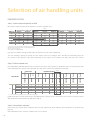
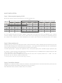
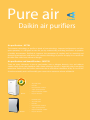
1
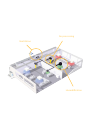
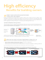
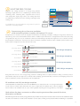
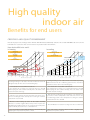
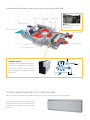
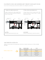
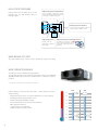
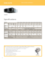
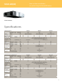
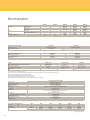
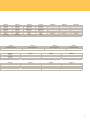
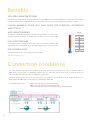
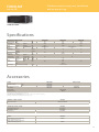
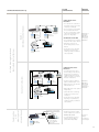
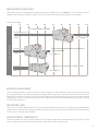
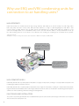
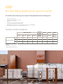
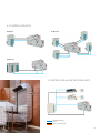
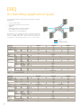
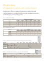
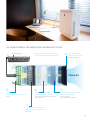
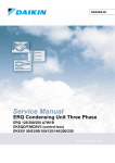
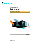
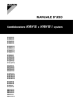
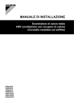
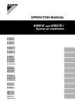
Freshen up your air ventilation catalogue Benefits for building owners Decreasing the energy costs of a building while, at the same time, maintaining or improving the air quality is our objective. We achieve this via high-efficiency heat recovery ventilation to reduce the loading on the air conditioning, combined with free cooling from the introduction of fresh outdoor air. Optional CO2 sensors to ensure that over-ventilation does not occur while maintaining indoor comfort high. end users High-quality air is essential for peak performance and pleasant environmental conditions. That means introducing fresh air with the correct level of humidity and necessary filtration to remove dust and other suspended particles which can cause respiratory issues or transmit odours. It also means ensuring the correct balance of CO2 and oxygen guaranteed by the optional CO2 sensors. design offices & consultants Part of the Daikin ‘Total Solution’, all components are supplied by Daikin thus ensuring seamless integration and maximum flexibility. The wide range of units, from large air handling units to small ventilation ensure there is a perfect solution to meet the individual customer’s needs. installers As a result of the compact designs and modular assembly, shorter installation times are the norm. And, since all components of the system are supplied by Daikin, installers can be certain that all components will and work seamlessly together, reducing overall installation and configuration time. Ventilation and air purification Daikin ventilation and air purification Fresh air is vital to our quality of life and well being. But as buildings become more airtight, fresh air circulation is much reduced. Daikin offers a variety of ventilation, air purification and large scale air handling solutions to help provide a fresh, healthy and comfortable environment in offices, hotels, stores and other commercial environments. Why we need fresh air in buildings As building regulations raise standards in the energy efficient design of buildings, insulation levels become much higher, reducing the heating and cooling demand in buildings. However, stale air can remain trapped and cause: • Need of oxygen • Greater risk of allergies • Odours lingering for longer • Increased condensation causing mould Ventilation Daikin commercial ventilation systems provide outdoor fresh air, remove stale air and balance the humidity within a building. This all helps to create a clean and comfortable environment that enhances the well-being of building users. Ventilation provides free cooling using fresh outside air. The option of heat recovery from within the building is also available to provide the highest levels of energy efficiency. Save energy with heat recovery The beauty of Daikin commercial ventilation systems is that they can use heat reclaimed from the stale air being extracted from buildings to heat the incoming clean air to a comfortable temperature. This reduces the load on the air conditioning system, delivering 40% energy savings compared with introducing unheated fresh air into a building. Integrated ventilation Ventilation can be integrated with Daikin’s cooling and heating systems, for simplified control of the entire system. By including ventilation as part of a complete climate control solution, it is possible to manage up to 50% of a building’s energy use - delivering huge potential savings in running costs and carbon emissions. 3 Which system offers me the best solution? Daikin offers a variety of solutions for the provision of fresh air ventilation to offices, hotels, stores and other commercial outlets – each one complementary to and as flexible as both Sky Air and VRV systems themselves. Heat Reclaim Ventilation Proper ventilation is a key component of climate control in buildings, offices and shops. In its basic function, it ensures a flow of incoming fresh air and outgoing stale air. Our HRV (heat reclaim ventilation) solution can do much more. It can recover heat and optimise the balance between indoor and outdoor temperature and humidity, thus reducing the load on the air conditioning system up to 40% and increasing efficiency. Outdoor Air Processing in a single unit Our FXMQ-MF air processing solution uses heat pump technology to combine fresh air treatment and air conditioning in a single system, thereby eliminating the usual design problems associated with balancing air supply and discharge. Total system cost is reduced and design flexibility enhanced because the indoor air conditioning fan coil units and an outdoor air treatment unit can be connected to the same refrigerant line. Daikin air handling units combined with condensing units For small, medium and large commercial spaces, we offer a range of R-410A inverter condensing units that connect plug & play to our air handling units. This approach combines the high efficiency of our ERQ and VRV units with the fully customisable Daikin air handling units, resulting in a simple, reliable design for optimum control of indoor air quality and maximum efficiency. AIR PURIFIERS Daikin air purifiers utilise the very latest technology to eliminate potentially harmful agents from the air. They deliver superior performance with silent operation, to improve indoor air quality and create a healthier environment. 4 Humidification overview ventilation range optimise the balance between indoor and outdoor humidity Ventilation Heat recovery provision of fresh air recovers heat and moisture from the outgoing air to maximise comfort & efficiency Air processing Filtration heats or cools incoming fresh air, maximising comfort and minimizing the load on the air conditioning installation Type name VAM-FA/FB Heat Reclaim Ventilation VKM-GB Components of indoor air quality Removes dust, pollution and odours from the air Air flow rate (m3/h) 0 200 400 600 800 1,000 1,500 2,000 4,000 6,000 8,000 124,000 ›› Ventilation ›› Heat recovery ›› Ventilation ›› Heat recovery ›› Air processing VKM-GBM ›› ›› ›› ›› Ventilation Heat recovery Air processing Humidification OUTDOOR AIR PROCESSING UNIT 1 FXMQ-MF ›› Ventilation ›› Air processing Air handling units DX total fresh air package ›› Ventilation ›› Heat recovery ›› Air processing ›› Humidification ›› Filtration MC70L Air purifiers MCK75J 1 2 3 (3) ›› Filtration ›› Filtration ›› Humidification Not connectable to VRVIII-S (RXYSQ-PAV, RXYSQ-PAY) Air flow rate is a calculated indication only, based on the following values: heating capacity EKEXV-kit * 200m³/h Daikin AHU connected to Daikin chiller solution 5 Table of contents Introduction24 ›› Benefits2 ›› Which system offers me the best solution? 4 ›› What's new? 7 HRV - Heat reclaim ventilation 8 ›› High efficiency - Benefits for building owners 10 ›› High quality indoor air - Benefits for end users 12 ›› Flexible installation - Benefits for design offices and consultants 15 ›› Benefits for installers 17 ›› Specifications 18 FXMQ-MF - Outdoor Air Processing Unit 22 ›› Benefits24 ›› Connection conditions 24 ›› Specifications 25 User friendly control systems 26 ›› Overview of control systems 28 ›› Individual control systems 30 ›› Centralised control systems 32 Daikin air handling units? 34 ›› Why use ERQ and VRV condensing units for connection to air handling units? 36 ›› Flexible control options 37 ›› VRV Air handling application (pair & multi) 38 ›› ERQ Air handling application (pair) 40 ›› Overview of expansion valves and control boxes 41 ›› Accessories42 ›› Selection of air handling units Pure air - Daikin air purifiers 44 46 ›› Air purification - MC70L 46 ›› Air purification and humidification - MCK75J 46 What’s new? All ventilation units fully eco design compliant From 01/01/2013 all ventilation units with a fan from 125 W to 500 kW have to comply to the LOT 11 Eco design requirements. As market leader Daikin takes the step to comply with all ventilation units to this by adopting DC fan motors in all ventilation units in scope of this legislation, improving their energy efficiency even further. HEAT RECLAIM VENTILATION VAM-FB - VKM-GB(M) • • • • Better efficiency with DC fan motor Optional CO2 sensor saves energy while maintaining comfort Optional M6, F7 and F8 dust filters (for VAM-FB series only) Shorter installation time thanks to easy adjustment of nominal air flow rate ELECTRICAL HEATER FOR VAM • • • • • • • Total solution for fresh air with Daikin supply of both VAM and electrical heater Increased comfort in low outdoor temperature thanks to the heated outdoor air Integrated electrical heater concept (no additional accessories required) Standard dual flow and temperature sensor Flexible setting with adjustable setpoint Increased safety with 2 cut-outs: manual & automatic BMS integration thanks to: • volt free relay for error indication • 0-10V DC input for setpoint control DAIKIN AIR HANDLING UNITS D-AHU PROFESSIONAL/EASY/ENERGY • • • • • Total solution with Daikin supply of R-410A inverter condensing units or Chillers Plug & play concept: factory mounted DDC controller, control box, expansion valve and all other components designed and configured for connecting Daikin ERQ or VRV condensing units Highly efficiency heat recovery AHU recovering up to 80% of heat Standard G4 filters and optional filters available up to class F7 5 pre-defined AHU packages (from 2,000 to 10,000m³/h) make selection quick and easy 7 HRV Heat reclaim ventilation Create a high quality indoor environment Energy saving ventilation using indoor heating, cooling and moisture recovery The Daikin HRV (Heat Reclaim Ventilation) unit recovers heat energy lost through ventilation and maintains a comfortable and clean indoor environment without changes in room temperature. This also reduces the load on the air conditioning system and produces up to 40% saving on energy when compared with introducing unheated fresh air into a building. In addition to the paper heat exchanger, the current HRV line-up includes models with or without a DX coil and/or humidifier. The DX coil helps to prevent cold draughts on people during the heating and cooling cycle. While the humidifier conditions the incoming fresh air to produce a comfortable indoor humidity level, even during heating. And the optional CO2 sensors will help maintain a comfortable indoor air quality, while preventing over-ventilation. In addition, the HRV can be locked into Daikin’s air conditioning systems (for example, the VRV and Sky Air) and set to automatically switch over to ventilation mode when needed, further increasing energy conservation. The HRV can also be integrated in the air conditioner remote control allowing total control over air conditioning and ventilation via a simple configuration. Integration Integrating the HRV with Daikin's Sky Air or VRV air conditioning produces a system that works perfectly together. The automatic controls ensure that the system always operates in the most optimal state. For example, free cooling via the ventilation will be applied where possible and not via the air conditioning. 8 Air processing Ventilation Humidification High efficiency Benefits for building owners Energy saving ventilation via heat recovery of both heat and humidity Buildings need ventilation, all year round. However, in traditional ventilation systems, conditioned air from the building is simply expelled, then new unheated air is brought into the building. So a large volume of air is heated up or cooled down unnecessarily, leading to a substantial waste of energy. Daikin’s HRV solutions prevent energy being wasted by recovering up to 80% waste heat from the outgoing air, thus offering much greater levels of efficiency, while improving comfort levels too. Specially developed heat exchange element The heat exchange element uses a high efficiency paper (HEP) possessing superior moisture absorption and humidifying properties. The heat exchange unit rapidly recovers heat contained in latent heat (vapour). The element is made of a material with flame resistant properties and is treated with an anti-moulding agent. Outdoor Operation of the high effiency paper. Indoor 30.6°C 62% RH Cross flow of air to exchange heat and moisture. 32°C 70% RH Integrally-formed liner SA 27.4°C 63% RH SA Integrallyformed liner RA Temperature and humidity is exhanged between the layers RA 26°C 50% RH Thanks to the heat and moisture exchange the hot and humid outside air is brought to levels close to indoor conditions saving on the air conditioning runningcost and maintaining comfort. RH: Relative Humidity SA: Supply Air (to room) RA: Return Air (from room) Reducing the load on the air conditioning system up to 31% Thanks to the use of heat reclaim ventilation the load on the air conditioning is reduced with approximately 31%. • • • 23% by operating in total heat exchange mode (in comparison with normal ventilation fans) another 6 % by auto-ventilation mode changeover switching a further 2 % by pre-cool, pre-heat control (reduces air conditioning load by not running the HRV shortly after the air conditioning is switched on.) Note: the values mentioned above may vary according to weather and other environmental conditions at the location of the unit’s installation Advantages of integration of ventilation and air conditioning (automatic change over) Air conditioning in cooling Heat exchanger Exhaust fan Damper element (heat recovery) Air conditioning in heating Heat exchanger element (heat recovery) Air conditioning off In between (bypass ventilation) EA RA EA RA OA SA OA SA Automatic changeover Air supply fan DX coil (cooling) RA EA Automatic changeover SA OA DX coil (heating) Humidifying EA: exhaust air RA: return air (from room) OA: outdoor air SA: supply air (to room) For VKM-GB(M) units 10 Nighttime free cooling Temp. Nighttime free cooling operation is an energy saving function operating at night when the air conditioning is switched off. By ventilating rooms containing office equipment that increases room temperature, night purge reduces the cooling load when air conditioning is switched on in the morning, reducing the daily running costs. 40 30 Setting Temp. Indoor Temp. 20 HRV The new VAM-FB series can also perform nighttime free cooling in stand alone operation. The set temperature is a field setting at installation. Outdoor Temp. 2 Hours auto on start off on start Air Conditioner off Prevent energy losses from over-ventilation while maintaining indoor air quality with optional CO2 sensor Enough fresh air is needed to create an enjoyable environment, but ventilating constantly is leading to energy waste. Therefore an optional CO2 sensor can be installed which switches off the ventilation system when there is enough fresh air in the room, thus saving energy. When the CO2 levels rise, the ventilation is switched on maintaining air quality at the highest level. As a customer you have the possibility to customize the critical CO2 levels when and how the ventilation should react (the ventilation system switches on by itself or shifts to a higher fan speed to lower the CO2 levels). Air handling unit 40% of design outside air 40% of exhaust air 20% of design outside air 20% of exhaust air 10% of design outside air 10% of exhaust air 100% of design outside air 100% of exhaust air CO2 sensor 3 Supply air 60% recirculated air Supply air 2 20% design occupancy 80% recirculated air Supply air 1 90% recirculated air Supply air 40% design occupancy Return air duct 0 0% design occupancy 100% design occupancy 0% recirculated air Using CO2sensors has the most energy-saving potential in buildings where occupancy fluctuates during a 24-hour period, is unpredictable and peaks at a high level. For example office buildings, government facilities, retail stores and shopping malls, movie theaters, auditoriums, schools, entertainment clubs and nightclubs. All ventilation units fully eco design compliant From 01/01/2013 all ventilation units from 125 W to 500 kW have to comply to the LOT 11 Eco design requirements on fan motors. As market leader Daikin takes the step to comply with all ventilation units to this by adopting DC fan motors in all ventilation units in scope of this legislation, improving their energy efficiency even further. Ideal solution for shops, restaurants or offices requiring maximum floor space for furniture, decorations and fittings Our HRV range of units are not only energy efficient, they also blend in any interior and leave all the maximum of usable floor space. The units are invisible to see and can be installed in service spaces, making service possible while the building is in operation. 11 High quality indoor air Benefits for end users Creating a high quality environment Next to the paper heat exchanger of the VAM the VKM-GB models additionally contain a DX-coil and VKM-GBM both a DX coil and humidifier. The result is the units can ensure the best possible indoor environment. How do the HRV units work? In heating In cooling 100 Heat recovery t(VAM, VKM-GB, VKM-GBM) 80 + 100 Heat recovery (VAM, VKM-GB, VKM-GBM) 60 Cooling (VKM-GB, VKM-GBM) + Effect of cooling 40 0 5 2 1 Effect of of heating Effect heating Effect of Effect of full full heat heat exchange exchange 10 15 20 25 Dry bulb temperature (°CDB) 30 Indoor temperature during cooling 20 20 Relative humidity (%) 3 40 35 40 Relative humidity (%) Effect of humidification Indoor temperature during heating 1 2 4 4 -5 Outdoor air temperature in summer Effect of full heat exchange Heating (VKM-GB, VKM-GBM) 60 + Humidifying (VKM-GBM) Outdoor air temperature in winter 80 -5 0 5 10 15 20 25 Dry bulb temperature (°CDB) 30 35 40 In cooling we bring in hot outdoor fresh air and want to prevent In heating we bring in cold outdoor fresh air and want to avoid cold additional load on the air conditioning system and too hot indoor draught and dry air. This is done in the following way: temperatures. This is done in the following way: 1. Cold outside air is crossed with hot inside air. In the example the incoming air is heated up from 0 to 16°CDB while keeping the same relative humidity. This is the effect of the heat and moisture exchange. 1. Hot outside air is crossed with cold inside air. In the example the incoming air is cooled down from 34 to 27°CDB while keeping the same relative humidity. This is the effect of the heat and moisture exchange. 2. After the heat exchange the DX coil further cools down the air 2. After the heat exchange the DX coil further heats up the air to to prevent hot indoor temperatures and reduce the load on the prevent cold draught. In the example the incoming air is further air conditioning system. In the example the incoming air is further heated from 16 to 34°CDB cooled down from 27 to 18°CDB 3. Because of the heating up of the air the relative humidity decreases. To counter negative effects of dry air the air passes the 3. No humidification is needed in cooling as the air is not dried out humidifier which adds moisture in case needed. In the example the relative humidity rises from 22 to a comfortable 42%. 4. The end result is incoming fresh air with the same humidity and 4. The end result is incoming fresh air with a slightly lower slightly higher temperature for perfect comfort. temperature for perfect comfort. 12 Operation of humidification and air processing in heating mode (VKM-GBM) Exhaust Fan EA (Exhaust air to outdours) Heat Exchanger Elements Damper Motor Damper DX coil for pre-heating and -cooling of incoming air OA (Fresh air from outdoors) RA (Return air from room) SA (Supply air to room) Air Supply Fan Electronics Box (Control box) Float switch Solenoid valve Humidifier element: Utilizing the principle of capillary action, water water is permeated throughout the humidifier AIRFLOW element. The heated air from the DX coil SA passes through the humidifier and absorbs the moisture. Drain pan Drain Optional medium and fine dust filters available M6, F7 and F8 filters are available on the VAM-FB models to meet your customer request or the local legislation. As one has no control of the air quality in the building surroundings, you can rely on one of our dust filters to ensure the best indoor air quality possible. 13 Can operate in over- and underpressure to prevent unpleasant odours The user can select 2 fresh-up modes via the remote control for a more comfortable air environment. 1. Supply rich mode (overpressure): 2. Exhaust fresh-up (underpressure): A higher air supply than air exhaust maintains proper room pressure to prevent back-flow of toilet/kitchen odours or moisture inflow. A higher exhaust air than air supply decreases room pressure to prevent the leaking of odours or floating bacteria into other rooms. Portion of fresh-up operation Air exhaust Normal ventilation fan HRV Air exhaust HRV 30% Air supply 100% Portion of exhaust operation 70% Hall way Air supply Sick room 70% 100% 30% eg. Office eg. Hospital Preventing that toilet odours flow to the office No bacteria can flow from the sick room to the hall way low operation sound level Continues research by Daikin into reducing operation sound levels has resulted in sound pressure levels down to 20.5dBA (VAM150FA). Daikin indoor units 14 DBA PERCEIVED LOUDNESS SOUND 0 Treshold of hearing - 20 Extremely soft Rustling leaves 40 Very soft Quiet room 60 Moderately loud Normal conversation 80 Very loud City traffic noise 100 Extremely loud Symphonic orchestra 120 Threshold of feeling Jet taking off 25 Benefits for design offices and consultants Total solution concept - integrated ventilation The integration of ventilation into a total building climate system, such as the VRV system, offers numerous advantages. Daikin supplies all components of the entire system, simplifying its design and presenting an ideal solution for the building itself and a ‘one-stop’ solution for the client. As well as design benefits, it also simplifies project follow-up, installation and subsequent commissioning and maintenance since only one party is involved. Finally, the end user benefits from ‘interlocking’ ventilation with air conditioner operation by virtue of greatly simplified overall system control. Note: more information on integrated control can be found in the control systems chapter. Flexible installation 285mm Slim Design The slim design of the HRV unit enables it to be mounted in narrow ceiling voids and irregularly shaped spaces. VAM250FA Installation under the floor of a small building Installation under a beam Installation in an irregular space Horizontal or vertical installation The VAM and VKM units can be installed horizontal in false ceilings for example. However if there are no false ceilings or the space is limited the unit can also be installed vertically in narrow service spaces or behind a wall. In this way the the consultant can focus fully on the design of the building. 15 High Static Pressure External static pressure (ESP) up to 137 Pa facilitates the use with flexible ducts of varying lengths. Higher static pressure and reduced noise The use of multiple, overlapping arc shaped fan blades makes it possible to optimize the chord lenght and blade outlet angle. Rotating currents for reduced loss The use of a thinner scroll allows rectification of rotating currents within the scroll. Higher static pressure Thanks to wide fan diameter and optimized blade width Higher static pressure and reduced pressure loss α In addition to increasing the scroll wrap angle and boosting the static pressure, the outflow angle has been optimized. θ Wide range of units The wide Daikin range ensures correct equipment design and sizing. Wide operation range The HRV unit can be installed practically anywhere. The standard operation range (outdoor temperature) is from -15°C to 40°CDB (50°CDB for VAM units) and can be extended down if a Daikin pre-heater is installed. 1 Contact your local dealer for more information and restrictions Daikin’s supplied electrical heater VH provides a total solution for fresh air and pre-heating. • • • • • Integrated electrical heater concept (no additional accessories required) Standard dual flow and temperature sensor Flexible setting with adjustable setpoint Increased safety with 2 cut-outs: manual & automatic BMS integration thanks to: - volt free relay or error indication - 0-10V DC input for setpoint control VAM VKM Cooling 50°CDB 50° Cooling 40°CDB 40° 30° 20° 10° -20° -15° CDB … 16 -15° CDB … with optional preheater -10° with optional preheater 0° Ensure the most efficient selection via the selection software The selection software Daikin supplies enables you to make the most optimum selection in the shortest possible time. The software proposes the best suited unit based upon the climate, building and applied ducting and proposes any needed accessories (electrical heater, …). Connection to field supplied booster fan increases flexibility even more The connection to a field supplied booster fan allows longer ducting from and away from the HRV unit or allows central ducting to reduce the installation time and space. Furthermore flexibility is also increased as different combinations of VAM units and booster fans allow the installation to be suited exactly to installation space, selected filters, comfort or sound requirements and energy use. Exhaust air Outdoor air Booster fan HRV UNIT Supply air Return air HRV UNIT HRV UNIT Benefits for installers Simple Design and Construction Switch box Access door Upside down installation Horizontal installation Maintenance cover The unit can be installed either horizontally or upside down always allowing easy access for inspection and maintenance. A 450 mm square inspection hatch enables maintenance and heat exchange element replacement to be performed with ease. No drain needed For the VAM-FA/FB models no drain piping is needed, meaning there additional flexibility for the installation of the units. 17 VAM-FA/FB Heat reclaim ventilation VAM800FB Specifications VENTILATION Power input 50Hz VAM150FA VAM250FA VAM350FB VAM500FB VAM650FB VAM800FB VAM1000FB VAM1500FB VAM2000FB Heat exchange mode Bypass mode Nom. Nom. Ultra high Ultra high Temperature Ultra high exchange efficiency - 50Hz Cooling Ultra high Enthalpy exchange Heating Ultra high efficiency - 50Hz Operation mode Heat exchange system Heat exchange element Dimensions Unit HeightxWidthxDepth Weight Unit Fan-Air flow rate Heat exchange Ultra high - 50Hz mode Bypass mode Ultra high Fan-External static Ultra high pressure - 50Hz Sound pressure Heat exchange Ultra high level - 50Hz mode Bypass mode Ultra high Operation range Min. Max. Relative humidity Connection duct diameter Power supply Phase/Frequency/Voltage Current Maximum fuse amps (MFA) kW kW % 0.116 0.141 0.132 0.178 0.196 0.373 0.375 0.828 0.852 0.116 0.141 0.132 0.178 0.196 0.373 0.375 0.828 0.852 74 72 75 % % mm kg m³/h m³/h Pa dBA dBA °CDB °CDB % mm Hz/V A 58 61 64 65 74 58 62 63 75 60 61 65 66 Heat exchange mode / Bypass mode / Fresh-up mode Air to air cross flow total heat (sensible + latent) exchange Specially processed non-flammable paper 301x828x816 364x1,004x868 364x1,004x1,156 33 52 55 64 285x776x525 24 726x1,512x868 131 726x1,512x1,156 152 150 250 350 500 650 800 1,000 1,500 2,000 150 250 350 500 650 800 1,000 1,500 2,000 93 137 69 64 27 / 28.5 28 / 29 32 33 34.5 36 39.5 40 27 / 28.5 28 / 29 32 33.5 34.5 -15 50 80% or less 200 1~/50/60/220-240/220 36 40.5 40 100 98 150 15 157 250 137 350 16 Total solution for fresh air with Daikin supply of both VAM and electrical heaters ›› ›› ›› ›› ›› ›› ›› 18 Increased comfort in low outdoor temperature thanks to the heated outdoor air Integrated electrical heater concept (no additional accessories required) Standard dual flow and temperature sensor Flexible setting with adjustable setpoint Increased safety with 2 cut-outs: manual & automatic BMS integration thanks to: •Volt free relay for error indication • 0-10V DC input for setpoint control Capacities ranging from 1 to 2.5 kW VH Electrical heater for VAM VKM-GB(M) Heat reclaim ventilation, air processing and humidification VKM80-100GB(M) Specifications VENTILATION & DX COIL Heat exchange mode Nom. Ultra high Power input - 50Hz Ultra high Bypass mode Nom. Fresh air Cooling conditioning load Heating Temperature exchange efficiency Ultra high - 50Hz Enthalpy exchange Cooling Ultra high Ultra high efficiency - 50Hz Heating Operation mode Heat exchange system Heat exchange element HeightxWidthxDepth Dimensions Unit Weight Unit Fan-Air flow rate Heat exchange mode Ultra high Bypass mode Ultra high - 50Hz Fan-External static Ultra high pressure - 50Hz Sound pressure Heat exchange mode Ultra high Bypass mode Ultra high level - 50Hz Around unit Operation range Supply air Return air Refrigerant Type Connection duct diameter Liquid OD Piping connections Gas OD Drain Power supply Phase/Frequency/Voltage Current Maximum fuse amps (MFA) VENTILATION, DX COIL & HUMIDIFICATION Heat exchange mode Nom. Ultra high Power input - 50Hz Bypass mode Nom. Ultra high Fresh air Cooling conditioning load Heating Temperature exchange efficiency Ultra high - 50Hz Enthalpy exchange Cooling Ultra high Ultra high efficiency - 50Hz Heating Operation mode Heat exchange system Heat exchange element Humidifier System Dimensions Unit HeightxWidthxDepth Weight Unit Fan-Air flow rate Heat exchange mode Ultra high Bypass mode Ultra high - 50Hz Fan-External static Ultra high pressure - 50Hz Sound pressure Heat exchange mode Ultra high Bypass mode Ultra high level - 50Hz Around unit Operation range Supply air Return air Refrigerant Type Connection duct diameter Liquid OD Piping Gas OD Water supply connections Drain Power supply Phase/Frequency/Voltage Current Maximum fuse amps (MFA) kW kW kW kW VKM50GB 0.270 0.270 4.71 (1) / 1.91 (2) / 3.5 (3) 5.58 (1) / 2.38 (2) / 3.5 (3) % % % mm kg m³/h m³/h VKM80GB 0.330 0.330 7.46 (1) / 2.96 (2) / 5.6 (3) 8.79 (1) / 3.79 (2) / 5.6 (3) VKM100GB 0.410 0.410 9.12 (1) / 3.52 (2) / 7.0 (3) 10.69 (1) / 4.39 (2) / 7.0 (3) 76 78 74 64 67 66 71 Heat exchange mode / Bypass mode / Fresh-up mode Air to air cross flow total heat (sensible + latent) exchange Specially processed non-flammable paper 387x1,764x1,214 110 750 750 62 65 387x1,764x832 94 500 500 Pa 210 dBA dBA °CDB °CDB °CDB 39 40 mm mm mm 200 Hz/V A kW kW kW kW VKM50GBM 0.270 0.270 4.71 (1) / 1.91 (2) / 3.5 (3) 5.58 (1) / 2.38 (2) / 3.5 (3) 112 950 950 150 41.5 41.5 0°C~40°CDB, 80% RH or less -15°C~40°CDB, 80% RH or less 0°C~40°CDB, 80% RH or less 6.35 12.7 PT3/4 external thread 1~/50/220-240 15 41 41 250 VKM80GBM 0.330 0.330 7.46 (1) / 2.96 (2) / 5.6 (3) 8.79 (1) / 3.79 (2) / 5.6 (3) VKM100GBM 0.410 0.410 9.12 (1) / 3.52 (2) / 7.0 (3) 10.69 (1) / 4.39 (2) / 7.0 (3) % 76 78 74 % % 64 67 62 65 387x1,764x832 100 500 500 66 71 Heat exchange mode / Bypass mode / Fresh-up mode Air to air cross flow total heat (sensible + latent ) exchange Specially processed non-flammable paper Natural evaporating type 387x1,764x1,214 119 750 750 123 950 950 Pa 200 205 110 dBA dBA °CDB °CDB °CDB 38 39 mm mm mm mm 200 mm kg m³/h m³/h Hz/V A 0°C~40°CDB, 80% RH or less -15°C~40°CDB, 80% RH or less 0°C~40°CDB, 80% RH or less R-410A 6.35 12.7 6.4 PT3/4 external thread 1~/50/220-240 15 40 41 250 19 Accessories Dust filters Silencer VAM150FA VAM250FA VAM350FB VAM500FB VAM650FB EN779 Medium M6 - - EKAFV50F6 EKAFV50F6 EKAFV80F6 EN779 Fine F7 - - EKAFV50F7 EKAFV50F7 EKAFV80F7 EN779 Fine F8 - - EKAFV50F8 EKAFV50F8 EKAFV80F8 Model name - - - KDDM24B50 KDDM24B100 Nominal pipe Diameter (mm) - - - 200 200 - - BRYMA65 BRYMA65 BRYMA65 VH1B VH2B VH2B VH3B VH3B CO2 sensor VH electrical heater for VAM INDIVIDUAL CONTROL SYSTEMS Wired remote control VAM-FA/FB VKM-GB(M) BRC1E52A/B / BRC1D52 BRC1E52A/B / BRC1D52 BRC301B61 - VAM wired remote control CENTRALISED CONTROL SYSTEMS VAM-FA/FB VKM-GB(M) Centralised remote control DCS302C51 DCS302C51 Unified ON/OFF control DCS301B51 DCS301B51 Schedule timer DST301B51 DST301B51 OTHERS VAM150-250FA VAM350-2000FB Wiring adaptor for electrical appendices (note 6) KRP2A51 (note 3) tbc tbc Adaptor PCB for humidifier KRP50-2 (note 3) BRP4A50A (note 4/5) BRP4A50A (note 4/5) BRP4A50 BRP4A50A (note 4/5) BRP4A50A (note 4/5) - - - Adaptor PCB for 3rd party heater Remote sensor VKM-GB(M) Notes (1) Cool/heat selector required for operation (2) Do not connect the system to DIII-net devices (Intelligent controller, Intelligent Manager, LonWorks interface, BACnet interface…). (3) Installation box KRP50-2A90 needed for VAM150-250FA. (4) Fixing plate EKMPVAM additionally needed for VAM1500-2000FB. (5) 3rd party heater and 3rd party humidifier cannot be combined (6) For external control and monitoring (ON/OFF control, operation signal, error indication) VH electrical heater for VAM Supply voltage Output current (maximum) Temperature sensor Temperature control range Run on timer Control fuse 220/250V ac 50/60 Hz. +/-10% 19A at 40°C (ambient) 5k ohms at 25°C (table 502 1T) 0 to 40°C / (0-10V 0-100%) Adjustable from 1 to 2 minutes (factory set at 1.5 minutes) 20 X5 mm 250 m A LED indicators Power ON - Yellow Heater ON - Red (solid or flashing, indicating pulsed control) Airflow fault - Red Mounting holes Maximum ambient adjacent to terminal box Auto high temp. cutout Man. reset high temp. cutout Run relay BMS setpoint input VH electrical heater for VAM Capacity kW Duct diameter mm Connectable VAM 98mm X 181mm centres 5 mm ø holes 35°C (during operation) 100°C Pre-set 125°C Pre-set 1A 120V AC or 1A 24V DC 0-10VDC VH1B 1 100 VAM150FA - VH2B 1 150 VAM250FA VAM350FB VH3B 1 200 VAM500FB VAM650FB VH4B 1.5 250 VAM800FB VAM1000FB VH4/AB 2.5 250 VAM800FB VAM1000FB VH5B 2.5 350 VAM1500FB VAM2000FB preliminary information 20 VAM800FB VAM1000FB VAM1500FB VAM2000FB VKM50GB(M) VKM80GB(M) VKM100GB(M) EKAFV80F6 EKAFV100F6 EKAFV100F6 x2 EKAFV100F6 x2 - - - EKAFV80F7 EKAFV100F7 EKAFV100F7 x2 EKAFV100F7 x2 - - - EKAFV80F8 EKAFV100F8 EKAFV100F8 x2 EKAFV100F8 x2 - - - KDDM24B100 KDDM24B100 KDDM24B100 x2 KDDM24B100 x2 - - - 250 250 250 250 - - - BRYMA100 BRYMA100 BRYMA200 BRYMA200 BRYMA65 BRYMA100 BRYMA200 VH4B / VH4/AB VH4B / VH4/AB VH5B VH5B - - - FXMQ-MF EKEQFCB 2 EKEQDCB 2 EKEQMCB 2 BRC1E52A/B / BRC1D52 BRC1E52A/B / BRC1D52 BRC1E52A/B / BRC1D52 1 BRC1E52A/B / BRC1D52 1 - - - - FXMQ-MF EKEQFCB 2 EKEQDCB 2 EKEQMCB 2 DCS302C51 - - - DCS301B51 - - - DST301B51 - - - FXMQ-MF EKEQFCB 2 EKEQDCB 2 EKEQMCB 2 - - - - - - - - - - - - KRCS01-1 21 FXMQ-MF Outdoor Air Processing Unit Combined fresh air treatment and air conditioning via a single system Both fresh air treatment and air conditioning can be achieved successfully in a single system via heat pump technology. This without the usual design problems associated with balancing air supply and discharge. Air conditioning indoor units and an outdoor air processing units can be connected to the same refrigerant circuit, resulting in enhanced design flexibility and a significant reduction in total system costs. 22 Ventilation & air processing Benefits 100% Fresh Air Intake Possible Outdoor air processing units can be used exclusively to provide 100% fresh air into the building. Even if only partly used the system reduces the load on the air conditioner by adjusting the outdoor air temperature via fixed discharge temperature control. Leaving maximum floor and wall space for Furniture, decoration and fittings Wide operation range FXMQ-MF The outdoor air processing unit can be installed practically anywhere. The unit operates at outdoor ambients up to 43°C in cooling mode and down to -5°C in heating mode. 50° High static pressure 30° External static pressure (ESP) up to 225 Pa allows the use of extensive ductwork runs and facilitates the use with flexible ducts of varying lengths. Ideal for use in large areas. 20° 43°C 40° 10° 0° Built-in drain pump -5°C -10° A drain pump kit increases the reliability of the drain system 1 1 Drain pump kit available as accessory Connection conditions ›› The total connected capacity of the standard indoor units and fresh air treatment units must be between 50% and 100% of the capacity of the air conditioning outdoor units. The connected capacity of the fresh air treatment units must not exceed 30% of the capacity of the air conditioning outdoor units. ›› A fresh air treatment unit can also be used exclusively. The connected capacity of the fresh air treatment unit must be between 50% and 100% of the capacity of the air conditioning outdoor unit. ›› Connectable outdoor units: - VRVIII Heat pump Optimised for heating (RTSYQ) - VRVIII Heat pump High COP combination (RXYHQ) - VRVIII Heat pump Small footprint combination (except 5HP unit) (RXYQ) 20HP VRV III Series Outdoor Units Outdoor Air processing Unit Indoor Unit Indoor Unit 3x 5HP Indoor Unit Outdoor Air Processing unit 5HP Air Conditioning 24 Outdoor Air Supply FXMQ-MF Specifications Outdoor air processing unit, ventilation and air processing 125, 200, 250 FXMQ200-250MF Specifications VENTILATION & AIR PROCESSING Cooling capacity Nom. Heating capacity Nom. Power Input Cooling (50Hz) Heating Dimensions Unit Weight Unit Air Flow Rate Cooling Heating External Static Pressure Standard Refrigerant Type Sound Power Cooling Sound Pressure Cooling Operation range On coil temperature Piping connections Power supply Nominal Nominal HeightxWidthxDepth Nominal Nominal (220V) Cooling max. Heating min. OD OD Liquid Gas Drain Phase / Frequency / Voltage kW kW kW kW mm kg m3/min m3/min Pa dBA dBA °CDB °CDB mm mm FXMQ125MF 14.0 8.9 0.359 0.359 470x744x1,100 86 18 185 FXMQ200MF 22.4 13.9 0.548 0.548 FXMQ250MF 28.0 17.4 0.638 0.638 470x1,380x1,100 123 28 225 R-410A - 42 35 205 47 43 -5 9.52 19.1 PS1B 1~ / 50 / 220-240 15.9 Hz / V 22.2 Accessories OTHERS High efficiency filter -65% -90% Replacement long life filter Filter chamber 1 Drain pump kit Adapter for wiring FXMQ125MF FXMQ200-250MF KAFJ372L140 KAFJ373L140 KAFJ371L140 KDJ370SL140 KAFJ371L280 KDJ370SL280 KDU30LL250VE KRP1B61 (1) Filter chamber has a suction-type flange. (Main unit does not). Some options may not be usable due to the equipment installations conditions. Please conrfirm prior to ordering. Some options may not be used in combination. Operating sound may increase somewhat depending on the options used. INDIVIDUAL CONTROL SYSTEMS Wired remote control FXMQ-MF BRC1E52A / BRC1D52 CENTRALISED CONTROL SYSTEMS FXMQ-MF Centralised remote control DCS302C51 Unified ON/OFF control DCS301B51 Schedule timer DST301B51 OTHERS FXMQ-MF Wiring adapter for electrical appendices (control and monitoring F1 F2) KRP2A61 Wiring adapter for electrical appendices (control and monitoring P1 P2) KRP4A51 25 User friendly control systems 26 interlock of the ventilation operation with the air conditioner operation Interlock of the ventilation operation with the air conditioner operation greatly simplifies overall system control. The same remote control centralizes air conditioning and ventilation. Using a centralized remote control also frees the user to choose from a wide range of control systems that integrate air conditioning and ventilation. By incorporating a variety of centralized control equipment, the user can build a large, high grade centralized control system. Linked control of FXMQ-MF and HRV is not supported 1 VRV indoor unit ›› ›› ›› ›› ›› ›› Operating mode signal ›› Filter cleaning signal ›› Faillure detection signal ON/OFF signal Cooling/Heating mode signal Set temperature signal Ventilation signal Humidifier ON/OFF signal HRV Interlocking “Super Wiring” System A Super Wiring system is used to enable the shared use of wiring between indoor units, outdoor units and the centralised remote control. This system makes it easy for the user to retrofit the existing system with a centralised remote control, simply by connecting it to the outdoor units. Thanks to a non polarity wiring system, incorrect connections become impossible and installation time is reduced. Indoor unit VKM Wired remote control Outdoor unit 27 Overview of control systems Individual Control Systems 5 individual control systems give the user control over the VRV system and the combined ventilation. ›› BRC1D52 and BRC1E52A/B are wired remote controllers, giving access to room temperature settings, schedule timer, … Next to that they also have user friendly HRV functions. ›› BRC301B61 is a wired controller especially designed for VAM units. ›› BRC2C51 and BRC3A61 are compact, easy to use remote controllers, ideal for use in hotel bedrooms. VAM remote control BRC301B61 Wired remote control BRC1E52A/B Wired remote control BRC1D52 Centralised control systems By combining the (optional) centralised control equipment listed below, the user can achieve a wide range of comprehensive centralised control systems for air conditioning and ventilation. Centralised remote control DCS302C51 28 Unified ON/OFF control DCS301B51 Schedule timer DST301B51 Network solutions HRV and the Outdoor Air Processing unit are connectable to all current Daikin network solutions: DTA113B51 Basic solution for control (Sky Air and VRV). DCS601C51 Allows detailed and easy monitoring and operation of VRV systems (maximum 2 x 64 control groups). DCM601A51 The ideal solution for full control and management of maximum 1,024 VRV indoor units. DMS504B51 Open network integration of VRV monitoring and control functions into LonWorks networks. LonWorks Interface DMS502A51 Integrated control system for seamless connection between VRV and BMS systems. BACnet Interface For more information consult the Daikin controls systems brochure or contact your local dealer 29 Individual ›› ›› ›› ›› ›› ›› ›› ›› ›› ›› ›› ›› ›› control systems Control up to 16 indoor units or 8 HRV units (1group) Easy to use: all main functions directly accessible Easy setup: improved graphical user interface for advanced menu settings Simultaneous ON/OFF of HRV and air conditioner (BRC1D52/BRC1E52A/B) Airflow rate switching (initial setting) Ventilation mode switching (initial setting) Self diagnostic functions Filter sign display and reset Timer settings, simultaneous control with air conditioner (BRC1D52/BRC1E52A/B) ON/OFF of VAM (BRC301B61) Independent operation of HRV Timer settings (BRC301B61) Fresh-up mode switching (HRV only) (Selectable: supply rich mode, exhaust rich mode; initial setting) Notes: The remote control wired to the FXMQ-MF cannot be set as master remote control. Otherwise, when set to ‘auto’, the operation mode will switch according to outdoor air conditions, regardless of indoor temperature. BRC1E52A/B 30 BRC1D52 BRC301B61 A variety of units can be controlled using only the BRC1D52 or the BRC1E51A (HRV only) ›› Group Control One air conditioner remote control simultaneously controls up to 16 air conditioning and HRV units. ›› Control using 2 remote controls Allows control of air conditioning and HRV units from two locations by connecting two air conditioner remote controls. (group control is possible) ›› Long-distance Remote Control Remote operation control - from a distant control room for example - is possible thanks to wiring of up to 500 m. (2 remote controllers possible) Indoor units Long distance remote control Up to 500m HRV Control using 2 remote controls Up to 500m Group control BRC1E52A/B no2 BRC1E52A/B no1 *1: Count VKM unit as two air conditioner indoor units. For details, see below. System Characteristics HRV Operation system Independent System construction (hrv only) HRV BRC1D52 BRC1E52A/B BRC301B61* BRC1D52 BRC1E52A/B BRC301B61 * Standard system BRC1D52 BRC1E52A/B During group control operation, the VKM unit has a capacity equivalent to 2 standard indoor units. Up to 16 standard indoor units can be connected at the same time. Connectable indoor units: VKM 012345678 Max. no. of VRV 161412108 6 4 20 ›› Multiple VRV indoor units or HRV units can be connected and controlled in batches, with interlocked operation of HRV and air conditioners by using the air conditioner remote control. ›› The HRV unit can also be operated independently using the remote control for the indoor unit, even if the indoor unit is not in operation BRC1D52 or BRC1E52A/B Note: The VKM uses 2 remote controller addresses per unit. The number of units that can be group controlled is shown above. Group 1 Group 1 Operation system Multiple groups interlocked (VRV, Sky Air) system BRC1D52 or BRC1E52A/B BRC301B61 * HRV Indoor unit Air conditioning interlocked control ›› Independent operation of HRV is possible ›› Operation is possible using 2 remote controls ›› Multiple HRV units can be simultaneously controlled in batch. (Up to 8 HRV units can be connected) ›› Air conditioner remote control can be used Necessary Accessories Group 1 Indoor unit Group 2 Group 2 Indoor unit BRC1D52 BRC1E52A/B BRC1D52 BRC1E52A/B Indoor unit Indoor unit BRC1D52 BRC1E52A/B HRV Group 2 ›› Can control interlocked operation of multiple groups of VRV or Sky Air indoor units ›› When one of the multiple groups operates, HRV units are interlocked and operate simultaneously BRC1D52 or BRC1E52A/B BRC1D52 BRC1E52A/B HRV * BRC301B61 only available for VAM-FA/FB 31 Centralised control systems By combining the (optional) centralised control equipment listed below, the user can achieve a wide range of comprehensive centralised control systems for air conditioning and ventilation. DCS302C51 Centralised remote control - DCS302C51 ›› ›› ›› ›› ›› ›› ›› ›› DCS301B51 ›› ›› A maximum of 64 groups (128 indoor units, max. 10 outdoor units) can be controlled A maximum of 128 groups (128 indoor units, max. 10 outdoor units) can be controlled via 2 centralised remote controls in separate locations Group control (up and down buttons are added for group selection) Zone control Malfunction code display Max. wiring length 1,000 m (total : 2,000 m) Combination with unified ON/OFF control, schedule timer and BMS system Airflow volume and direction can be controlled individually for indoor units in each group operation. Ventilation volume and mode can be controlled for Heat Reclaim Ventilation (VKM). Up to 4 ‘operation/stop’ pairs can be set per day by connecting a schedule timer. Unified on/off control - DCS301B51 Providing simultaneous and individual control on 16 groups of indoor units ›› A maximum of 16 groups (128 air conditioning indoor and HRV units) can be controlled ›› 2 remote controls in separate locations can be used ›› Centralised control indication ›› Maximum wiring length of 1,000m (total: 2,000m) DST301B51 Schedule timer - DST301B51 Enabling 64 groups to be programmed ›› A maximum of 128 air conditioning indoor and HRV units can be controlled ›› 8 types of weekly schedule ›› A maximum of 48 hours back-up power supply ›› Maximum wiring length of 1,000m (total: 2,000m) Number of HRV units that can be connected per system Centralised remote control Unified on/off control Schedule timer Note: 32 2 units 8 units 1 unit ›› Group control is not possible between FXMQ-MF and standard type indoor units. Connect remote controllers to each unit. ›› Not all FXMQ-MF functions are available when using centralised control. Please refer to your local installer for detailed information. ›› The remote control wired to the FXMQ-MF cannot be set as master remote control. Otherwise, when set to ‘auto’, the operation mode will switch according to outdoor air conditions, regardless of indoor temperature. ›› Temperature setting and PPD are not possible, even when Intelligent Touch Controller or Intelligent Manager are installed. SYSTEM CHARACTERISTICS SYSTEM CONSTRUCTION (HRV only) NECESSARY ACCESSORIES Unified on/off control DCS301B51 HRV Indoor unit BRC1D52 BRC1E52A/B DCS301B51 DST301B51 BRC1D52 BRC1E52A/B ›› Up to 8 controllers can be installed in one centralised transmission line (in one system), which enables control of up to 128 groups. (16 groups x 8 = 128 groups) Schedule timer - DST301B51 ›› One schedule timer can control the weekly sche-dule of up to 128 units Indoor unit ›› Control system can be expanded depending on its purposes by combining a variety of centralised control equipment BRC1D52 BRC1E52A/B Centralised Control System DCS301B51 or DST301B51, BRC1D52 or BRC1E52A/B If necessary: DCS302C51 ›› HRV remote control can set the individual operation of each HRV unit HRV Zone 1 Indoor unit DCS302C51 HRV BRC1D52 BRC1E52A/B BRC1D52 BRC1E52A/B air conditioners ›› The centralised remote control provides settings and monitoring functions and can control up to 128 VRV and HRV units. A special adapter is required to connect Sky Air to the centralised line. ›› Control is possible in 3 different patterns: individual, batch or zone ›› Multiple groups can be controlled within the same zone Zone 2 Zone Control System Centralised remote control DCS302C51 ›› Multiple HRV units can be operated independently Indoor unit HRV DCS302C51, BRC1D52 or BRC1E52A/B If necessary: DSC301B51 or DST301B51 ›› System without air condi-tioning or HRV remote controls can be constructed BRC1D52 BRC1E52A/B Combination with other types of Air Conditioning Interlocked Batch / Individual Control System ›› One controller can control the on/ off operation of 16 groups of units collectively or individually ›› Control system can be expanded depending on requirements by combining a variety of centralised control systems No-voltage a-contact signal Adapter HRV Air conditioner BRC1D52 BRC1E52A/B Connecting line can be extended up to 50m ›› Simultaneous operation of HRVs and air conditioners is possible via BRC1D52/ BRC1E52A/B ›› Use of the HRV remote control enables to change settings or operate HRVs independently Connection adapter (no-voltage-acontact-signal) 33 air handling units Daikin For small to large commercial spaces Daikin offers a range of R-410A inverter condensing units for use in conjunction with air handling units. In situations where Daikin commercial range ventilation units cannot satisfy the ventilation requirement due to building constraints (large atriums, banquet halls etc), air handling units represent the ideal solution. Air handling units provide large fresh air volumes (>1,000 m/h) and high ESPs enabling the use of extensive ductwork runs. An air handler or air handling unit provides a tailor-made solution for optimising air conditions throughout multiple spaces. An air handler can be customised to your building - with no installation restrictions or design limitations - as air handler units are based on a completely unique modular design, so they can be sized (in increments of 1cm) to your exact requirements. ASTRA is the powerful software that Daikin has developed to offer a quick and comprehensive service for the customer in order to make the technical choice and the economic valorization of each AHU. It is a complete tool that can configure any type of product and respond exactly to the strictest design needs. The result is a comprehensive economic offer including all the technical data and drawings, the psychrometric diagram with the relative air treatment and the fans’ performance curves. The ASTRA software features a specific DX heat pump coil section able to calculate cooling and heating performances with the automatic selection of the appropriate Daikin expansion valve. Wide range of air flows Daikin’s wide range of air handling systems handle air flow rates from 500 m³/h up to 140,000 m³/h. The air handler unit can be adapted to deliver whatever air flow you require, via the specific dimensions of flow section available at the installation. Air flow (m3/h * 1000) 0 15 30 45 60 75 90 105 120 135 The most flexible solution D-AHU Professional Daikin AHU Range 1,100 m3/h D-AHU Energy 1,500 m3/h D-AHU Easy 500 m3/h up to 140,000 m3/h Best seasonal performance and return on investment up to 70,000 m3/h Ideal to cover your basic AHU needs up to 30,000 m3/h Return on investment The air handling unit (AHU) is critical to an effective climate control system and, although the initial investment can appear high, the savings generated by our advanced designs and operating efficiencies guarantee a rapid return on the investment made. Our AHU Energy series has been designed to deliver exceptional performance thus driving down the energy consumed and so lowering energy bills. Taken over the expected 15-year life-span of the equipment, this will result in a substantial saving, especially in a time of ever increasing energy prices. Pre-defined sizes 27 fixed sizes are available, optimized to reach the best compromise between competitiveness and manufacturing standardisation.. However Daikin’s section by section design means that units can be sized by 1cm increments and assembled on site, without welding, to suit the space constraints of the installation. High efficiency components All Daikin air handlers have been designed for optimum energy efficiency. Polyurethane or Mineral wool panels guarantee excellent thermal insulation performance. Filters are provided with a large choice of efficiency filtration class. 35 Why use ERQ and VRV condensing units for connection to air handling units? High Efficiency Daikin heat pumps are renowned for their high energy efficiency with COPs up to 4.56 in heating1. The VRV range offers both heat pump and heat recovery units with part load efficiencies as high as 9.02 Integrating the AHU with a heat recovery system is highly effective since an office system can frequently be in cooling mode while the outdoor air is too cold to be brought inside in an unconditioned state. In this case heat from the offices is merely transferred to heat up the cold incoming fresh air. In the absence of an AHU this ‘free heating’ the incoming fresh air would not be possible. 1 ERQ100AV1 heat pump 2 REYQ8P8 50% cooling - 50% heating load. Conditions: outdoor temperature 11°CDB, indoor temperature 18°CWB, 22°CDB Outside air = 10°C Fresh air supplied at 21°C. The temperature difference with the outdoor air is heated up for free by heat recovery via A/C system Indoor temperature 22°C, needs cooling because of solar radiation. The excessive heat can be transferred to the AHU High Comfort Levels Daikin ERQ and VRV units respond rapidly to fluctuations in supply air temperature, resulting in a steady indoor temperature and resultant high comfort levels for the end user. Daikin ERQ and VRV units respond rapidly to fluctuations in the supply air temperature, resulting in a steady indoor temperature, together with the dehumidification this results in high comfort levels for the end user. The ultimate is the VRV range which improves comfort even more by offering continuous heating, also during defrost. Easy Design and Installation The system is easy to design and install since no additional water systems such as boilers, tanks and gas connections etc are required. This also reduces the total system cost. 36 Flexible control options In order to maximize installation flexibility, 3 types of control systems are offered. Control x: Control of air temperature (discharge temperature, suction temperature, room temperature) via external device (DDC controller) Control y: Control of evaporating temperature via Daikin control (no DDC controller needed) Control z: Control of air temperature (suction temperature, room temperature) via Daikin control (no DDC controller needed) In order to maximise installation flexibility, 3 types of control systems are offered: Possibility X (Td/Tr control): Air temperature control via DDC controller Room temperature is controlled as a function of the air handling unit suction or discharge air (customer selection). The DDC controller is translating the temperature difference between set point and air suction temperature (or air discharge temperature or room temperature) into a reference voltage (0-10V) which is transferred to the Daikin control box (EKEQFCBA). This reference voltage will be used as the main input value for the compressor frequency control. Ts DDC Possibility Y (Te/Tc control): By fixed evaporating temperature A fixed target evaporating temperature of between 3°C and 8°C can be set by the customer. In this case, room temperature is only indirectly controlled. The cooling load is determined from the actual evaporating temperature (i.e. load to the heat exchanger). A Daikin wired remote controller (BRC1D52 or BRC1E52A/B - optional) can be connected for error indication. Te Td AHU Daikin control box: EKEQFCB TR Ts Daikin control box: EKEQFCB Te AHU TR Room Td Room BRC1D52 BRC1E52A/B ON / OFF Possibility Z (TS/Tr control): Using Daikin wired remote controller (BRC1D52 or BRC1E52A/B - optional) Set point can be fixed via standard Daikin wired remote controller. Remote ON/OFF can be achieved by an optional adapter KRP4A51. No external DDC controller should be connected. The cooling load is determined from the air suction temperature and set point on the Daikin controller. OPTION KIT Possibility x EKEQFCB Possibility y Possibility z KRP4A51 Ts Daikin control box: EKEQDCB EKEQMCB Te Td AHU TR Room BRC1D52 BRC1E52A/B Ts Td Tr Te AHU DDC = Air suction temperature = Air discharge temperature = Room temperature = Evaporating temperature = Air Handling Unit = Digital Display Controller FEATURES DDC controller is required Temperature control using air suction or air discharge temperature Using fixed evaporating temperature, no set point can be set using remote controller EKEQDCB EKFQMCB* Using Daikin wired remote controller BRC1D52 or BRC1E52A/B Temperature control using air suction temperature * EKEQMCB (for ’multi’ application) 37 VRV Air handling application (pair & multi) A R-410A inverter condensing units range for multi application with air handling units. ›› ›› ›› ›› ›› ›› ›› ›› Inverter controlled units Large capacity range (from 8 to 54HP) Heat recovery, heat pump R-410A Control of room temperature via Daikin control Large range of expansion valve kits available BRC1E52A/B is used to set the set point temperature (connected to the EKEQMCB). Connectable to all VRV heat recovery and heat pump systems Different control possibilities VRV III heat VRV III-S recovery REYHQ-P8/P9 RXYSQ-PAV R*YQ8-10T R*YQ12-30T R*YQ32-50T R*YQ52-54T REYHQ-P RXYSQ-PAY REYAQ-P VRV IV heat pump Control possibilities VRV-WIII RTSYQ-PA RWEYQ-P RWEYQ-PR X P P1 P2 - - - - - Y P P1 P2 - - - - - Z M M M M M M M M P = pair M = multi 1 By use of split coil (interlaced) 2 Separate coil per outdoor unit 38 VRV III-C X,Y control for VRV IV R*YQ8-10T R*YQ32-50T R*YQ12-30T Z control for all VRV outdoor units Refrigerant piping F1-F2 other communication 39 ERQ Air handling application (pair) A range of R-410A inverter condensing units for pair application with air handling units. ›› ›› ›› ›› ›› ›› Daikin air handling unit Inverter controlled units Large capacity range (from 100 to 250 class) Heat pump R-410A Wide range of expansion valve kits available Up to 5 ERQ units can be connected to an interlaced coil in one air handling unit The “Daikin Fresh Air Package” provides a complete Plug & Play Solution including AHU, ERQ or VRV Condensing Unit and all unit control (EKEQ, EKEX, DDC controller) factory mounted and configured. The easiest solution with only one point of contact. F1 - F2 Refrigerant piping VENTILATION Capacity range Cooling capacity Heating capacity Power input Nom. Nom. Cooling Heating EER COP Dimensions Weight Fan-Air flow rate Power supply Current VENTILATION Capacity range Cooling capacity Heating capacity Power input EER COP Dimensions Weight Fan-Air flow rate Power supply Current 40 ERQ125AV1 5 14.0 16.0 3.51 3.86 ERQ140AV1 6 15.5 18.0 4.53 4.57 3.42 3.94 3.99 HeightxWidthxDepth Nom. Nom. Nom. Nom. Nom. Min./Max. Min./Max. Heating Min. Cooling Max. mm kg m³/min m³/min dBA dBA dBA °CDB °CWB °CDB °CDB Type Liquid OD Gas OD Drain OD Phase/Frequency/Voltage Maximum fuse amps (MFA) mm mm mm Hz/V A Nom. Nom. Cooling Heating HP kW kW kW kW Unit Unit Cooling Heating Sound power level Nom. Sound pressure level Nom. Operation range Cooling Heating On coil temperature Refrigerant Piping connections ERQ100AV1 4 11.2 12.5 2.81 2.74 4.56 Unit Unit Cooling Heating Sound power level Cooling Sound pressure Cooling level Heating Operation range Cooling Heating On coil temperature Refrigerant Piping connections Nom. Nom. HP kW kW kW kW Nom. Nom. HeightxWidthxDepth Nom. Nom. Min./Max. Min./Max. Heating Min. Cooling Max. Type Liquid OD Gas OD Phase/Frequency/Voltage Maximum fuse amps (MFA) mm kg m³/min m³/min dBA dBA °CDB °CWB °CDB °CDB mm mm Hz/V A 4.15 1,345x900x320 120 106 102 66 50 52 105 67 51 53 -5/46 -20/15.5 10 35 R-410A 9.52 69 53 55 15.9 19.1 26x3 1N~/50/220-240 32.0 ERQ125AW1 5 14.0 16.0 3.52 4.00 3.98 4.00 1,680x635x765 159 95 95 72 54 15.9 16 ERQ200AW1 8 22.4 25.0 5.22 5.56 4.29 4.50 ERQ250AW1 10 28.0 31.5 7.42 7.70 3.77 4.09 1,680x930x765 187 171 171 240 185 185 78 57 -5/43 -20/15 10 35 R-410A 9.52 19.1 3N~/50/400 58 22.2 25 Overview of expansion valves and control boxes Daikin also offers a range of expansion valve kits and control boxes to connect ERQ and VRV condensing units to third party air handling units. VRV combination table ALLOWED HEAT EXCHANGER CAPACITY (KW) COOLING (EVAPORATION TEMPERATURE 6°C) HEATING (CONDENSING TEMPERATURE 46°C) MINIMUM STANDARD MAXIMUM MINIMUM STANDARD MAXIMUM 5.0 5.6 6.2 5.6 6.3 7.0 6.3 7.1 7.8 7.1 8.0 8.8 7.9 9.0 9.9 8.9 10.0 11.1 10.0 11.2 12.3 11.2 12.5 13.8 12.4 14.0 15.4 13.9 16.0 17.3 15.5 16.0 17.6 17.4 18.0 19.8 17.7 22.4 24.6 19.9 25.0 27.7 24.7 28.0 30.8 27.8 31.5 34.7 EKEXV CLASS 50 63 80 100 125 140 200 250 ERQ combination table OUTDOOR UNIT CLASS 63 EKEXV63 P P P - ERQ100AV1 ERQ125AV1 ERQ140AV1 ERQ125AW1 ERQ200AW1 1~ 3~ ERQ250AW1 CLASS 80 EKEXV80 P P P P - CLASS 100 EKEXV100 P P P P P - EXPANSION VALVE KIT CLASS 125 EKEXV125 P P P P P P CLASS 140 EKEXV140 P P P P P CLASS 200 EKEXV200 P P CLASS 250 EKEXV250 P P P: Pair: Combination depending on air handling units coils volume. EKEXV - Expansion valve kit for air handling applications VENTILATION Dimensions Weight Sound pressure level Operation range Refrigerant Piping connections EKEXV50 Unit Unit Nom. On coil temperature HeightxWidthxDepth Heating Min. Cooling Max. mm kg dBA °CDB °CDB Type Liquid Gas OD OD mm mm EKEXV63 EKEXV80 6.35 6.35 EKEXV100 EKEXV125 401x215x78 2.9 45 10 (1) 35 (2) R-410A 9.52 9.52 EKEXV140 EKEXV200 EKEXV250 (1) The temperature of the air entering the coil in heating mode can be reduced to -5°CDB. Contact your local dealer for more information. (2) 45% Relative humidity. EKEQ - Control box for air handling applications VENTILATION Application Outdoor unit Dimensions Weight Power supply EKEQFCB EKEQDCB EKEQMCB Multi VRV Pair ERQ Unit HeightxWidthxDepth Unit Phase/Frequency/Voltage mm kg Hz/V 132x400x200 3.9 3.6 1~/50/230 41 Accessories ERQ ERQ100-125AV1 ERQ140AV1 ERQ125AW1 Central drain pan Central drain plug ERQ200-250AW1 KWC26B160 KKPJ5F180 Cool/heat selector KWC26B280 - KKPJ5F180 KRC19-26A6 Fixing box KJB111A Notes (1) Filter chamber has a suction-type flange. (Main unit does not). Some options may not be usable due to the equipment installations conditions. Please conrfirm prior to ordering. Some options may not be used in combination. Operating sound may increase somewhat depending on the options used. EKEQ Wired remote control Wiring adapter for electrical appendices (control and monitoring F1 F2) Remote sensor EKEQFCB EKEQDCB EKEQMCB BRC1E52A / BRC1D52 BRC1E52A / BRC1D52 1 BRC1E52A / BRC1D52 1 KRP2A61 - KRP4A51 - - KRCS01-1 Notes (1) Cool/heat selector required for operation (2) Do not connect the system to DIII-net devices (Intelligent controller, Intelligent Manager, LonWorks interface, BACnet interface…). Caution for options - Do not connect the system to DIII-net devices (Intelligent Controller, Intelligent Manager, LonWorks interface, BACnet interface…). This could result in malfunction or breakdown of the total system. -Only use the ERQ, EKEQ, EKEXV in combination with an air handling unit. Do not connect this system to other indoor units. 42 43 Selection of air handling units Pair application Step 1: Select required capacity of AHU Based on the required capacity of the AHU please select the expansion valve Step 1 Allowed heat exchanger volume (dm3) EKEXV class Minimum Allowed heat exchanger capacity in coolong (kW) Maximum Minimum Standard Allowed heat exchanger capacity in heating (kW) Maximum Minimum Standard Maximum 63 1.66 2.08 6.3 7.1 7.8 7.1 8.0 8.8 80 2.09 2.64 7.9 9.0 9.9 8.9 10.0 11.1 100 2.65 3.3 10 11.2 12.3 11.2 12.5 13.8 125 3.31 4.12 12.4 14.0 15.4 13.9 16.0 17.3 140 4.13 4.62 15.5 16.0 17.6 17.4 18.0 19.8 200 4.63 6.6 17.7 22.4 24.6 19.9 25.0 27.7 250 6.61 8.25 24.7 28.0 30.8 27.8 31.5 34.7 Heat exchanger capacity is defined under following conditions: Saturated suction temperature (SST) = 6°C, Superheat (SH) = 5K Subcool condensor (SC) = 3K Air temperature = 27°CDB/19°CWB Eg: If you need 14kW in cooling, you will require an expansion valve of 125class (EKEXV125). The heat exchanger capacity has priority over the volume of the heat exchanger and is therefore the determining factor for the selection of the expansion valve. More information on the volume can be found in the data book and service manual. Step 2: Select outdoor unit Pair combinations with ERQ outdoor units are possible based on the same principle as standard DX units. The capacity of the AHU unit is indicated by the capacity of the expansion valve and can be connected as indicated in below table. Step 2 1~ ERQ 3~ Class 63 Class 80 Class 100 Class 125 Class 140 Class 200 Class 250 EKEXV63 EKEXV80 EKEXV100 EKEXV125 EKEXV140 EKEXV200 EKEXV250 x or y Control Expansion valve kit EKEQFCB EKEQDCB OUTDOOR UNIT Control z Control box ERQ100AV1 P P P P P P - - - ERQ125AV1 P P P P P P P - - ERQ140AV1 P P - P P P P - - ERQ125AW1 P P P P P P P - - ERQ200AW1 P P - - P P P P P ERQ250AW1 P P - - - P P P P P: Pair, combination depending on AHU coil volume and capacity Eg: Based on above selected expansion valve, the EKEXV125 has a capacity of class 125. Therefore we can choose to connect it in pair with all outdoor units indicated in the table above with P. Step 3: Control box selection Please make your selection of the control box based on your requirements. All the different control possibilities are mentioned on page 28. More information on the selection is available in the service manual. 44 Multi application Step 1: Select required capacity of AHU Based on the required capacity of the AHU please select the expansion valve Step 1 EKEXV class Allowed heat exchanger volume (dm3) Minimum Maximum Allowed heat exchanger capacity in cooling (kW) Minimum Standard Maximum Allowed heat exchanger capacity in heating (kW) Minimum Standard Maximum 50 0.76 1.65 5.0 63 1.66 2.08 6.3 80 2.09 2.64 7.9 9.0 9.9 8.9 10.0 11.1 100 2.65 3.3 10 11.2 12.3 11.2 12.5 13.8 6.9 5.6 6.2 5.6 6.3 7.0 7.1 7.8 7.1 8.0 8.8 125 3.31 4.12 12.4 14.0 15.4 13.9 16.0 17.3 140 4.13 4.62 15.5 16.0 17.6 17.4 18.0 19.8 200 4.63 6.6 17.7 22.4 24.6 19.9 25.0 27.7 250 6.61 8.25 24.7 28.0 30.8 27.8 31.5 34.7 Eg: If the required capacity of the AHU is 6.9kW in cooling, which lies between 6.3 and 7.8, the EKEXV63 can be selected. The heat exchanger capacity has priority over the volume of the heat exchanger and is therefore the determining factor for the selection of the expansion valve. More information on the volume can be found in the data book and service manual. Step 2: Select outdoor unit Multiple AHU can be connected to a VRV system and the connection principle is similar as for ERQ. Connection of the full system can be up till 110% including at least 1 Daikin indoor unit (cassette, duct, …) The capacity index of the AHU needs to be calculated based on the indicated capacity of the selected expansion valve and the actual capacity. The AHU capacity index = capacity class (expansion valve) * ratio (actual capacity AHU / standard capacity expansion valve) Eg: AHU has a capacity requirement of 6.9kW and the selected expansion valvue is the EKEXV63 with a standard capacity of 7.1kW. So the AHU capacity = 63 * (6.9kW / 7.1kW) = 61 class In case that in the system 2 FXSQ50 class are connected, the total sum of capacity would be 61 + 2*50 = 161 class Based on the 161 class a 10 HP is required as outdoor unit. 1 For detailed specifications of VRV outdoor units, refer to the VRV catalogue or databooks Step 3: Control box selection EKEQMCB is the control box which is required to control the communication between the AHU and the VRV system beside the standard communication of the Daikin DX indoor units (cassette, duct, wall…). More information on the selection is available in the service manual. 45 Pure air Daikin air purifiers Air purification - MC70L The streamer technology air purifier, a blend of new technology, improved performance, and ultra quiet operation, it is designed to care for you by unobtrusively providing purified air to produce a healthy environment. Purified air improves the perception of comfort and, by removing and destroying contaminants and odours, the streamer technology air purifier also plays an essential role for those who suffer from asthma or allergies. Air purification and humidification - MCK75J There are many substances in the air you breathe such as allergen, bacteria, virus and tobacco smoke, which causes your health to suffer. Above all things, dryness is especially a big issue during wintertime. Daikin Ururu Air Purifier moisturizes the air and relieves the effects of dry air. Just fill the 4l tank occasionally and it will humidify your room with a maximum volume of 600ml/h. MC70L • • • • • • Air purification Portable No installation needed Super quiet operation Unprecendented comfort Easy to maintain MCK75J • • • • • • • Humidification Air purification Portable No installation needed Super quiet operation Unprecendented comfort Easy to maintain Six-layer powerful decomposition and removal system 1 Streamer Discharge unit 6 High-speed electrons are discharged*1 that enable decomposition and removal Formaldehyde *4 and odours are decomposed Deodorising catalyst filter Clean air Dirty air 2 Dust is captured. Bacteria and allergens are removed *2 Prefilter 4 5 Electrostatic dust collection filter (front of pleated dust collection filter) Titanium apatite filter (back of pleated dust collection filter) Dust and pollen are absorbed by the electrically charged filter Odours and viruses are kept under control by photocatylist*3 3 Dust and pollen are electrically charged and then sent to the filter Plasma ionizer 47 The present leaflet is drawn up by way of information only and does not constitute an offer binding upon Daikin Europe N.V.. Daikin Europe N.V. has compiled the content of this leaflet to the best of its knowledge. No express or implied warranty is given for the completeness, accuracy, reliability or fitness for particular purpose of its content and the products and services presented therein. Specifications are subject to change without prior notice. Daikin Europe N.V. explicitly rejects any liability for any direct or indirect damage, in the broadest sense, arising from or related to the use and/or interpretation of this leaflet. All content is copyrighted by Daikin Europe N.V. FSC Daikin products are distributed by: ECPEN13-203 Naamloze Vennootschap - Zandvoordestraat 300, B-8400 Oostende - Belgium - www.daikin.eu - BE 0412 120 336 - RPR Oostende ECPEN13-203 • 05/13 • Copyright Daikin The present publication supersedes ECPEN12-203. Printed on non-chlorinated paper. Prepared by La Movida, Belgium Responsible Editor: Daikin Europe N.V., Zandvoordestraat 300, B-8400 Oostende MCK75J