1
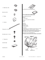
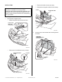
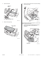
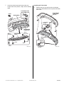
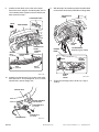
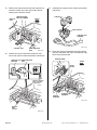
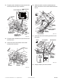
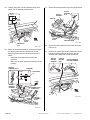
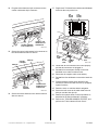
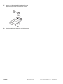
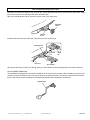
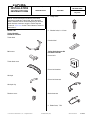
INSTALLATION
INSTRUCTIONS
Accessory
Application
TRAILER HITCH
2014 MDX
BII 48846-50039
Issue Date
July 2013
NOTE: These instructions include the procedures
required to install this Trailer Hitch. Once the trailer
hitch is installed, Acura recommends that you test the
trailer harness connector using the Trailer Harness
Tester Kit. Click here for the Trailer Harness Tester Kit
instructions.”
PARTS LIST
Publications No.
6
Flange bolts
2
Washer bolts, 6 x 14 mm
Trailer Hitch Kit
P/N 08L92-TZ5-200
Trailer hitch
Caution label
Ball mount
Trailer Hitch Harness Kit
P/N 08L91-TZ5-201
Control unit
Trailer hitch cover
Control unit bracket
Hitch pin
Control unit harness
Hitch pin clip
Receiver cover
Socket harness
2
© 2013 American Honda Motor Co., Inc. – All Rights Reserved.
Blade fuses, 7.5A
BII 48846-50039 (1305)
08L92-TZ5-2000-90
1 of 13
2
Blade fuses, 20A
Accessory User’s Information Manual
Block fuse, 20A
TOOLS AND SUPPLIES REQUIRED
2
Relays
10 mm Open end wrench
Ratchet
Torque wrench
10 mm, 17 mm, and 19 mm Sockets
Pushpin
5
Wire ties
Ruler
Scissors
Utility knife
Diagonal cutters
Isopropyl alcohol
Shop towel
Flange bolt, 6 x 16 mm
The following tool is available through the Honda Tool and
Equipment Program. On the iN, click on: Service >
Service Bay > Tool and Equipment Program, then enter
the number under “Search”. Or, call 888-424-6857.
Plastic Trim Tool (T/N SILTRIMTL10)
Shoulder bolt, 6 x 19 mm
Illustration of the Trailer Hitch Installed on the Vehicle
CONTROL
UNIT
2
CONTROL UNIT
HARNESS
2 RELAYS
Flange nuts
Urethane tape
Subharness kit
QBN0701AH
SOCKET
HARNESS
2 of 13
BII 48846-50039 (1305)
TRAILER HITCH
© 2013 American Honda Motor Co., Inc. – All Rights Reserved.
INSTALLATION
Client Information: The information in this installation
instruction is intended for use only by skilled
technicians who have the proper tools, equipment, and
training to correctly and safely add equipment to your
vehicle. These procedures should not be attempted by
“do-it-yourselfers.”
•
Remove the intake air tube (two clips).
•
Disconnect the negative cable from the battery.
2 CLIPS
INTAKE AIR TUBE
Removing the Vehicle Parts
1.
Disconnect the negative cable:
•
Wrap a shop towel around the hood latch.
HOOD LATCH
(Wrap with
a shop towel.)
QBN1504BK
2.
Pull each lever, and fold down the left and right third
row seats.
LEFT/RIGHT
THIRD ROW SEATS
(Fold down.)
QBN1201BK
•
Remove the front bulkhead cover (10 clips).
FRONT BULKHEAD
COVER
10 CLIPS
2 LEVERS
(Pull.)
QB01910AH
QBN1202BK
© 2013 American Honda Motor Co., Inc. – All Rights Reserved.
BII 48846-50039 (1305)
3 of 13
3.
Open the cargo lid.
5.
CARGO LID
(Open.)
Remove the rear junction box cover (seven retaining
tabs and two hooks).
FRONT
2 HOOKS
REAR JUNCTION
BOX COVER
HANDLE LOCK
7 RETAINING
TABS
QBN0702AH
4.
Remove the cargo lining.
QBN0703AH
If the vehicle is equipped with a spare tire, continue with
step 6; otherwise go to step 7.
6.
CARGO LINING
Locate and remove the rubber plug to access the
spare tire hoist shaft. Lower the spare tire
completely.
RUBBER
PLUG
SPARE TIRE
HOIST SHAFT
QB01913AH
SPARE TIRE
QBN0704AH
4 of 13
BII 48846-50039 (1305)
© 2013 American Honda Motor Co., Inc. – All Rights Reserved.
7.
Under the vehicle locate and remove the rear
bumper lower face (4 bolts, 2 clips, and 10 retaining
tabs).
Installing the Trailer Hitch
8.
10 RETAINING TABS
Remove the four clip nuts from the rear bumper
lower face, and transfer the four clip nuts to the trailer
hitch cover.
REAR BUMPER
LOWER FACE
(Discard.)
FRONT
REAR BUMPER
2 CLIP NUTS
(reused)
REAR BUMPER
LOWER FACE
BOLT
(Discard.)
BOLT
(Discard.)
REAR BUMPER
(inside)
TRAILER HITCH
COVER
BOLT
CLIP
CLIP
BOLT
QBN0705AH
© 2013 American Honda Motor Co., Inc. – All Rights Reserved.
BII 48846-50039 (1305)
2 CLIP NUTS
(reused)
QBN0706AH
5 of 13
9.
Install the trailer hitch cover to the rear bumper.
Secure the cover using the 10 retaining tabs, two 6 x
14 mm washer bolts included in the kit and the two
bolts removed in step 7.
11. With the help of an assistant, position the trailer hitch
on the vehicle and loosely install the six flange bolts.
TRAILER HITCH
COVER
10 RETAINING TABS
FRONT
REAR BUMPER
TRAILER
HITCH
TRAILER HITCH
COVER
WASHER
BOLT,
6 x 14 mm
REAR BUMPER
(inside)
6 FLANGE BOLTS
95 N·m (9.7 kgf·m, 70 lbf·ft)
BUMPER
BEAM
WASHER
BOLT,
6 x 14 mm
FRONT
BOLT
(reused)
SOCKET
HARNESS
BOLT
(reused)
TRAILER
HITCH
COVER
QBN0707BH
10. Install the socket harness 7-pin socket to the trailer
hitch with one 6 x 16 mm flange bolt, one 6 x 19 mm
shoulder bolt, and two flange nuts.
QBN0709BH
12. Torque the six flange bolts to 95 N·m (9.7 kgf·m,
70 lbf·ft).
TRAILER HITCH
SOCKET HARNESS
7-PIN SOCKET
SHOULDER BOLT,
6 x 19 mm
2 FLANGE NUTS
FLANGE BOLT,
6 x 16 mm
QBN0708CH
6 of 13
BII 48846-50039 (1305)
© 2013 American Honda Motor Co., Inc. – All Rights Reserved.
13. Secure the trailer hitch cover to the bumper beam
with two clips removed in step 7.
Installing the Control Unit and Socket Harnesses
16. Install the control unit bracket to the control unit.
CONTROL UNIT
FRONT
CONTROL UNIT
BRACKET
BUMPER
BEAM
REAR
BUMPER
QBN0711AH
17. Using isopropyl alcohol on a shop towel, thoroughly
clean the control unit bracket where the urethane
tape will attach.
CLIP
(reused)
TRAILER
HITCH
COVER
CLIP
(reused)
QBD2626AH
14. Using isopropyl alcohol on a shop towel, thoroughly
clean the trailer hitch cover where the caution label
will attach.
30 mm
(1.2 in.)
CONTROL
UNIT
BRACKET
(Clean with
isopropyl
alcohol.)
FRONT
URETHANE
TAPE
(Cut.)
URETHANE
TAPE
QBN0712AH
18. Using scissors, cut one urethane tape to the
measurement shown. Wrap the cut urethane tape to
the control unit bracket as shown.
CAUTION
LABEL
TRAILER HITCH COVER
(Clean with isopropyl alcohol.)
QBN0710AH
15. Attach the caution label to the trailer hitch cover at
the area shown.
© 2013 American Honda Motor Co., Inc. – All Rights Reserved.
BII 48846-50039 (1305)
7 of 13
19. Remove the vehicle bolt from the rear junction box.
Insert the control unit to the rear junction box lid
opening at the direction shown.
VEHICLE
BOLT
21. Install the two relays into the control unit harness
relay block.
2 RELAYS
REAR JUNCTION
BOX LID OPENING
FRONT
RELAY BLOCK
CONTROL UNIT
HARNESS
CONTROL UNIT
REAR JUNCTION
BOX
QBN0713AH
20. Position the control unit bracket as shown, and
secure the control unit bracket with the vehicle bolt.
QBN0715AH
22. Route the control unit harness along the vehicle
harness, and attach the control unit harness relay
block to the vehicle panel.
VEHICLE PANEL
CONTROL UNIT REAR JUNCTION
BRACKET
BOX
FRONT
RELAY
BLOCK
CLIP
Rest the urethane
tape on the rear
junction box.
VEHICLE
HARNESS
CONTROL UNIT
HARNESS
QBN0716AH
VEHICLE
BOLT
(reused)
QBN0714AH
8 of 13
BII 48846-50039 (1305)
© 2013 American Honda Motor Co., Inc. – All Rights Reserved.
23. Plug the control unit harness 14-pin connector into
the rear junction box 14-pin connector.
14-PIN CONNECTOR
26. Under the vehicle, route the socket harness as
shown, and secure it to the vehicle bracket with one
wire tie.
REAR JUNCTION
BOX
FRONT
CONTROL
UNIT
VEHICLE
BRACKET
WIRE TIE
SOCKET HARNESS
7-PIN SOCKET
CONTROL UNIT
HARNESS 12-PIN
CONNECTOR
CONTROL UNIT
HARNESS 14-PIN
CONNECTOR
SOCKET
HARNESS
REAR
JUNCTION
BOX
QBN0717AH
24. Plug the control unit harness 12-pin connector into
the control unit.
QBN0719AH
TRAILER HITCH
27. Locate and remove the vehicle grommet from the
floor panel.
FRONT
FLOOR PANEL
TRAILER HITCH
25. Secure the control unit harness to the vehicle
harness with one wire tie.
INSULATION
INSULATION
VEHICLE
GROMMET
(Discard.)
PUSHPIN
CONTROL
UNIT
HARNESS
WIRE
TIE
PUSHPIN
VEHICLE
HARNESS
QBN0720AH
28. Using a pushpin, pierce the insulation.
QBN0718AH
© 2013 American Honda Motor Co., Inc. – All Rights Reserved.
BII 48846-50039 (1305)
9 of 13
29. Using a utility knife, cut the insulation at the area
shown. Do not damage the floor panel.
31. Secure the socket harness clip to the vehicle frame.
30 mm
(1.2 in.)
SOCKET
HARNESS
SOCKET
HARNESS
CLIP
WIRE TIE
30 mm
(1.2 in.)
PUSHPIN
HOLE
TRAILER
HITCH
FRONT
UTILITY
KNIFE
QBN0723BH
INSULATION
(Cut.)
QBN0721AH
30. Route the socket harness 8-pin connector through
the vehicle grommet hole, and seat the socket
harness grommet into the vehicle grommet hole.
NOTE:
•
•
32. Secure the socket harness to the trailer hitch with
one wire tie.
33. Remove the vehicle ground bolt. Attach the socket
harness ground terminal to the vehicle ground
terminal, and reinstall the vehicle ground bolt.
Install the socket harness by holding the
grommet.
Make sure to check that the grommet is secured
properly.
VEHICLE
GROMMET HOLE
VEHICLE FRAME
VEHICLE
GROUND
TERMINAL
VEHICLE
GROUND
BOLT
SOCKET HARNESS
GROUND TERMINAL
GROMMET
inside
FLOOR PANEL
VEHICLE
GROUND
BOLT
(reused)
outside
FRONT
SOCKET
HARNESS
GROMMET
SOCKET
HARNESS 8-PIN
CONNECTOR
FRONT
VEHICLE
GROMMET
HOLE
QBN0724AH
QBN0722AH
10 of 13
BII 48846-50039 (1305)
© 2013 American Honda Motor Co., Inc. – All Rights Reserved.
34. Plug the socket harness 8-pin connector into the
control unit harness 8-pin connector.
37. Plug the two 7.5A blade fuses and the two 20A blade
fuses into the rear junction box.
20A
BLADE
FUSES
7.5A
BLADE
FUSES
REAR
JUNCTION
BOX
SOCKET HARNESS
8-PIN CONNECTOR
CONTROL UNIT
HARNESS 8-PIN
CONNECTOR
QBN0725AH
35. Secure the control unit harness 8-pin connector to
the vehicle harness with one wire tie.
20A
BLADE
FUSE
SOCKET
HARNESS
WIRE TIE
WIRE TIE
20A
BLADE
FUSE
2 BLADE
FUSES,
7.5A
REAR
JUNCTION
BOX
QBN0727BH
38. Check that all wire harnesses are routed properly
and that all connectors are plugged in.
39. Reinstall all removed parts except for the front
bulkhead cover and the intake air tube.
40. Reconnect the negative cable to the battery.
41. Reinstall the front bulkhead cover and the intake air
tube.
VEHICLE
HARNESS
CONTROL UNIT
HARNESS 8-PIN
CONNECTOR
QBN0726AH
36. Secure the socket harness to the vehicle harness
with one wire tie.
42. Press and hold the radio power button for two
seconds to restore the radio and navi (if equipped)
system functions.
43. Reset the clock on vehicles without navigation.
44. Secure the ball mount to the trailer hitch with one
hitch pin and the hitch pin clip.
45. Restore the systems back to normal operation as
described in the Service Manual if necessary.
46. Refer to the “TRAILER HARNESS TESTER”, and
perform the “Trailer Harness Circuit Check.”
© 2013 American Honda Motor Co., Inc. – All Rights Reserved.
BII 48846-50039 (1305)
11 of 13
47. Remove and discard the 20A blade fuse from the
subharness kit. Put the 20A block fuse into the
subharness kit.
20A
BLOCK
FUSE
SUBHARNESS
KIT
48. Place the subharness kit into the vehicle glove box.
12 of 13
BII 48846-50039 (1305)
© 2013 American Honda Motor Co., Inc. – All Rights Reserved.
Give a copy of this page to your client
Whenever you remove the hitch pin clip, the hitch pin, and the ball mount, store them securely in the cargo area. Install
the receiver cover into the opening at the end of the trailer hitch.
When you reinstall the ball mount, store the receiver cover in the cargo area.
RECEIVER
COVER
TRAILER
HITCH
Install the ball mount into the trailer hitch using a hitch pin clip and hitch pin.
TRAILER HITCH
HITCH PIN
CLIP
HITCH PIN
HITCH
PIN
BALL MOUNT
After the first 600 miles (1,000 km) of towing, have your Acura Dealer re-check the tightness of the trailer hitch bolts.
How to Handle Subharness
This subharness is designed for use with the installation of an electric brake controller. When installing an electric brake
controller, place the 20A block fuse in the rear junction box as specified by the Trailer Hitch User’s Information Manual.
Refer to the vehicle’s Owner’s Manual for the detailed information about handling this subharness.
SUBHARNESS
© 2013 American Honda Motor Co., Inc. – All Rights Reserved.
BII 48846-50039 (1305)
13 of 13