1
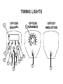
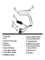
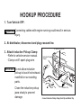
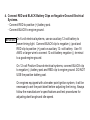
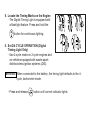
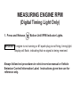
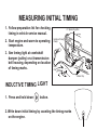
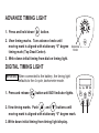
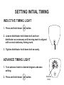
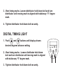
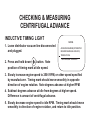
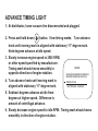
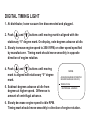
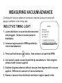
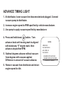
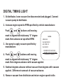
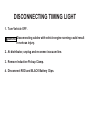
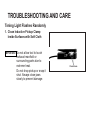
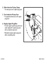
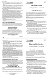
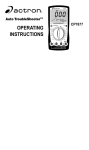
TIMING LIGHT INSTRUCTIONS CP7527 INDUCTIVE CP7528 ADVANCE CP7529 DIGITAL Actron, is a Business Unit of SPX Corporation. SAFETY PRECAUTIONS For safety reasons, read this manual thoroughly before operating Timing Light. Always refer to and follow safety messages and test procedures provided by manufacturer of vehicle or equipment being tested. The safety messages presented below and throughout this manual are reminders to operator to exercise extreme care when using this test instrument. ! WARNING Indicates a potentially hazardous situation which, if not avoided, could result in serious injury or death. IMPORTANT Indicates a situation which, if not avoided, may result in damage to the test equipment or vehicle. SAFETY EQUIPMENT Fire Extinguisher For gasoline/chemical / electrical fires Safety Goggles Protect eyes from Battery Acid / Gasoline / Flying Debris Protective Gloves Protect Hands from Battery Acid / Hot Exhaust / Engine Parts / Flying Debris SAFETY INSTRUCTIONS Ventilation Operate vehicle in ventilated area. Moving Parts Remove Jewelry Do Not Wear Loose Clothing Tie Up Long Hair Keep Hands Away From Moving Parts Set Brake Place Car In: Park (For Automatic) Neutral (For Manual) Set Parking Brake Disable Automatic Parking Brake Release Smoking and Open Flames Never smoke while working on car Keep sparks, and open flames away from vehicle Do not use fuel injector cleaning solvents when performing diagnostic tests Hot Surfaces Avoid Contact With: Exhaust Manifolds Pipes Radiator Mufflers (catalytic converters) Battery Do Not Lay Tools on Battery Do Not Touch Battery Acid Do Not Create Short Between Terminals If using an auxiliary battery: Connect Jumper Wire Between Negative Terminal on Auxiliary Battery and Ground on Vehicle Place Battery at least 18 inches Above Floor High Voltage 30,000 to 50,000 Volts Present At: Ignition Coil Distributor Cap Ignition Wires Spark Plugs Use Insulated Pliers Do Not Use Timing Light if Cords are Damaged TIMING LIGHTS CP7529 DIGITAL 6 2/4 Cycle 15 CP7528 ADVANCE CP7527 INDUCTIVE RPM Adv 7 11 8 14 14 12 9 13 10 16 16 2 1 3 4 5 1. Timing Light 2. Lens 3. Inductive Pickup Clamp 4. RED Clip 5. BLACK Clip 6. 4-digit LED Display 7. 2 Cycle Mode Indicator 8. 4 Cycle Mode Indicator 9. RPM Mode Indicator 10. Advance Mode Indicator 11. 2/4 Cycle Mode Button 12. Flashlight Button 13. RPM/Adv Mode Button 14. Increase and Decrease Advance Buttons 15. Advance Knob 16. ON Button HOOKUP PROCEDURE 1. Turn Vehicle OFF. ! WARNING Connecting cables with engine running could result in serious injury. 2. At distributor, disconnect and plug vacuum line. 3. Attach Inductive Pickup Clamp · Refer to vehicle service manual. · Clamp on #1 spark plug wire. # 1 Spark Plug Wire Inductive Pickup Clamp IMPORTANT Do not allow inductive pickup to touch hot exhaust manifold or surrounding parts. Close the inductive pickup jaws slowly to prevent damage. Red Clip POS. Black Clip Connect Inductive Pickup Clamp, Red Clip and Black Clip 4. Connect RED and BLACK Battery Clips on Negative Ground Electrical Systems. · Connect RED to positive (+) battery post. · Connect BLACK to engine ground. IMPORTANT On 6-volt electrical systems, use an auxiliary 12-volt battery to power timing light. Connect BLACK clip to negative (-) post and RED clip to positive (+) post on auxiliary 12- volt battery. Use 18 AWG or larger wire to connect 12-volt battery negative (-) terminal to a good engine ground. On 12-volt Positive Ground electrical systems, connect BLACK clip to negative (-) battery post and RED clip to engine ground. DO NOT USE the positive battery post. On engines equipped with a breaker point ignition system, it will be necessary to set the point dwell before adjusting the timing. Always follow the manufacturers specifications and test procedures for adjusting dwell angle and idle speed. 10 DC 0 3 6 10 A TDC OP 1-6 16N 1-6 UDC button for continuous lighting. 6. Set 2/4 CYCLE OPERATION (Digital Timing Light Only) · Use 2-cycle mode on 2-cycle engines and on vehicles equipped with waste-spark distributorless ignition systems (DIS). O 10 5. Locate the Timing Marks on the Engine · The Digital Timing Light is equipped with a flashlight feature. Press and hold the IMPORTANT When connected to the battery, the timing light defaults to the 4- cycle, tachometer mode. · Press and release button until correct indicator lights. MEASURING ENGINE RPM (Digital Timing Light Only) 1. Press and Release Button Until RPM Indicator Lights. IMPORTANT If engine is not running or #1 spark plug is not firing, timing light display will flash, indicating that no signal is being received. Always follow test procedures in vehicle service manual or Vehicle Emission Control Information Label. Instructions given here are for reference only. MEASURING INITIAL TIMING 1. Follow preparation list for checking timing in vehicle service manual. 2. Start engine and warm to operating temperature. 3. Aim timing light at crankshaft damper (pulley) or at transmission bell housing, depending on location of timing marks. # 1 Spark Plug Wire Inductive Pickup Clamp Red Clip POS. Black Clip INDUCTIVE TIMING LIGHT 1. Press and hold down button. 2. Write down initial timing by counting the timing marks on the engine. ADVANCE TIMING LIGHT 1. Press and hold down button. 2. View timing marks. Turn advance knob until moving mark is aligned with stationary 0 degree timing mark (Top Dead Center). Advance Knob 3. Write down initial timing from dial on timing light. DIGITAL TIMING LIGHT IMPORTANT When connected to the battery, the timing light defaults to the 4-cycle, tachometer mode. 1. Press and release button until ADV indicator lights. 2. View timing marks. Push and buttons until moving mark is aligned with stationary 0 degree mark. 3. Write down initial timing from timing light display. 2/4 Cycle RPM Adv SETTING INITIAL TIMING INDUCTIVE TIMING LIGHT 1. Press and hold down button. 2. Loosen distributor hold down bolt and turn distributor as necessary until moving mark is aligned with correct stationary timing mark. 3. Tighten distributor hold down bolt securely. ADVANCE TIMING LIGHT 1. Turn advance knob to desired degrees advance setting. 2. Press and hold down button. Advance Knob 3. View timing marks. Loosen distributor hold down bolt and turn distributor until moving mark is aligned with stationary 0 degree mark. 4. Tighten distributor hold down bolt securely. DIGITAL TIMING LIGHT 1. Push and buttons until display shows desired degrees advance setting. 2. View timing marks. Loosen distributor hold down bolt and turn distributor until moving mark is aligned with stationary 0 degree mark. 3. Tighten distributor hold down bolt securely. 2/4 Cycle RPM Adv CHECKING & MEASURING CENTRIFUGAL ADVANCE INDUCTIVE TIMING LIGHT 1. Leave distributor vacuum line disconnected and plugged. NOTES ADVANCE READING (RPM NOTED IN SERVICE MANUAL OR VECI) TIMING AT IDLE 2. Press and hold down button. Note CENTRIFUGAL ADVANCE position of timing mark at idle speed. 3. Slowly increase engine speed to 2500 RPM, or other speed specified by manufacturer. Timing mark should move smoothly in opposite direction of engine rotation. Note degrees advance at higher RPM. 4. Subtract degrees advance at idle from degrees at higher speed. Difference is amount of centrifugal advance. 5. Slowly decrease engine speed to idle RPM. Timing mark should move smoothly in direction of engine rotation, and return to idle position. ADVANCE TIMING LIGHT 1. At distributor, leave vacuum line disconnected and plugged. 2. Press and hold down button. View timing marks. Turn advance knob until moving mark is aligned with stationary 0 degree mark. Note degrees advance at idle speed. 3. Slowly increase engine speed to 2500 RPM, or other speed specified by manufacturer. Timing mark should move smoothly in opposite direction of engine rotation. 4. Turn advance knob until moving mark is aligned with stationary 0 degree mark. NOTES ADVANCE READING (RPM NOTED IN SERVICE MANUAL OR VECI) TIMING AT IDLE CENTRIFUGAL ADVANCE 5. Subtract degrees advance at idle from degrees at higher speed. Difference is amount of centrifugal advance. 6. Slowly decrease engine speed to idle RPM. Timing mark should move smoothly in direction of engine rotation. DIGITAL TIMING LIGHT 1. At distributor, leave vacuum line disconnected and plugged. 2. Push and buttons until moving mark is aligned with the stationary 0 degree mark. On display, note degrees advance at idle. 3. Slowly increase engine speed to 2500 RPM, or other speed specified by manufacturer. Timing mark should move smoothly in opposite direction of engine rotation. 4. Push and buttons until moving mark is aligned with stationary 0 degree mark. 5. Subtract degrees advance at idle from degrees at higher speed. Difference is amount of centrifugal advance. NOTES ADVANCE READING (RPM NOTED IN SERVICE MANUAL OR VECI) TIMING AT IDLE CENTRIFUGAL ADVANCE 6. Slowly decrease engine speed to idle RPM. Timing mark should move smoothly in direction of engine rotation. MEASURING VACUUM ADVANCE Checking the vacuum advance mechanism requires a vacuum pump with gauge in addition to the timing light. INDUCTIVE TIMING LIGHT 1. Leave distributor vacuum line disconnected and plugged. Connect vacuum pump to distributor. 2. Increase engine speed to RPM specified by vehicle manufacturer. 3. Press and hold down NOTES RPM XXXX VACUUM XXXXX ADV. RPM XX VACUUM XX ADVANCE WITH VACUUM - ADVANCE WITHOUT VACUUM Contribution of Vacuum button. Note advance at specified RPM. 4. Use pump to apply vacuum specified by manufacturer. Note degrees advance with vacuum applied. 5. Subtract degrees advance without vacuum from degrees with vacuum applied. Difference is amount of vacuum advance. 6. Remove vacuum from distributor and return engine speed to idle. ADVANCE TIMING LIGHT 1. At distributor, leave vacuum line disconnected and plugged. Connect vacuum pump to distributor. 2. Increase engine speed to RPM specified by vehicle manufacturer. 3. Use pump to apply vacuum specified by manufacturer. 4. Press and hold down button. Turn advance knob until moving mark is aligned with stationary 0 degree mark. Note advance at specified RPM. 5. Subtract degrees advance without vacuum from degrees with vacuum applied. Difference is amount of vacuum advance. 6. Remove vacuum from distributor and return engine speed to idle. NOTES RPM XXXX VACUUM XXXXX ADV. RPM XX VACUUM XX ADVANCE WITH VACUUM - ADVANCE WITHOUT VACUUM Contribution of Vacuum DIGITAL TIMING LIGHT 1. At distributor, leave vacuum line disconnected and plugged. Connect vacuum pump to distributor. 2. Increase engine speed to RPM specified by vehicle manufacturer. Push and buttons until moving mark is aligned with stationary 0 degree mark. Note advance at specified RPM. 3. Use pump to apply vacuum specified by manufacturer. 4. Push and buttons until moving NOTES RPM XXXX VACUUM XXXXX ADV. RPM XX VACUUM XX ADVANCE WITH VACUUM - ADVANCE WITHOUT VACUUM Contribution of Vacuum mark is aligned with stationary 0 degree mark. Note degrees advance with vacuum applied. 5. Subtract degrees advance without vacuum from degrees with vacuum applied. Difference is amount of vacuum advance. 6. Remove vacuum from distributor and return engine speed to idle. DISCONNECTING TIMING LIGHT 1. Turn Vehicle OFF. ! WARNING Disconnecting cables with vehicle engine running could result in serious injury. 2. At distributor, unplug and reconnect vacuum line. 3. Remove Inductive Pickup Clamp. 4. Disconnect RED and BLACK Battery Clips. TROUBLESHOOTING AND CARE Timing Light Flashes Randomly 1. Clean Inductive Pickup Clamp Inside Surfaces with Soft Cloth IMPORTANT Do not allow tool to touch exhaust manifold or surrounding parts due to extreme heat. Do not drop pickup or snap it shut. Always close jaws slowly to prevent damage. Clean Areas 2. Slide Inductive Pickup Clamp To new spot on #1 spark plug wire 3. Turn Inductive Pickup Over To opposite direction on #1 spark plug wire 4. Replace Spark Plug Wire If solid copper spark plug wires are used replace #1 spark plug wire with a resistive type wire. Reinstall original spark plug wire after completing test. ACTRON HAND TOOLS