1
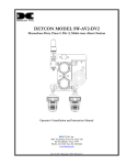
INSTRUCTIONS
FOR DRAIN PUMP KIT - DCE D Series
ASSEMBLY INSTRUCTIONS
Using the kit parts shown in the figure below, mount the pump assembly (P/N 12-2503-21, sold
separately) to the bracket and assemble fittings, hoses, and electrical connector. Two white
pre-formed hoses are included in the kit: Use the hose with a straight end for old-style bins having a
“tee” fitting at the sump/bin drain, or use the hose with a formed elbow for current models having the
sump drain routed inside the bin.
Note: Before installing the discharge elbow onto the pump nipple, visually inspect elbow for
proper assembly of check valve and spring (see detail A below.) Tighten the elbow so no more
than two threads show and the elbow is pointing towards the REAR (motor end) of the assembly.
Electrical
Connector
Discharge Elbow
Long Tie-Wrap
White Pre-Formed
Hose, Chose 1 of 2
Discharge
Elbow
Check
Valve
Ratchet Clamp
Short Tie-Wrap
Switch Sensing Tube
BLACK - L01
Spring
Detail A
WHITE - L02
RED - BIN LEVEL CONTROL
17-3363-01
GRAVITY DRAIN CONVERSION INSTRUCTIONS
Use these instructions to convert an existing gravity drain system to a pump drain system.
Unit must be completely accessible from the rear to complete the installation of discharge tubing. If
necessary, remove the unit from it’s built in location to provide full access.
1. Set ON/OFF/BIN LEVEL control knob to the OFF position. Disconnect power and water to the unit.
Remove electrical control box cover and kick plate. Remove existing bin drain tubing (BE
PREPARED FOR WATER TO DRAIN FROM BOTH THE STORAGE BIN AND DRAIN TUBING.)
2. Uncoil the 10-foot long discharge tubing and push one end completely onto the barbed discharge
elbow of the pump and securely fasten it with the worm-gear clamp (See figure 1). Route the other
end through the rear of the unit to a convenient drain location.
3. Carefully slide the pump assembly into the base of the unit and fasten it to the base using two
black snap fasteners, pushing them through the holes in the bracket and the matching holes in the
base of the unit. Push white pre-formed tube onto bin drain fitting and secure with one short tie-wrap.
(See figure 1)
Bin Drain Fitting
Figure 1
Short Tie-wrap
Worm Gear
Clamp
Discharge Hose
Snap Fasteners
2
4. Unplug connector from power cord and connect pump harness to power cord and machine
connector (located near compressor),
5. Restore power to the unit and with the ON/OFF/BIN LEVEL control still in the OFF position, pour
several quarts of water into the bin. The drain pump should turn on and pump the water out of the
bin, perhaps cycling on and off several times during the process. Pump cycling is normal since the
pump-out rate of the drain pump is greater than the rate of drain through the bin.
6. While the pump is discharging water, THOROUGHLY CHECK THE ENTIRE DRAIN SYSTEM FOR
LEAKS.
7. Re-install unit into built-in or free-standing location. ENSURE THAT NO KINKS OCCUR IN
WATER INLET OR DRAIN TUBING.
8. Restore potable water supply and manually advance the unit’s timer to the HARVEST position.
Turn the ON/OFF/BIN LEVEL control knob ON to the required operating range setting for the
application. Check unit for at least one cycle to ensure proper operation and to allow a final check for
leaks of any kind.
9. Re-install control box cover and kick-plate. Conversion of a gravity drain system to a drain pump
system is now complete.
COMM
NC
R
NO
BK
IF DRAIN PUMP
IS INSTALLED
IF DRAIN PUMP
IS INSTALLED
POWER IN
EARTH GROUND
DRAIN PUMP
PRESSURE
SWITCH
GN/Y
W
3
GN/Y
W
2
COMM
W
BIN
LEVEL
CONTROL
BIN LEVEL
CONTROL
COMPRESSOR
BU
CUBE SIZE
CONTROL
(INITIATE
TIMER
SWITCH)
BK/W
FAN
MOTOR
HOT GAS
SOLENOID
C
NC
R
W
W
Y
W
W
R
Y
DRAIN
PUMP
BU
NC
NO
PUMP
PRESSURE
SWITCH
ON
SAFETY
PRESSURE
SWITCH
OFF
1
CUBE SIZE
CONTROL
PUMP
MOTOR
BK
N
L1
BK
BK
SAFETY
PRESSURE
SWITCH
NO
BN
W
TIMER
WATER
R/W
SOLENOID
6
1
2
C
BK
NC
HARVEST TIME
ADJUSTABLE
FROM 120 TO 300 SEC.
FACTORY SET TO 170
FAN
MOTOR
6
NO
1
TIMER
2
WATER
PUMP
WATER
SOLENOID
W
DRAIN
PUMP
MOTOR
RELAY - CURRENT
HOT GAS
SOLENOID
1
S
SWITCHES ON THIS UNIT
SHOWN IN TIMED PORTION
OF THE FREEZE CYCLE
WITH DRAIN PUMP IN OPERATION
M
1
3
OVERLOAD
COMPRESSOR
INSTALLATION INSTRUCTIONS
1. UNIT MUST BE INSTALLED AND IN
ACCORDANCE WITH LOCAL CODES.
2. CONNECT A POTABLE WATER LINE TO 1/4 NPT ON WATER
VALVE LOCATED IN THE FRONT ON THE MACHINE.
3. ROUTE 3/8" ID FLEXIBLE HOSE FROM LEFT FRONT OF M
PER INSTRUCTIONS FOR DCE33PA IN SERVICE MANUAL.
4. CONNECT THE ELECTRICAL POWER CORD TO
A PROPERLY WIRED AND GROUNDED RECEPTICAL.
3
ACHINE
5. BY TURNING THE ON/OFF SWITCH/BIN LEVEL
CONTROL DIAL IN A CLOCKWISE DIRECTION
TO APPROXIMATE OPERATING RANGE MARKING.
UNIT IS NOW IN AUTOMATIC OPERATION.
17-3353-01