1
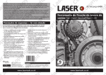
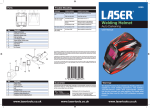
ig
yr
t
SE
R
A
R
py
C
ri
o
L
h
py
yr
A
t
SE
C
ig
ri
o
py
gh
LA
ht
R
p
ri
yr
t
SE
C
gh
i
op
gh
LA
R
t
yr
t
SE
C
i
op
gh
LA
ht
R
LA
yr
t
SE
C
S
ig
op
LA
R
LA
ht
y
SE
C
ri
SE
o
gh
LA
R
py
LA
R
t
SE
C
r
SE
C
ig
op
R
LA
ht
R
yr
C
SE
C
ig
op
R
op
L
h
R
y
A
t
C
r
yr
SE
C
i
op
gh
op
LA
R
yr
t
yr
SE
C
ig
ig
op
py
LA
ht
R
ht
ri
y
S
C
ri
gh
ER
op
gh
L
A
t
yr
t
SE
C
gh
i
op
gh
LA
R
LA
t
yr
t
SE
C
ig
op
LA
R
LA
ht
y
SE
C
ri
SE
o
gh
LA
R
py
LA
R
t
SE
C
r
SE
ig
op
R
LA
ht
R
yr
C
SE
C
E
ig
o
C
op
Part No. 5741
Engine Timing Tool Kit
Mazda | Ford
www.lasertools.co.uk
www.lasertools.co.uk
py
C
ri
o
L
h
py
yr
A
t
SE
C
ig
ri
o
py
gh
LA
ht
R
p
ri
yr
t
SE
C
gh
i
op
gh
LA
R
t
yr
t
SE
C
i
op
gh
LA
ht
R
LA
yr
t
SE
C
S
ig
op
LA
R
LA
ht
y
SE
C
ri
SE
o
gh
LA
R
py
LA
R
t
SE
C
r
SE
C
ig
op
R
LA
ht
R
yr
C
SE
C
ig
op
R
op
L
h
R
y
A
t
C
r
yr
SE
C
i
op
gh
op
LA
R
yr
t
yr
SE
C
ig
ig
op
py
LA
ht
R
ht
ri
y
S
C
ri
gh
ER
op
gh
L
A
t
yr
t
SE
C
gh
i
op
gh
LA
R
LA
t
yr
t
SE
C
ig
op
LA
R
LA
ht
y
SE
C
ri
SE
o
gh
LA
R
py
LA
R
t
SE
C
r
SE
ig
op
R
LA
ht
R
yr
C
SE
C
E
ig
o
Plan Layout
R
C
A
B
A
SE
R
D
Ref
A
C586
t
B
C034
Description
999 7151/303 376/49JE01
054/303 367/49UN30 3376/21
162/21 162b
49N010 101/MOT 1430/303
620/999 7201/21-163
999 7152/49JEO1 061/303
507/21-210
Camshaft Locking Plate
Locking Strap
Crankshaft Timing Pin
Timing Pin
C
op
yr
ig
C
C036
D
C035
OEM Ref
49 UN30 310610/303-1061
2
www.lasertools.co.uk
www.lasertools.co.uk
7
py
C
ri
o
L
h
py
yr
A
t
SE
C
ig
ri
o
py
gh
LA
ht
R
p
ri
yr
t
SE
C
gh
i
op
gh
LA
R
t
yr
t
SE
C
i
op
gh
LA
ht
R
LA
yr
t
SE
C
S
ig
op
LA
R
LA
ht
y
SE
C
ri
SE
o
gh
LA
R
py
LA
R
t
SE
C
r
SE
C
ig
op
R
LA
ht
R
yr
C
SE
C
ig
op
R
op
L
h
R
y
A
t
C
r
yr
SE
C
i
op
gh
op
LA
R
yr
t
yr
SE
C
ig
ig
op
py
LA
ht
R
ht
ri
y
S
C
ri
gh
ER
op
gh
L
A
t
yr
t
SE
C
gh
i
op
gh
LA
R
LA
t
yr
t
SE
C
ig
op
LA
R
LA
ht
y
SE
C
ri
SE
o
gh
LA
R
py
LA
R
t
SE
C
r
SE
ig
op
R
LA
ht
R
yr
C
SE
C
E
ig
o
Applications
Incorrect or out of phase engine timing can result in damage to the valves.
The Tool Connection cannot be held responsible for any damage caused by
using these tools in anyway.
The application list for this product has been compiled cross referencing the OEM Tool Code
with the Component Code.
Safety Precautions – Please read
If the engine has been identified as an interference engine valve to piston damage will
occur if the engine is run with a broken Cam belt.
•
Disconnect the battery earth leads
(check radio code is available)
•
Mark the direction of the chain
before removing
•
Remove spark or glow plugs to make
the engine turn easier
•
•
Do not use cleaning fluids on belts,
sprockets or rollers
It is always recommended to turn the
engine slowly, by hand and to
re-check the camshaft and crankshaft
timing positions.
SE
R
R
Safety Precautions
Always make a note of the route of
the auxiliary drive belt before
removal
•
Turn the engine in the normal
direction (clockwise unless stated
otherwise)
A
•
t
•
•
Do not use the timing chain to lock
the engine when slackening or
tightening crankshaft pulley bolts
Do not turn the crankshaft or
camshaft when the timing belt/chain
has been removed
Crankshafts and Camshafts may only
be turned with the chain drive
mechanism fully installed.
•
Do not turn crankshaft via camshaft
or other gears
A compression check of all cylinders should be performed before removing the cylinder
head.
Always consult a suitable work shop manual before attempting to change the Cam belt or
Chain.
The use of these engine timing tools is purely down to the user’s discretion and Eldon Tool
and Engineering Ltd cannot be held responsible for any damage caused what so ever.
ALWAYS USE A REPUTABLE WORKSHOP MANUAL
• Full applications list on website
Manufacturer
Model
CC
Note
Fuel
Engine
Year
Ford
Mondeo
1.8
SCi
P
CFBA
2003 - 2007
Mazda
3
2.3
MPS
P
L3 Turbo
2006 - 2009
3
2.3
MPS
P
L3 Turbo
2006 - 2009
3
2.0
DISI i-stop
P
LF (MZR DISI)
2009 - 2013
• Always refer to the vehicle manufacturer’s service manual or a suitable proprietary instruction book
3
2.3
MPS
P
L3 Turbo
2009 - 2013
5
2.0
DISI
P
MZR 2.0 (LF)
2010 - 2013
• Incorrect or out of phase engine
timing can result in damage to the valves
6
2.3
MPS
P
L3 Turbo
2005 - 2007
6
2.0
DISI
P
LF (MZR DISI)
2010 - 2013
CX-7
2.3
P
L3 Turbo
2007 - 2012
CX-7
2.3
P
L3 Turbo
2007 - 2012
• Check the diesel injection pump
timing after replacing the chain
• Observe all tightening torques
C
op
yr
ig
•
Do not turn the camshaft, crankshaft
or diesel injection pump once the
timing chain has been removed
(unless specifically stated)
•
In most cases the tools are specific to this type of engine and are necessary for Cam belt or
chain maintenance.
6
www.lasertools.co.uk
www.lasertools.co.uk
3
py
C
ri
o
L
h
py
yr
A
t
SE
C
ig
ri
o
py
gh
LA
ht
R
p
ri
yr
t
SE
C
gh
i
op
gh
LA
R
t
yr
t
SE
C
i
op
gh
LA
ht
R
LA
yr
t
SE
C
S
ig
op
LA
R
LA
ht
y
SE
C
ri
SE
o
gh
LA
R
py
LA
R
t
SE
C
r
SE
C
ig
op
R
LA
ht
R
yr
C
SE
C
ig
op
R
op
L
h
R
y
A
t
C
r
yr
SE
C
i
op
gh
op
LA
R
yr
t
yr
SE
C
ig
ig
op
py
LA
ht
R
ht
ri
y
S
C
ri
gh
ER
op
gh
L
A
t
yr
t
SE
C
gh
i
op
gh
LA
R
LA
t
yr
t
SE
C
ig
op
LA
R
LA
ht
y
SE
C
ri
SE
o
gh
LA
R
py
LA
R
t
SE
C
r
SE
ig
op
R
LA
ht
R
yr
C
SE
C
E
ig
o
Instructions
Instructions
Developed to lock the cam and crankshaft in position and allow the removal and
replacement of the timing chain fitted to the twin Cam engines list below.
N.B The information given below is for reference only. The Tool Connection
recommends the use of Manufacturer data or Autodata.
R
Preparation and precautions:
•Removal of the timing chain will require the removal of the sump.
•Ensure the engine is at TDC cylinder number 1.
•Ensure the chain tensioner is fully retracted and held in the retracted position using a
suitable pin.
•Remove the crankshaft pulley using an appropriate pulley holding tool
•Always replace the crankshaft pulley friction washers with new washers.
SE
R
A: Camshaft Locking Plate
Fig. 1
A
Component A is used to lock both the
camshafts in their timed position as shown
in Fig. 1. Remove the cam cover and fit
Component A as shown below (engine at
TDC with Component B fitted)
1. Camshaft Setting / Locking Plate is used
to accurately align a datum slot, located
in the end of the camshafts. The various
slots cut into the edge of the plate
permit clearance around adjacent parts.
2. Follow the service manual instructions to
remove the camshaft cover and timing
belt cover.
3. Turn engine in the normal direction of
rotation until the camshaft setting/
locking plate can be inserted into the
machined slot in the end of the camshaft.
5. Turn the engine in the normal direction
of rotation until the timing mark on the
injection pump sprocket lines up with the
cast lug on the timing cover.
6. Remove the plug from the cylinder block
access hole and screw in the TDC location
pin.
t
7. Slowly turn the crankshaft clockwise until
the web makes contact with the end of
the pin. Number 1 cylinder is now set at
TDC on ignition stroke.
4
B
Fig. 2
Component B is used to lock crankshaft in
its timed position(TDC number 1 cylinder).
Locate and remove the blanking plug from
the engine block. Rotate the crankshaft in
a clockwise direction and stop just before
TDC number 1 cylinder. Fit the Component
B in place of the blanking plug. Continue
turning the crankshaft in a clockwise
direction until it stops against component
B See Fig. 2.
C
op
yr
ig
B: Crankshaft Locking Tool
C|D
4. Crankshaft TDC Location Pin is designed
to screw into the cylinder block and
provide a stop for the crankshaft to be
positioned against to set the TDC
position.
5