1
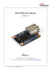
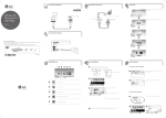
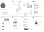
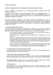
LG Synchro Unit Commissioning Procedure
How to Use this guide
This guide book has been designed to set out a procedure for commissioning LG’s Synchro
split units. It is designed to be very simple to follow and assumes the engineer has never
commissioned one of these systems before.
At the end of this guide there is a commissioning sheet included, this should be completed
and returned. A copy of this information will be useful when processing any warranty claims
for the equipment.
Some Definitions
Synchro Systems have a single condenser piped to 2, 3 or 4 indoor units. These are used
to give better air distribution than a single fan coil, It is essential that all the fan coils serve
the same area as they all operate as one. The end user only controls the master fan coil, the
slaves are controlled automatically.
The Fan Coil capacity must match the Condenser capacity, the only permitted combinations
are those listed in the Sales Booklet or Service Manual.
When a Synchro System is used addressing of the Outdoor Unit is required prior to it
being powered up, and a set procedure followed (see Pages 4 - 6 for instructions).
Ignoring these instructions will result in the system failing to operate correctly.
This Addressing procedure must be carried out as part of the Commissioning procedure on
new systems, or whenever an Indoor or Outdoor PCB is replaced.
LGEUK AC Department June 2007
Synchro Commissioning
1
Pressure Testing
Ensure that all service valves are shut tight prior to pressure test, this will avoid nitrogen
leaking past the valves into the condensing unit.
All Air-Conditioning systems must be pressure tested before refrigerant is released into the
pipe work. Pressure testing must be carried out using Oxygen free dry Nitrogen only and
MUST be carried out on all the service ports. If you unit has two service valve connect two
pipes if it only has one port only one gauge line can be used.
Pressure testing tends to be carried out in stages; generally it is considered good practice to
test the pipes prior to connection to the condensing unit to avoid leaking into the condenser
past the service valves. The pipe work should be pressure tested for 24 hours in three
stages:
Stage 1
Stage 2
Stage 3
3.0 Bar for minimum 3 minutes
15.0 Bar for minimum 3 Minutes
38.0 Bar for minimum 24 hours
Make a note of the temperature at the time of the pressure test as the pressure will fall by 2
psig for every 1°C drop in ambient temperature and rise by 2 psig for every 1°C temperature
rise.
Evacuation
The system will now need evacuating. Evacuation MUST be carried out on all the service
valves. If you unit has two service valve connect two pipes if it only has one port only one
gauge line can be used.
The time of evacuation is purely a function of your vac pump and the ambient temperature.
With reference to the chart below check the Torr required at the ambient temperature, once
you reach this level continue to vac the system for a further 15 minutes. If the system holds
the vac at the level achieved there is no water vapour present in the pipe work. However, if
the pressure raises it means water vapour is boiling-off in the tubes. You must repeat the
vacuuming process for a further 15 minutes, until no further rise is experienced.
40
Temperature C
35
30
25
20
15
10
5
0
5
7
9
11
13
16
Pressure Torr
Steam table of water
LGEUK AC Department June 2007
Synchro Commissioning
2
20
25
30
Additional Refrigerant Charge
Once a suitable vacuum has been achieved, additional charge may need to be added.
If the interconnecting pipe work is longer than the stated length additional refrigerant charge
will need to be added. You must establish how much additional refrigerant charge is
required, this must be done accurately and the charge weighed in with refrigerant scales.
Make a note of the charge added as this will be useful later in the unit’s life.
R410A Synchro Units Additional Refrigerant Charge
UU48 (Non-Inverter)
Units are pre-charged for 30M of main pipework + 20M Total of branch pipe-work.
Main pipework, add 70 grams per meter over 30M.
Branch pipework, add 30 grams per meter over 20M.
UU48W + UU60W (Inverter)
Units are pre-charged for 30M of main pipework + 20M Total of branch pipe-work.
Main pipework, add 50 grams per meter over 30M.
Branch pipework, add 30 grams per meter over 20M.
UU72 (Non-Inverter)
Units are pre-charged for 5M of main pipework + 20M Total of branch pipe-work.
Main pipework, add 50 grams per meter over 5M.
Branch pipework, add 30 grams per meter over 20M.
UU100 (Non-Inverter)
Units are pre-charged for 5M of main pipework + 20M Total of branch pipe-work.
Main pipework, add 50 grams per meter over 5M.
Branch pipework, add 30 grams per meter over 20M, + additional 20 grams per meter for all
3/8” Liquid Line branch pipework (size 48 indoor units).
LGEUK AC Department June 2007
Synchro Commissioning
3
Before Powering up the System.
To avoid complications the following will assist commissioning.
Disconnect all centralised controllers, service computers, additional PC boards and field
supplied condensate pumps this will make life simpler for you. These can be added, and
tested, once the system operation is proved to be correct.
Group Control
Group control is not possible on Synchro Systems, the Remote Controller must only be wired
to a single Indoor Unit and the Group Switch on the rear of the remote controller must be set
to single (SG).
LGEUK AC Department June 2007
Synchro Commissioning
4
When a system is to be set up as a Synchro System addressing is required.
Addressing
The addressing sequence should be carried out as part of the commissioning procedure or
when replacing indoor or outdoor unit PCB. Addressing is carried out at the outdoor PCB.
Set up the PCB as shown below with the power to the system switched off.
Switch on the power wait 10 seconds then press the ADDR / TEST button (small black
button under large capacitors) for 10 seconds, the green LED will flicker, release
button, leave system to auto address for 10 minutes. Power off system for 3 minutes,
power back on now the system is ready to run.
UU48W, UU60W
These units are addressed using a set of 3 plugs marked ADDR1, ADDR2, ADDR3.
Settings are as follows:One Indoor Unit Leave All 3 Plugs in
Two Indoor Units Remove Plug ADDR1
Three Indoor Units Remove Plugs ADDR1
ADDR2
Four Indoor Units Remove All ADDR
Plugs
LGEUK AC Department June 2007
Synchro Commissioning
5
UU48, UU72, UU100
These units are addressed using a set of dip switches marked Zone SW1, individually
marked 1, 2, 3, 4.
Settings are as follows:One Indoor Unit, Switch 1 Up
in the On Position.
Two Indoor Units, Switches 1 + 2 Up in
the On Position.
Three Indoor Units, Switches 1, 2 + 3
Up in the On Position.
Four Indoor Units, Switches 1, 2, 3 + 4
Up in the On Position.
LGEUK AC Department June 2007
Synchro Commissioning
6
Testing the Unit
Once you have completed the pressure tests, evacuation, additional gas charge and Address
settings, you can commission the system and record its performance.
Turn the fan coil / coils in cooling mode set the
temperature to 18°C or test mode and check the air off
temperatures of every fan coil.
Test Mode: Using a hard-wired controller.
Press the house button and the hour down button for 3
seconds, LO will appear.
During Test mode the unit will run for 18 minutes
without using the ambient air Thermistor, all safety
functions will still operate.
To exit test mode press ON OFF button once or wait 18
minutes and the fan coil will return to normal operation.
Test Mode: with Infra red controller.
Press the forced operation button on the front of the fan coil for 5 seconds, the unit will beep
it will now start in test mode, on units with an LED display LO will be displayed.
During Test mode the unit will run for 18 minutes without using the ambient air Thermistor, all
safety functions will still operate.
To exit test mode press ON OFF button once or wait 18 minutes and the fan coil will return to
normal operation.
LGEUK AC Department June 2007
Synchro Commissioning
7
Recording Commissioning data:
Cooling mode:
When all the units are running the performance of the system should be checked.
Do not take any measurements for the first 5 minutes of operation.
Condensing Unit
At the power input terminals measure:
Voltage before compressor starts
Voltage when compressors are running, check volt drop is less than 5%.
Current drawn by condensing unit (compare with the nameplate current)
At the suction service valve measure pressure (should be to approximately 125 psig).
At the discharge service port measure pressure (should be to approximately 340 psig).
Fan Coils
Measure air off and air on temperatures, in a room with an ambient temperature of 21°C an
air off temperature of 10°C or better should be achieved.
If air off and air on temperatures are the same you better check your pipe work isn’t crossed.
Once satisfactory readings have been taken the unit should be tested in heating mode.
Heating mode:
When all the units are running the performance of the system should be checked.
Do not take any measurements for the first 10 minutes of operation.
Condensing Unit
Measure current drawn by condensing unit (compare with the nameplate current)
At the service valves measure discharge pressure it should be at least 360 psig
Fan Coils
Measure air off and air on temperatures, in a room with an ambient temperature of 21°C an
air off temperature of 35°C or better should be achieved.
LGEUK AC Department June 2007
Synchro Commissioning
8
Some Additional Settings
On the back of the remote controller there are additional switches:
Top Switch for Sensor (Room Temperature Setting)
Position Remo, the unit will use only the sensor in the remote controller (not recommended
as it is not very sensitive)
Position Indoor (factory set) the unit will only use the return air sensor in the Indoor Unit for
temperature control
Position 2TH Remo + Indoor the unit will use both the Indoor Unit return air and the remote
controller sensors.
LGEUK AC Department June 2007
Synchro Commissioning
9
Middle Switch for Ceiling Height Default ESP
When ceiling cassettes are being installed in areas with high or low ceilings the fan speeds
can be adjusted to suit.
In Position V-L or 1 the fan speed is reduced for ceiling heights below 2.7 m
In position FH or 2 (factory set) the fan will run at normal speed this is the setting for ceilings
of 2.5 - 2.9 m
In position V-H or 3 the fan speed is increased for ceiling heights of 3m +
Switch for Group control
When more than 1 Fan Coil is mounted in a single room, each with it’s own Outdoor unit and
is to be controlled from a single remote controller, this is called group control. A switch
setting on the back of the Remote Controller must be made to accommodate this.
Factory setting is single or SG (this setting must be used on Synchro Systems).
When group control is used set to Group or GR1 (this is not available on Synchro Systems).
When centralised controls are used set to the third position GR2.
LGEUK AC Department June 2007
Synchro Commissioning
10