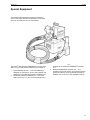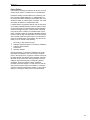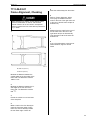
1
Service Manual
Trucks
Group
710–500
Frame Rails and Crossmembers
VN/VHD
PV776-TSP143123
Foreword
The descriptions and service procedures contained in this manual are based on designs and methods studies carried out up to August 2000.
The products are under continuous development. Vehicles and components produced
after the above date may therefore have different specifications and repair methods.
When this is believed to have a significant bearing on this manual, supplementary service bulletins will be issued to cover the changes.
The new edition of this manual will update the changes.
In service procedures where the title incorporates an operation number, this is a reference to an S.R.T. (Standard Repair Time).
Service procedures which do not include an operation number in the title are for general information and no reference is made to an S.R.T.
The following levels of observations, cautions and warnings are used in this Service
Documentation:
Note: Indicates a procedure, practice, or condition that must be followed in order to
have the vehicle or component function in the manner intended.
Caution: Indicates an unsafe practice where damage to the product could occur.
Warning: Indicates an unsafe practice where personal injury or severe damage to the
product could occur.
Danger: Indicates an unsafe practice where serious personal injury or death could occur.
Volvo Trucks North America, Inc.
Greensboro, NC USA
Order number: PV776-TSP143123
© 2000 Volvo Trucks North America, Inc., Greensboro, NC USA
All rights reserved. No part of this publication may be reproduced, stored in
retrieval system, or transmitted in any forms by any means, electronic, mechanical, photocopying, recording or otherwise, without the prior written
permission of Volvo Trucks North America, Inc..
Contents
General .................................................................................................... 3
Frame Rails and Crossmembers ........................................................... 3
Specifications ......................................................................................... 5
Frame Rails ........................................................................................... 5
Tools ........................................................................................................ 9
Standard Tools and Equipment ............................................................. 9
Special Tools ....................................................................................... 10
Special Equipment ............................................................................... 11
Design and Function ........................................................................... 13
Frame Rails and Crossmembers ......................................................... 13
Troubleshooting ................................................................................... 35
HUCK-FIT® Fastener Troubleshooting ................................................ 35
Service Procedures .............................................................................
Frame Rail, Replacement ....................................................................
Frame Alignment, Checking ................................................................
Frame Alignment, Adjustment .............................................................
Intermediate Crossmember, Replacement (Rivets Under the Flame
Flange) .................................................................................................
Intermediate Crossmember, Replacement (Bolted and Exposed
Rivets) ..................................................................................................
Closing Crossmember, Replacement ..................................................
Engine Crossmember, Replacement ...................................................
Rear Suspension Crossmember (Bogie), Replacement .....................
Frame Length, Adjustment ..................................................................
Body Bound Bolt, Installation ..............................................................
HUCK-FIT® Fastener, Removal ...........................................................
HUCK-FIT® Fastener, Installation ........................................................
37
37
43
44
45
46
47
47
49
51
56
56
57
Feedback
Operation Numbers
1
2
Group 71
General
General
Frame Rails and Crossmembers
The information in this manual covers specifications, tools, designs, function and service procedures for VN/VHD Frame Rails and Crossmembers. This information is
essential for maintenance and proper serviceability of the Frame Rails and Crossmembers.
3
4
Group 71
Specifications
Specifications
Frame Rails
Material ............................................................................................... 758.4 MPa (110,000 psi) yield heat treated steel
Distance between rails
Front ............................................................................................................................................ 1080 ± 2 mm (outside)
Rear ............................................................................................................................................................ 836
+2.7
−4.6
Frame rail end taper ..................................................................................................................................................
mm
27
Available Frame Heights and Thicknesses
Frame height
Frame thickness
266 mm (VN) .................................................................................................................................... 6 mm, 7 mm, 8 mm
300 mm (VN) .............................................................................................................................................. 7 mm, 8 mm
300 mm (VHD)
........................................................................................................................... 7 mm, 8 mm, 11.1 mm
5
Group 71
Specifications
Bolt Hole Patterns
Hole spacing with Volvo T-Ride suspension .................................... 60 mm (2.26 in.) (vert) x 50 mm (1.97 in.) (horiz)
(applicable only from 1685 mm (65.2 in.) from front edge of the rail and rearward)
Note: Hole size for this spacing must be 15.5 mm (0.61
in.) long.
W7001187
A 60 mm (2.36 in.)
B 60 mm (2.36 in.)
C 60 mm (2.36 in.)
D 60 mm (2.36 in.)
E 60 mm (2.36 in.)
F 50 mm (1.97 in.)
G 43 mm (1.69 in.)
H 60 mm (2.36 in.)
I 60 mm (2.36 in.)
J 60 mm (2.36 in.)
K 43 mm (1.69 in.)
L 50 mm (1.97 in.)
6
Group 71
Specifications
Hole Spacing With All Suspensions Except Volvo T-Ride
Front axle crossmember and forward ............................................................... 60 mm (2.26 in.) (vert) x 50 mm (horiz)
Rear of front axle crossmember ............................................................ 76.3 mm (3 in.) (vert) x 50.8mm (2 in.) (horiz)
Note: Hole size for this spacing must be 17 mm (0.66
in.) long.
W7001188
A 74.1 mm (2.92 in.)
B 50.8 mm (2.00 in.)
C 50.8 mm (2.00 in.)
D 50.8 mm (2.00 in.)
E 74.1 mm (2.92 in.)
F 76.0 mm (3.00 in.)
G 56.8 mm (2.24 in.)
H 50.8 mm (2.00 in.)
I 50.8 mm (2.00 in.)
J 50.8 mm (2.00 in.)
K 56.8 mm (2.24 in.)
L 76.0 mm (3.00 in.)
7
Group 71
Specifications
Tightening Torques, Frame Rail Bolts
(for property class 10.9 bolts and property class 10 nuts)
Bolt Size
Torque
M6 ...........................................................................................................................
12 ± 2 Nm (9 ± 1.5 ft-lb)
M7 ...........................................................................................................................
22 ± 3 Nm (16 ± 3 ft-lb)
M8 ...........................................................................................................................
30 ± 5 Nm (22 ± 4 ft-lb)
M10 .........................................................................................................................
60 ± 10 Nm (44 ± 7 ft-lb)
M12 (bolts crossmembers together) ......................................................................
105 ± 20 Nm (78 ± 13 ft-lb)
M14 (bolts crossmembers to frame) ......................................................................
200 ± 33 Nm (148 ± 24 ft-lb)
M16 (bolts crossmembers to frame) ......................................................................
275 ± 45 Nm (204 ± 34 ft-lb)
M18 .........................................................................................................................
360 ± 55 Nm (267 ± 44 ft-lb)
M20 (bolts cab mounts to frame) ...........................................................................
540 ± 90 Nm (400 ± 67 ft-lb)
M22 .........................................................................................................................
730 ± 120 Nm (541 ± 90 ft-lb)
M24 .........................................................................................................................
900 ± 140 Nm (667 ± 111 ft-lb)
Proper frame bolt thread engagement ........................................................ Max. 13 mm past nut, min. two (2) threads
8
Group 71
Tools
Tools
Standard Tools and Equipment
All listed tools and equipment are not required for each service procedure. Review the
service procedure to be performed to determine which tools and equipment will be required.
Torque wrench
Tape measure
C-clamps
Drift pins
Hammer
Metal saw
Gas cutting torch
Metal grinder
Welding machine
Reamer (0.652 inch)
9
Group 71
Tools
Special Tools
The J-38460-A is a digital protractor, available from
Kent-Moore (telephone: 800–328–6657.)
W7000708
The J-44771 Frame Rail Guide Support is available from
Kent Moore (telephone: 800–328–6657.)
W7001140
10
Group 71
Tools
Special Equipment
The following special equipment may be required for
work on the frame rails and crossmembers. This equipment can be ordered from your manufacturer.
W0000397
The HUCK® Manufacturing 940INTRKTV tool kit is available from your local HUCK® distributor and consists of:
1
2
Nose assembly 99-1481 – This nose assembly is
designed for use with the 16 mm (5/8”) fastener and
attaches to the model 585 hydraulic installation tool.
Model 585 hydraulic installation tool – This handheld tool has a 3.5 m (12 ft.) hose assembly that is
3
attached to the model 940 POWERIG® hydraulic
unit.
Model 940 POWERIG® hydraulic unit – This
portable 110V electric power unit provides hydraulic
fluid under pressure to the model 585 hydraulic installation tool. (This tool is also available in 220V.)
11
Group 71
Tools
The Digital Angle Gauge. The Anglemaster is a digital
inclinometer, available from Dana-Spicer (telephone:
419–535–4300.)
Drill with Magnetic base.
W0001876
Plumb Bob.
W0001877
Threaded rods, 1/2 in. diameter, 1200 mm (48 in.) long
(2 required) with 12 nut.
W0001878
12
Group 71
Design and Function
Design and Function
Frame Rails and Crossmembers
The frame for the VN/VHD series has frame sidemember
designs for vehicles produced by Volvo Trucks North
America. The designs include two sidemember heights,
three sidemember thicknesses, and a flared shape.
The frame height is constant for the entire length of the
rail. The rail height is either 266 mm, called the Low Profile frame, or 300 mm, called the High Profile frame. The
low profile frame may have a thickness of either 6 mm, 7
mm, 8 mm or 11.1 mm. The high profile height frame
may a have thickness of 7 mm, 8 mm or 11.1 mm
(VHD). The rails of the frame are separated at the front
edge a distance of 1080 mm (outside edges). From a
position just rearward of the front engine crossmember
to a position just forward of the rear engine crossmember the rails are tapered closer together. From that point
to the rear edge, the distance is 836 mm (inside edges).
Note: Frame dimensions are specified in millimeters due
to design. To obtain the approximate dimension in
inches, multiply mm by 0.03937.
Because the frame rails are made of a high strength
heat-treated steel, only the frame modifications detailed
in this information are permitted, in order to ensure that
the structural integrity of the rails is maintained.
In conjunction with the new frame design, the allowable
bolt hole patterns in the frame web are specified and
must be strictly followed.
W7001181
V 1080 mm (42.5 in.)
W 836 mm (32.9 in.)
X 266 mm (10.48 in.)
Y 300 mm (11.82 in.)
13
Group 71
Design and Function
W7001180
VN/VHD Frame rails with crossmembers:
1
2
3
4
5
Axle
Axle
VN
Axle
Axle
Forward with extension (VHD)
Back with extension (VHD)
Forward (VHD)
Back (VHD)
The frame consists of two steel side rails joined by several crossmembers. The frame for the VN/VHD series
models is made in a variety of configurations to allow
flexibility in adapting the frame for different transport requirements.
See the following design information:
•
•
•
•
•
14
“Side Members” page 15
“Crossmembers” page 17
“Mountings and Brackets” page 24
“Fasteners” page 25
“Frame Material Behavior” page 26
Group 71
Design and Function
Side Members
The side members, or frame rails, are constructed of 760
MPA (110,000 psi) yield heat treated steel. There are
several combinations of side member height and thicknesses. The smaller height, referred to as the Low Profile
frame, has a web height of 266 mm, and may be either 6
mm, 7 mm, 8 mm or 11.1 mm (VHD) thick. The larger
height, referred to as the High Profile frame, has a height
of 300 mm and may be either 7 mm or 8 mm thick.
W7001182
X 266 mm (10.48 in.)
Y 300 mm (11.82 in.)
These combinations of height and thickness provide for
the variety of load and usage characteristics necessary
to meet the hauling requirements of nearly any tractor.
The flange width is a constant 90 mm for all combinations of web height and thickness.
Unlike previous frame designs, the side members are
not an equal distance apart for their entire length. When
viewed from the side, the side members appear straight.
Viewed from above, the frame rails are flared outward
from a point just forward of the rear engine crossmember. This design provides for increased lateral, vertical,
and torsional stiffness. The result is improved vehicle
integrity, handling, accident avoidance, and collision energy absorption. Widening the frame at the front also
minimizes the need for cut outs in the frame flange to
adapt the side members to various vendor engines.
Regardless of the frame rail height, thickness, and
length, the basic frame design and dimensions are the
same. The front rail separation is 1080 mm, as measured from the outside of the frame rails, because the
front crossmember bolts to the outside of the rails. The
separation at the rear end is 836 mm, as measured from
the inside, because the closing crossmember is bolted
between the rails. The separation is a constant 836 mm
at a point 1635 mm from the front.
W7001183
X 1080 mm (42.5 in.)
Y 836 mm (32.9 in.)
15
Group 71
A standard hole pattern is designated for the frame rail
web. For vehicles with a complete Volvo T-Ride suspension, the hole pattern is 60 mm vertically between holes
and 50 mm horizontally. These dimensions apply to the
web behind the rear bend and forward of the rearmost
suspension component for the rear axles. For vehicles
with other than Volvo T-Ride suspension, the pattern is
60 mm vertically and 50 mm horizontally from behind the
forward spring hanger to the intermediate crossmember,
and 3 in. vertically by 2 in. horizontally from the front
axle crossmember to the rearmost suspension component for the rear axles. See “Bolt Hole Patterns” page 6.
The rear end of the frame is either cut straight or is tapered at a 27 degree angle. There are three different
closing crossmembers to accompany the style of frame
termination.
Design and Function
W7000378
Tapered frame end with tapered closing crossmember
W7000379
Straight frame end with splay closing crossmember
W7001005
VHD frame with closing crossmember
16
Group 71
Design and Function
Crossmembers
W7001043
VN Frame and Crossmember
1
Front Crossmember
2
Front Engine Crossmember
3
Rear Engine Crossmember
4
Transmission Crossmember
5
Intermediate Crossmember
6
Front-of-Axle Crossmember
7
Rear Suspension Crossmembers
8
Closing Crossmember
9
Rear Engine Support Brackets
10, 11
Front Spring Hanger
12, 13
Bumper Mounting Bracket
17
Group 71
Design and Function
W7001008
VHD Frame and Crossmember
1
Front Crossmember
2
Front Engine Crossmember
3
Rear Engine Crossmember
4
Transmission Crossmember
5
Intermediate Crossmember
6
Front-of-Axle Crossmember
7
Rear Suspension Crossmembers
8
Closing Crossmember
9
Rear Engine Support Brackets
10, 11
Front Spring Hanger
12, 13
Bumper Mounting Bracket
18
Group 71
Design and Function
The crossmembers provide a high degree of torsional
stiffness to the frame. They allow the vehicle to handle
the side forces caused by turns and uneven road conditions. Improved crossmember design and positioning for
the VN/VHD series models has resulted in reduced
weight, enhanced frame stability, improved truck handling, and reduced noise and vibration.
The crossmember components are to be treated as a
unit. Each consists of a beam and end plates. Where
beams and end plates are riveted together, they must
not be separated. If replacement is necessary, the replacement beams must be cut in the center and welded
together after the end plates have been mounted to the
frame rails. The front engine crossmember is an exception to this, in which case, the rivets are replaced by
body bound bolts.
Note: The numbers in the crossmember descriptions
that follow refer to the numbers on the frame and crossmember diagram at the beginning of the Crossmembers
subsection.
Front Crossmember
The front crossmember connects the front ends of the
side rails. It is 4 mm thick and has large holes to allow
maximum air flow to the radiator and charge air cooler. It
is physically bolted to the front crossmember and bumper
mounting brackets, which are bolted to the side rails.
W7000376
Fig. 1: VN
19
Group 71
Design and Function
Front Engine Crossmember
The second crossmember is the front engine crossmember. It is riveted to the front spring hangers, which are
bolted to the side members. It is designed to support the
forward end of the front suspension and the front engine
mount, which is a single point suspension at the center
of the crossmember. The crossmember is universal in
that it can accommodate engines made by Volvo or by
other manufacturers. This crossmember is simply rotated
180 from the Volvo engine position to adapt to other
vendor engines.
Unique brackets have been designed for fitting each
vendor engine to the VN/VHD series engine mounts. Because the second crossmember coincides with the
spring hangers, it provides support against side-bending
forces generated by driving in curves.
W0001879
Fig. 2: VHD
Rear Engine Crossmember
The next crossmember is the rear engine crossmember.
It is supported by the rear engine support brackets and
provides support against side loads that occur during vehicle turning. This crossmember is attached to the rear
engine mounting brackets. If the vehicle is equipped with
a Volvo transmission, the brackets are bolted to the engine flywheel housing. For vendor transmissions, the
brackets are bolted to the clutch housing.
Transmission Crossmember
The transmission crossmember is the first crossmember
rear of the transmission. The stiffness of this crossmember is improved over earlier models due to wider
end-plate attachment flanges. Its higher placement on
the frame provides greater structural strength. It is positioned so that there is sufficient prop-shaft clearance
without having to bend the crossmember.
The rivets that connect the beam to the end plates on
this crossmember are covered by the frame flange and
are not accessible.
20
Group 71
Design and Function
Intermediate Crossmember
The intermediate crossmember functions as the anchorage for the prop-shaft center bearing mounting in
addition to its normal function. Longer wheelbase vehicles may have one or two additional intermediate
crossmembers installed.
Note: Removal of the transmission and intermediate
crossmembers requires cutting the old crossmember in
half and unbolting the end plates from the frame. Installation requires cutting the new crossmember in half,
bolting the halves in place, and welding them together.
CAUTION
Possible material failure. The quality of the weld on a
replacement crossmember is important to the structural strength of the crossmember. All crossmember
welding must be performed by a certified welder to
guarantee the integrity of the crossmember. Failure to
properly perform the weld could result in failure of the
crossmember.
Front-of-Axle Crossmember
The front-of-axle crossmember exists mainly to provide
support for the suspension system. This particular crossmember is used on vehicles equipped with the Volvo
Optimized Air Suspension (VOAS) and the four–spring
leaf spring suspension. An aluminum front axle crossmember is available for reduced weight.
W7000374
21
Group 71
Design and Function
Rear Suspension Crossmember
There are a variety of rear suspension crossmembers
designed to accompany the axle suspension systems
they support. Because of the higher stresses and loading taken up at the rear suspension, this crossmember
has larger flanges than the other crossmembers.
The rear suspension crossmembers shown at right are
for 4x2 tractor with leaf springs or air ride (top), 6x4 tractor with leaf springs or Volvo Optimized Air Suspension
(middle), and 6x4 tractor with T-Ride (bottom).
W7000419
W0001880
22
Group 71
Design and Function
Closing Crossmember
The closing crossmember keeps the separation of the
frame rail ends fixed at 836 mm. The frame rail ends are
either tapered at a 27 degree angle, or are cut straight.
There is a crossmember designed for each of these
conditions.
W7000375
Fig. 3: Closing Crossmember
W7001010
Fig. 4: Closing Crossmember with tow hook
23
Group 71
Mountings and Brackets
The engine mounting system consists of brackets constructed of ductile iron castings and rubber cushion
isolators. With Volvo transmissions, the rear mount attaches to the engine flywheel housing. The rear mounts
attach to the clutch housing on all vendor transmissions.
Various brackets have been designed to adapt the Volvo
engine front isolators and cushions to vendor engines.
The rubber cushions on the engine mounts are tuned to
a precise vertical, longitudinal, and lateral stiffness. The
fine tuning of the mount cushions enhances truck performance by isolating engine vibrations and noise from the
chassis cab. These cushions have the ability to dampen
forces caused by frame distortion when driving off road
or on poor roads. The front and rear cushions are designed differently to allow a higher degree of movement.
The engine mounts minimize the motion of the engine.
In addition, they provide for easy service to the engine.
These advantages apply to all of the engines available
with the VN/VHD series models.
The fuel tank mountings are J-brackets that support and
attach the fuel tank(s) to the chassis. Dual fuel tanks are
stabilized by an additional crossover brace. They also
support the steps up to the cab.
24
Design and Function
Group 71
Design and Function
Fasteners
The crossmembers are connected to the frame rails using metric flange bolts. The beams and end plates of
individual crossmembers are either bolted to one another using metric flange bolts, or are riveted. Whenever
replacement of metric flange bolts is necessary, they
must be replaced with identical hardware. In cases
where rivets are used to connect beams and end plates,
they must not be disturbed because this will affect the
structural integrity of the crossmember.
Some crossmember beams are riveted to the end plates.
In cases where the rivets are accessible and must be removed, they should be replaced with a 16 mm body
bound bolt. These special bolts are manufactured with a
shank diameter that is slightly larger than the outer diameter of the thread so that the load is not placed on
the threaded portion of the bolts.
To make proper use of body bound bolts, the holes that
will be used must be reamed to a diameter of 0.79 mm
(0.031 in.) larger than the thread diameter. Proper joining of the crossmember and end plates or brackets is
accomplished when the shank of the body bound bolt is
in complete contact with the crossmember and inserts at
least 2/3 of the way into the hole in the component on
the nut side but does not extend out of the hole.
W7000383
1
2
3
4
5
Body bound bolt
Crossmember
Elastic stopnut
Hardened flat washer
End plate or spring bracket
Some components are fastened to the frame using
HUCK Spin® fasteners. If these fasteners must be replaced, metric flange bolts of the same size should be
used.
Huck fasteners can usually be removed by using an air
impact wrench.
®
For Description information see: “Huck-Fit Fasteners”
page 30.
W7000440
HUCK® Spin bolt and collar
For Troubleshooting and Diagnostics information see:
“HUCK-FIT® Fastener Troubleshooting” page 35.
For Service Procedure information see: “HUCK-FIT®
Fastener, Removal” page 56and “HUCK-FIT® Fastener,
Installation” page 57, “HUCK-FIT® Fastener, Installation”
page 57.
CAUTION
Possible component damage. Never mix HUCK® Spin
fasteners and flange fasteners within a hole pattern.
Mixing fastener types could cause the flange bolts to
come loose.
25
Group 71
Frame Material Behavior
Frame Strength
The amount of stress that a frame rail can withstand is a
function of several factors. The most important of these
are the Section Modulus and the Yield Strength. Section Modulus is a measure of the strength of a frame
member cross section. It is based on the height, thickness, and shape of the cross section, as well as the
width of the flange. It does not account for the material
used in that side rail. Yield Strength is a measure of the
strength of the material used, and is measured in MPa
(or psi). It is the maximum amount of force that can be
applied to the material to stretch or twist it and still have
it return to its original shape. These two factors are multiplied to produce the measure of strength known as
Resisting Bending Moment (RBM). Generally, when
the allowable level of RBM is exceeded, the frame will
likely experience failure. The degree of failure is related
to how much the RBM was exceeded and the method by
which it was exceeded.
The frame is designed to absorb the energy associated
with stresses produced by normal operation of the vehicle, including the higher stresses involved in off road
use. The frame is unlikely to experience failure as long
as the conditions assumed in design are not exceeded.
The failures usually occur in situations when either the
maximum allowable stress levels are exceeded or the
maximum levels have been reduced.
The cause of frame failures are placed into one of three
classifications:
1
2
3
26
Collisions
Excessive bending moment
Localized stress concentration
Design and Function
Group 71
Design and Function
Frame Failure
Frame failure resulting from collision can be in the form of
cracks, bends, twists, or broken rails or crossmembers.
Excessive bending moment failures are caused by overload, improper weight distribution, or misapplication of
the vehicle. Excessive bending moment failure will occur
at different areas on various types of vehicles. The result
will usually be twisted or cracked frame rails.
Localized stress concentration failures may be the result
of exceeding allowable bending moment, however, bending moment levels encountered during normal operation
would not be high enough to cause a failure. Incidental
to the failure is the condition of localized stress concentration. Possible causes for exceeding allowable bending
moment could be high bending loads concurrent with severe torsional loads as may be found in off road service.
Points of localized stress concentration may also be the
result of one or several of the following:
•
•
•
•
•
Poor body or fifth wheel mounting
Improper special equipment or accessory installation
Improper reinforcements
Loose bolts
Defective material
Special equipment or accessory installation can cause
high stress concentration due to the method of attachment or the weight of the equipment. Holes should never
be drilled through the flanges. Rapid changes of Section
Modulus, which could occur during operations such as
adding a large mounting plate for supporting special
equipment, should be avoided. Heavy equipment
mounted across the flanges or on the web of a side rail
may produce enough stress concentration to cause failure at the nearest crossmember, bracket, or other frame
stiffener, or through a nearby hole in the frame flange.
27
Group 71
Improper reinforcement or attachment of the reinforcement may cause more difficulty than the original
problem. Creation of localized stress concentrations may
reduce the frame’s load carrying capacity below its value
prior to adding reinforcements.
Frame failure may be complete failure (breakage) of the
frame or partial failure (frame misalignment). The list below describes several of the possible frame misalignment
conditions that could be caused by exceeding bending
moment.
Sag: Refers to a frame or side rail that is bent DOWN
from its proper position.
Bow: Refers to a frame of side rail that is bent UP from
its proper position.
Diamond: Refers to a condition in which one entire side
rail is moved forward or rearward of its correct alignment
in relation to the other side rail.
Twist: Refers to a condition where the entire frame has
been twisted. One rail appears to slope upward and the
other appears to slope down.
Sidesway: Refers to a side rail that is bent inward or
outward of its proper position from the other rail.
28
Design and Function
Group 71
Design and Function
Minimizing Frame Failure
The potential for frame failures can be reduced or eliminated by operating the vehicle within the design limits
and not creating areas of local stress concentration. Observance of the following guidelines will greatly minimize
the chances of frame failure.
Vehicles should only be used for the purposes for which
they were designed.
1
Avoid overloading vehicles.
2
Load vehicles evenly; avoid localized overloading.
3
Dump trucks should never be used to spread loads.
4
Tank trucks should have baffles.
5
Avoid excessive fifth wheel positions.
6
Avoid vehicle operation on extremely rough terrain.
Note: Only the following repairs/modifications are permitted on the VN/VHD series frame.
• Drilling holes for the attachment of equipment in accordance with the specified hole pattern.
• Cutting the frame to shorten it (never attempt to
lengthen the frame).
• Welding is only permitted on the riveted type crossmembers for replacement and on the frame rail
ends to shorten them.
Observe the following recommendations when altering a
frame rail.
1
Avoid abrupt changes in section modulus.
2
Never drill holes in frame rail flanges.
3
Ensure holes drilled in the frame rail web are
spaced according to the hole pattern specifications.
4
Use existing holes whenever possible.
5
Do not cut holes with a torch.
6
Do not cut notches in the rails.
7
Do not use rivets for attaching equipment through
holes in the frame. Always use a proper size Class
10.9 tighten flange bolts and Class 10 nut.
8
Welding should only be performed by a certified
welder.
29
Group 71
Design and Function
Huck-Fit® Fasteners
The HUCK-FIT® fastening system, which consists of the
fastener and installation tooling, was designed to meet
today’s high-strength industrial fastening needs.
The unique tension-tension method of the Lockbolt installation enables these fasteners to consistently retain
more than 95% of their initial clamp force, providing as
much as 10–20% higher clamp force and tensile strength
than conventional threaded fasteners. The swaged collar
design resists vibration, eliminating the back-off problem
encountered with threaded nuts and bolts.
The installation tooling allows easy operation and eliminates the need for specialized welding or tighten training.
Once the fastener is installed, visual inspection of the full
swage is sufficient to verify correct installation. This is in
sharp contrast to traditional threaded fasteners, for which
installation accuracy and inspection depend on the calibration of tighten equipment.
W7001149
The fasteners are removable, which makes them both exceptional and practical. The unique swaging action of the
lockbolt collar provides very high break-loose and backoff resistance. However, with enough applied force, the
collar can be removed without cutting. Standard impacttype tighten tooling can be used to remove the collar.
Fig. 5: Huck-Fit bolt
1
2
3
4
Pull Grooves
Pin Helix
Breakneck
Groove
Pintail
W7001150
Fig. 6: Head Markings
1
2
3
30
Grip Markings
Huck Symbol
Property class
Group 71
Design and Function
W7001151
Fig. 7: Hex Base Flange Collar
W7001152
Fig. 8: Collar Markings
1
2
Huck Symbol
Property class
31
Group 71
Design and Function
Identification
W7001147
Fig. 9: Typical Flange Bolt to Huck Bolt Crossover (Reference Grade 8 Flange)
32
1
S34X6227
8397081
9
MHCH-R16U
8075532 COLLAR
2
S343X6225
8397060
10 HUCK P/N
VTNA P/N
3
S343X622
839709
11 MHFF-DT16 -15
8075528
4
S343X6220
8397078
12 MHFF -DT16 -25
8075529
5
S343X6217
8397077
13 MHFF-DT16 -35
8075530
6
S343X6215
839706
14 MHFF-DT16 - 45
8075531
7
S343X6212
8397075
15 GRIP NO.
8
S344X6200
8397202 NUT
Group 71
Design and Function
Volvo vehicles currently use 16 mm (5/8”) fasteners. Fastener selection is based on the thickness of material to
be clamped. The fasteners have a ”grip” number. The
grip number is stamped into the head of each pin, and
represents the midpoint of the grip range (expressed in
millimeters) for that particular pin. The 16 mm pin is
available with a grip marking of 17. This pin has a grip
range of 10–24 mm. The 16 mm pin can also be identified by the raised nipple at the center of the pin head.
Grip No.
mm Range (minmax)
Decimal Range (minmax)
10
5 - 15
(0.19 - 0.59)
15
10 - 20
(0.39 - 0.78)
20
15 - 25
(0.59 - 0.98)
25
20 - 30
(0.78 - 1.18)
30
25 - 35
(0.98 - 1.37)
35
30 - 40
(1.18 - .1.57)
40
35 - 45
(1.37 - 1.77)
45
40 - 50
(1.57 - 1.96)
50
45 - 55
(1.77 - 2.16)
55
50 - 60
(2.96 - .2.56)
65
60 - 70
(2.36 - 2.75)
70
65 - 75
(2.55 - 2.95)
75
70 - 80
(2.75 - 3.15)
W7001148
Fig. 10: VTNA Flange bolt-to-bolt crossover
1
2
3
4
Pin-Tail
Pin-Tail
Break Area
Collar
Huck Bolt
33
34
Group 71
Troubleshooting
Troubleshooting
HUCK-FIT® Fastener Troubleshooting
Fault
Reason
Remedy
Inoperative POWERIG®
Check power source.
Loose or disconnected control cord
Check and tighten securely.
Loose or faulty hydraulic hose couplings
Check and tighten securely, or replace
faulty couplings.
Tool operates in reverse
Reversed hose connections between
POWERIG® and tool
Check and correct hose connections.
Tool leaks hydraulic oil
Depending on where leak occurs, defective
or worn O-rings, loose hydraulic hose connection at tool
Check and replace O-rings and backup rings, or tighten hydraulic hose.
Hydraulic oil overheats
POWERIG® not operating properly. Pump
motor rotation reversed
See POWERIG® instruction manual.
Restriction in hydraulic line
Check and tighten couplings, and replace if necessary.
Low or erratic hydraulic pressure supply
See POWERIG® instruction manual.
Defective or excessively worn piston O-ring
in tool
Replace O-ring and back-up rings.
Excessive wear or scoring of sliding surfaces of tool parts
Check and replace defective parts.
Operator not sliding nose completely onto
fastener pin-tail
Instruct operator in proper installation
methods.
Incorrect fastener length
Use correct length fastener.
Worn or damaged jaw segments
Check and replace jaw set.
Metal chips accumulated in pull grooves of
jaw segments
Clean jaw segments.
Excessive sheet gap
Eliminate excessive gap.
Improper tool operation
See fault ”Tool operates erratically and
fails to install fastener properly.”
Scored anvil in nose
Check and replace anvil.
Improper tool operation
See fault ”Tool operates erratically and
fails to install fastener properly.”
Tool fails to operate
Tool operates erratically and
fails to install fastener properly
Pull grooves on fastener pintail stripped during pull stroke
Collar of fastener not completely swaged
Tool ”hangs up” on swaged
collar
35
Group 71
Troubleshooting
Fault
Reason
Remedy
Pin-tail of fastener fails to
break.
Pull grooves on fastener stripped
See faults ”Tool operates erratically and
fails to install fastener properly” and
”Pull grooves on fastener pin-tail
stripped during pull stroke.”
Jaw segments do not maintain proper position in collet.
Improper operation of jaw follower
Check spring and install correct number
of follower O-rings. Clean before reassembling.
Hydraulic couplers leak oil.
Defective or worn O-ring in coupler body
Replace O-ring and back-up ring.
Pin-tail fails to eject from nose
assembly.
Bent or broken pin-tail ejector
Replace pin-tail ejector.
36
Group 71
Service Procedures
Service Procedures
7113-03-02-01
Frame Rail, Replacement
Before working on a vehicle, set the parking brakes,
place the transmission in neutral, and block the
wheels. Failure to do so can result in unexpected
vehicle movement and can cause serious personal injury or death.
Never work under or around a vehicle unless it is supported on jack stands of adequate rating. Failure to
use adequate jack stands can result in the vehicle
falling, which can cause serious injury or death to
anyone under the vehicle.
WARNING
Before beginning any service work on any part of the
air system, be certain that the air pressure has been
released. Failure to do so may cause a component to
violently separate, which can result in serious personal injury.
Removal
1
Park the vehicle on a level surface
with transmission in neutral and the
front wheels chocked. Raise the hood.
2
Remove the mounting screws from the
top and bottom of the bumper.
3
Remove the support rods from the left
and right sides of the bumper and remove the bumper.
WARNING
Fuel leaked or spilled onto hot surfaces or electrical
components can cause a fire. Clean up fuel spills immediately.
WARNING
Always wear appropriate eye protection to prevent the
risk of eye injury due to contact with debris or fluids.
WARNING
4
Disconnect the headlamp and foglamp
connectors and remove the hood
spring.
5
Remove the hood splash shields on
the left and right sides of the hood.
Disconnect the hood restraint cylinders.
6
Remove the fasteners to the hood
pivot and remove the hood.
Use a hoist or get assistance when lifting components
that weight 23 kg (50 lb) or more. Make sure all lifting
devices such as chains, hooks, or slings are in good
condition and are of the correct capacity. Make sure
hooks are positioned correctly. Always use a spreader
bar when necessary. The lifting hooks MUST NOT be
side loaded. Failure to follow these warnings may result in personal injury.
37
Group 71
Service Procedures
7
13
W7001186
1
2
W7001177
1
2
3
Hoist
Transmission Jack
Jack stand
Support the engine and transmission
jack with a hoist and transmission jack.
8
Remove the battery box cover and disconnect the batteries.
9
Remove the battery hold-down strap
and remove the batteries.
10
Remove the battery cable hold-down
bracket to the frame rail and disconnect the windshield wiper fluid pump.
11
Disconnect the supply and return lines
to the windshield washer reservoir.
Remove the clamp that secures the
drain valve pull cords to the air tanks.
12
Remove the air tank straps and the air
tanks.
Frame Rail Guide Support
Air Jack Stand
Remove the battery tray mounting
bolts. Remove the battery and air tank
support brackets.
Note: Some applications may require
supporting the rear cab suspension.
14
Using tool J–44771, support the frame
rail being removed with jack stands
and frame rail guide supports, which
are distributed equally throughout the
length of the frame rail.
Note: A minimum of three jack stands
and frame rail guide supports of adequate rating should be used for this
procedure.
15
Disconnect the fuel supply and return
line. Remove the fuel tank and fuel
tank J- brackets.
16
Remove the inner fender splash shield
and the lower bracket on the side of
the vehicle being worked on.
17
Remove the fasteners to the front
closing crossmember and the fasteners to the tow hook on the side of the
vehicle being worked on.
18
Remove the fasteners to the front
spring hanger and remove the bumper
support bracket.
Note: Support the front engine support crossmember.
38
J-44771
Group 71
Service Procedures
19
25
Remove the rear A/C line support
bracket, the bulkhead fitting and the
wheel speed sensor from the front
brake.
26
Disconnect the hood release cable and
remove the hood tube mount bracket.
27
Remove the ground wire and the
ground stud located on the frame rail
forward of the front cab support.
28
Remove any air valves, wiring and/or
air line brackets under the cab inside
and outside of the frame rail.
29
W7001185
1
Jack Stand
Support the radiator with a jack stand.
Remove the radiator support bracket
and the lower radiator isolator mount
on the side of the vehicle being
worked on.
20
Remove the pitman arm from the
steering gear.
W7001177
21
Stabilize the steering gear and remove
the fasteners that mount the steering
gear.
22
Remove the front axle bump stop from
the frame rail on the side of the vehicle being worked on.
1
2
3
Hoist
Transmission Jack
Jack Stand
Support the front of the cab with a
jack stand and remove the front cab
support.
30
Remove the lower spring pin on the
rear spring hanger to the front axle using tool 9996791.
23
Remove the Air Conditioning line support brackets inside the frame rail and
remove the upper shock absorber bolt.
31
Remove the rear spring hanger on the
front axle.
24
Remove the steering shaft carrier
bearing bracket and/or the power
steering reservoir bracket.
32
Remove the transmission mount
bracket and the transmission crossmember mounting bracket on the
frame rail being removed.
9996791
39
Group 71
33
Remove the fuel cooler and/or fuel water separator.
Service Procedures
41
34
Remove the air dryer and/or purge
tank.
35
Remove all the remaining clipping
brackets from the wiring or air-line harnesses located inside and outside of
the frame rail.
36
Remove any remaining air valves that
are mounted inside or outside the
frame rail.
37
Support the vertical exhaust pipe in
place, then remove the support
bracket for the exhaust.
38
Support the rear suspension crossmember with a jackstand, then remove
the upper shock brackets and the
bump stops from the rear suspension.
39
Remove all existing fasteners from the
rear suspension on the frame rail that
is being removed.
40
Remove all existing fasteners to the
crossmembers on the frame rail being
removed.
W7001179
1
2
Frame Rail Guide Support
Air Jack Stand
Slide and push the frame rail backward, while simultaneously moving the
jack stands, one after the other, to the
rear of the frame rail. This will adequately support the frame rail while it
is being removed.
Installation
Note: Do not tighten fasteners until they have been
properly installed. This will help maintain proper frame
alignment and will assist in obtaining proper height between the frame rails.
1
Slide and push the frame rail forward,
while simultaneously moving the jack
stands, one after the other, to the front
of the frame rail. This will adequately
support the frame rail while it is being
replaced.
2
Install all fasteners and crossmembers
on the frame rail being replaced.
3
Install fasteners from the rear suspension on the frame rail that is being
replaced.
4
Install the upper shock brackets and
the bump stops to the rear suspension.
5
Support the vertical exhaust pipe in
place, then install the support bracket
for the exhaust.
40
Group 71
Service Procedures
6
Install the air valves to the inside and
outside of the frame rail.
18
Install the rear A/C line support
bracket and remove the bulkhead fitting and wheel speed sensor from the
front brake.
7
Install all clipping brackets for the
wiring or air-line harnesses to the inside and outside of the frame rail.
8
Once this step is complete, go back
and tighten fasteners that have been
installed from steps 1 through 7 as follows: M14: tighten to a torque of 200 ±
33 Nm (148 ± 24 ft-lb), M16: 275 ± 45
Nm (204 ± 34 ft-lb).
19
Install the steering shaft carrier bearing bracket and/or the power steering
reservoir bracket.
200 ± 33 Nm
(148 ± 24 ft-lb)
275 ± 45 Nm
(204 ± 34 ft-lb)
21
Install the front axle bump stop to the
frame rail on the side of the vehicle
being worked on.
9
Install the fuel cooler and/or fuel water
separator.
10
Install the air dryer and/or purge tank.
22
Stabilize the steering gear and install
the fasteners that mount the steering
gear.
11
Install the transmission mount bracket
and the transmission crossmember
mounting bracket on the frame rail being replaced.
23
Install the pitman arm to the steering
gear.
12
Install the rear spring hanger on the
front axle.
13
Install the lower spring pin on the rear
spring hanger to the front axle using
9996791.
20
Install the A/C line support bracket
inside the frame rail and install the upper shock absorber bolt.
24
9996791
14
Install the front cab support.
15
Install any air valves, wiring and/or air
line brackets under the cab inside and
outside of the frame rail.
16
Install the ground wire and the ground
stud located on the frame rail forward
of the front cab support.
W7001185
17
Connect the hood release cable and
install the hood tube mount bracket.
1
Jack Stand
Install the radiator support bracket and
the lower radiator isolator mount.
41
Group 71
Service Procedures
25
Install the fasteners to the front spring
hanger and reinstall the bumper support bracket.
36
Reinstall the engine and transmission
jack. Reinstall the hoist and transmission jack.
26
Install the fasteners to the front closing
crossmember and the fasteners to the
tow hook on the side of the vehicle being worked on.
37
Check the frame alignment and make
sure everything is installed and properly tightened to specifications.
38
Install the fasteners to the hood pivot
blocks and install the hood.
27
Install the inner fender splash shield
and the lower splash shield support
bracket to the frame rail.
39
Install the hood splash shields on the
left and right sides of the hood. Connect the hood restraint cylinders.
28
Install the battery tray mounting fasteners and install the battery and air
tank support brackets.
29
Once this step is complete, go back
and tighten fasteners that have been
installed from steps 8 through 26, as
follows: M14: tighten to a torque of
200 ± 33 Nm (148 ± 24 ft-lb), M16:
275 ± 45 Nm (204 ± 34 ft-lb) and M20:
540 ± 90 Nm (400 ± 67 ft-lb).
30
Install the air tank straps and the air
tanks.
31
Reconnect the supply and return lines
to the wind shield washer reservoir.
Reinstall the clamp that secures the
drain valve pull cords to the air tanks.
32
Install the battery cable hold down
bracket to the frame rail and reconnect
the windshield wiper fluid pump.
33
Install the battery hold down strap and
remove the batteries.
34
Install the battery box cover and reconnect the batteries.
35
Reconnect the fuel supply and return
line. Install the fuel tank and the fuel
tank J- brackets.
42
200 ± 33 Nm
(148 ± 24 ft-lb)
275 ± 45 Nm
(204 ± 34 ft-lb)
540 ± 90 Nm
(400 ± 67 ft-lb)
40
Connect the headlamp and foglamp
connectors and install the hood spring.
41
Install the support rods from the left
and right sides of the bumper and install the bumper.
42
Install the mounting screws from the
top and bottom of the bumper.
Group 71
Service Procedures
7113-06-02-01
Frame Alignment, Checking
5
Move the vehicle away from the marks.
Before working on a vehicle, set the parking brakes,
place the transmission in neutral, and block the
wheels. Failure to do so can result in unexpected
vehicle movement and can cause serious personal injury or death.
1
6
Refer to “Frame Alignment, Adjustment” page 44. Measure from the
mark for the front of the right frame rail
to the rear of the left frame rail (this is
dimension A).
7
Measure from the mark for the front of
the left frame rail to the rear of the
right frame rail (this is dimension B).
This dimension must be the same as
dimension A.
8
If any of the dimensions noted are not
within tolerance, align the vehicle
frame.
W7001183
X 1080 mm (42.5 in.)
Y 836 mm (32.9 in.)
Measure the distance between the
outside edges of the front edge of the
frame rails. The dimension must be
1080 ± 2 mm.
2
Measure the distance between the inside edges of the rear end of the
frame rails. The dimension must be
836 +2.7
−4.6 .
3
Ensure the vehicle is on a level area
of the shop floor.
4
Make a mark on the floor directly beneath the front lower edge of each
frame rail, and one directly beneath
the rear lower edge of each rail.
43
Group 71
Service Procedures
7113-05-02-03
Frame Alignment, Adjustment
4
Before working on a vehicle, set the parking brakes,
place the transmission in neutral, and block the
wheels. Failure to do so can result in unexpected
vehicle movement and can cause serious personal injury or death.
Total wheel vehicle alignment may be necessary. For
proper specifications for wheel vehicle alignment, refer
to:
Service
Bulletin
601–06
Wheel Alignment Steer and Drive Axles
VN/VHD
IMPACT
Function Group 601
Information Type: Bulletin
"Alignment Specifications and Procedures”.
1
Ensure all crossmember mounting
bolts are loose.
2
Remove the front bumper and any
other obstructions to the front crossmember.
3
Remove the front crossmember and
the bumper mounting brackets.
W7001184
X 1080 mm (42.5 in.)
Insert a 1/2 in. (12 mm) threaded rod,
approximately 48 in. (1200 mm) long,
through the uppermost front crossmember mounting bracket hole in one
frame rail.
5
Run four nuts onto the rod so that they
are between the frame rails.
6
Insert the rod through the uppermost
hole in the other frame rail.
7
Run a single nut onto the rod on the
outside of both rails.
8
Repeat the steps for inserting a
threaded rod in the lowest front crossmember mounting bracket hole.
44
Group 71
Service Procedures
7112-03-02-02
Intermediate Crossmember, Replacement (Rivets Under the
Flame Flange)
9
Before working on a vehicle, set the parking brakes,
place the transmission in neutral and block the
wheels. Failure to do so can result in unexpected
vehicle movement and can cause serious personal injury or death.
Removal
W7001183
X 1080 mm (42.5 in.)
1
Park the vehicle on a level surface
with the transmission in neutral and
the front wheels chocked.
Y 836 mm (32.9 in.)
Adjust the position of the inner and
outer nuts to set the distance between
the front outer edges of the frame rails
to 1080 ± 2 mm.
10
Tighten the nuts while ensuring the
distance between the rails remains at
1080 ± 2 mm.
11
Refer to “Frame Alignment, Adjustment” page 44. Adjust the position of
one of the rails until the crosswise dimension is the same both ways
(A = B).
12
Adjust the distance between the rear
end of the rails until the distance between the inside edges is
+2.7 mm
836 −4.6
mm .
2
Remove the closing crossmember.
3
Remove the harness supports between the closing and the intermediate
crossmembers.
4
Remove the rear light bar.
5
Remove the intermediate crossmember from the vehicle by sliding it out of
the frame rail.
Note: For intermediate crossmembers
with riveted beams, located forward of
the rear suspension crossmembers
must be removed. See “Rear Suspension Crossmember (Bogie),
Replacement” page 49.
13
Re-verify all dimensions. Readjust if
necessary.
14
Tighten the mounting fasteners on all
crossmembers. See “Tightening
Torques, Frame Rail Bolts” page 8.
45
Group 71
Service Procedures
Installation
1
Install the intermediate crossmember.
Tighten fasteners to a torque of 200 ±
33 Nm (148 ± 24 ft-lb).
2
Install the harness supports between
the intermediate and the closing crossmember. Tighten fasteners to a torque
of 200 ± 33 Nm (148 ± 24 ft-lb).
3
Install the closing crossmember.
Tighten fasteners to a torque of 200 ±
33 Nm (148 ± 24 ft-lb).
4
Install the light bar. Tighten fasteners
to a torque of 200 ± 33 Nm (148 ± 24
ft-lb).
200 ± 33 Nm
(148 ± 24 ft-lb)
7112-03-02-03
Intermediate Crossmember,
Replacement (Bolted and Exposed Rivets)
200 ± 33 Nm
(148 ± 24 ft-lb)
Before working on a vehicle, set the parking brakes,
place the transmission in neutral, and block the
wheels. Failure to do so can result in unexpected
vehicle movement and can cause serious personal injury or death.
200 ± 33 Nm
(148 ± 24 ft-lb)
Removal
200 ± 33 Nm
(148 ± 24 ft-lb)
1
Remove any equipment which obstructs crossmember replacement.
2
Remove fasteners or rivets from the
installed crossmember beam. Remove
the beam from the end plates.
3
If required, unbolt and remove the end
plates from the frame rails.
Installation
1
If required, bolt the new end plates to
the frame rails. Do NOT tighten.
2
For bolted beams, bolt the new beam
to the end plates.
For riveted beams, bolt the beam to
the end plates using body bound bolts.
Perform body bound bolt installation in
accordance with the procedure in this
manual.
3
Tighten the end plate-to-the frame rail
fasteners. Tighten the beam-to-end
plate fasteners. Tighten both fasteners
as follows: M14 tighten to a torque of
200 ± 33 Nm (148 ± 24 ft-lb).
46
200 ± 33 Nm
(148 ± 24 ft-lb)
Group 71
Service Procedures
7112-03-02-04
Closing Crossmember, Replacement
Before working on a vehicle, set the parking brakes,
place the transmission in neutral, and block the
wheels. Failure to do so can result in unexpected
vehicle movement and can cause serious personal injury or death.
Removal
3
For air suspension, install upper shock
absorber bracket and air line for left
side rear air bag. On 4x2 tractor, install leveling valve assembly.
4
Install taillight assemblies and wiring
harness clamps.
7112-03-02-05
Engine Crossmember, Replacement
1
Remove taillight assemblies and wiring
harness clamps.
Before working on a vehicle, set the parking brakes,
place the transmission in neutral, and block the
wheels. Failure to do so can result in unexpected
vehicle movement and can cause serious personal injury or death.
2
Remove closing crossmember fasteners.
3
WARNING
WARNING
Before beginning any service work on any part of the
air system, be certain that the air pressure has been
released. Failure to do so may cause a component to
violently separate, which can result in serious personal injury.
For air suspension, disconnect and remove air line for left side rear air bag
and remove left side upper shock absorber bracket. Also remove leveling
valve assembly on 4x2 tractor.
WARNING
Coolant may be combustible. Coolant leaked or
spilled onto hot surfaces or electrical components can
cause a fire. Clean up coolant spills immediately.
4
Remove closing crossmember.
WARNING
Use a hoist or get assistance when lifting components
that weight 23 kg (50 lb) or more. Make sure all lifting
devices such as chains, hooks, or slings are in good
condition and are of the correct capacity. Make sure
hooks are positioned correctly. Always use a spreader
bar when necessary. The lifting hooks MUST NOT be
side loaded. Failure to follow these warnings may result in personal injury.
Installation
1
Place new closing crossmember between the frame rails.
2
Install and tighten the crossmember
fasteners. Tighten fasteners to a
torque of 200 ± 33 Nm (148 ± 24 ft-lb).
Do not remove the coolant fill cap (or cap on the expansion tank) if the coolant is hot; wait until coolant
temperature is less than 50 C (120 F). Otherwise,
scalding steam or fluid may escape under pressure,
which can cause serious injury.
200 ± 33 Nm
(148 ± 24 ft-lb)
47
Group 71
Service Procedures
Removal
Installation
1
Park the vehicle on a level surface
with the transmission in neutral and
the front wheels chocked.
1
Install the front engine crossmember.
2
Remove the ABS modulator valves
from the front engine crossmember
and/or the frame rails on both sides of
the front engine crossmember.
3
Support the frame rail on both sides of
the front engine crossmember and remove the front spring pins. This step is
for VNM and VNL models only.
4
Support the front of the engine with a
hoist.
5
Drain the coolant into a suitable container. Disconnect the lower radiator
hose and air cooler hose. This step is
for VNM and VNL models only.
6
Remove the fasteners that hold the
front engine isolator mount to the front
engine crossmember.
7
Slowly raise the engine with the hoist
to separate the isolator from the crossmember.
8
Remove the fasteners that mount the
front engine crossmember to the
spring hangers on the VHD. For the
VNM and VNL models, remove the
fasteners that mount the spring hangers to the frame rail. For the VHD axle
forward, remove the frame bracket on
one side to assist in the removal of the
front engine crossmember. For the
VHD axle back, remove the front engine mount isolator from the engine to
assist with the removal of the front engine crossmember.
9
Remove the front engine crossmember.
48
2
Install the front engine mount isolator
on the VHD axle back. Tighten fasteners to a torque of 105 ± 20 Nm (78 ±
13 ft-lb). Install the frame bracket on
the VHD axle forward, or install the
spring hanger fasteners to the frame
rail on the VNM and VNL models.
Tighten fasteners to a torque of 200 ±
33 Nm (148 ± 24 ft-lb).
105 ± 20 Nm
(78 ± 13 ft-lb)
200 ± 33 Nm
(148 ± 24 ft-lb)
3
Lower the engine and install the front
engine mount isolator to the front engine crossmember.
4
Connect the lower radiator hose and
the air cooler hose on the VNM and
VNL models. Fill the radiator with
coolant.
5
Install the front spring pins on the
VNM and VNL models. Tighten fasteners to a torque of 851 ± 15 Nm (63 ±
11 ft-lb).
6
Install the front ABS modulator valves.
Tighten fasteners as follows: M10:
tighten to a torque of 60 ± 10 Nm (44
± 7 ft-lb).
851 ± 15 Nm
(63 ± 11 ft-lb)
60 ± 10 Nm
(44 ± 7 ft-lb)
Group 71
Service Procedures
7112-03-02-06
Rear Suspension Crossmember (Bogie), Replacement
Remove the brake valves and brake
hoses that are mounted to, or located
at, the rear suspension. Also remove
the Traction Control Valve (TCS)
mounted to the frame rail if the vehicle
is equipped with TCS.
7
Before working on a vehicle, set the parking brakes,
place the transmission in neutral, and block the
wheels. Failure to do so can result in unexpected
vehicle movement and can cause serious personal injury or death.
Removal
W0000411
1
Park the vehicle on a level surface
with the transmission in neutral and
the front wheels chocked.
2
Remove the rear light bar and mud
flaps.
3
Remove the closing crossmember.
See “Closing Crossmember, Replacement” page 47.
4
Remove the harness support brackets
that are located between the rear suspension crossmember and the closing
crossmembers.
5
Remove the airline support brackets
located under the rear suspension
crossmember.
6
Using jack stands, support the nose of
the first and second drive axles and
the rear section of the frame rails.
8
Remove the bump stops and the upper
shock brackets for the rear drive axle.
9
Remove the intermediate crossmember. See “Intermediate Crossmember,
Replacement (Bolted and Exposed
Rivets)” page 46.
10
This step only applies to trucks with
the Volvo Optimized Air Suspension.
For proper information on removing
fasteners for the spring hangers refer
to:
Service
Manual
710-500
Volvo Optimized Air
Suspension from
5/99.
IMPACT
Function Group 7114
Information Type: Repair
“Spring Hanger, Replacement”
WARNING
Before beginning any service work on any part of the
air system, be certain that the air pressure has been
released. Failure to do so may cause a component to
violently separate, which can result in serious personal injury.
Remove the fasteners for the spring
hangers on the rear drive axle on
trucks equipped with the Volvo Optimized Air Suspension.
11
Remove the V-torque rod on trucks
equipped with the Volvo T-Ride.
49
Group 71
Service Procedures
12
Remove the leaf spring assembly on
each side of the suspension on trucks
equipped with the Volvo T-Ride.
4
Install the fasteners to the saddle
brackets and apply the proper torque
on trucks equipped with the Volvo TRide. M14: tighten to a torque of 200 ±
33 Nm (148 ± 24 ft-lb), M16: 275 ± 45
Nm (204 ± 34 ft-lb).
13
Support the saddle bracket on each
side of the suspension on trucks
equipped with the Volvo T-Ride.
5
Install the leaf spring assembly on
each side and tighten the U-bolts to
the saddle caps on trucks equipped
with the Volvo T-Ride. Tighten the Ubolts to a torque of 500 ± 75 Nm (369
± 55 ft- lb).
14
Remove the fasteners to the saddle
bracket on each side of the rear suspension on trucks equipped with the
Volvo T-Ride.
7
Install the intermediate crossmember
and tighten the fasteners to a torque
of 200 ± 33 Nm (148 ± 24 ft-lb).
16
Remove the remaining fasteners to the
rear suspension (Bogie) crossmember
and remove the rear suspension (Bogie) crossmember.
1
Once this step is complete, go back
and tighten fasteners that have been
installed from steps 1 through 7 as follows:
50
200 ± 33 Nm
(148 ± 24 ft-lb)
8
Install the upper shock brackets and
the bump stops and the tighten fasteners.
Installation
3
Install the fasteners between the Vtorque rod and the frame bracket and
apply the proper torque to trucks
equipped with the Volvo T-Ride. M14:
tighten to a torque of 200 ± 33 Nm
(148 ± 24 ft-lb), M16: 275 ± 45 Nm
(204 ± 34 ft-lb).
500 ± 75 Nm
(369 ± 55 ftlb)
6
Install the fasteners to the spring hangers on the rear drive axle and apply
proper tighten on trucks equipped with
the Volvo Optimized Air Suspension.
15
Remove the fasteners to the V-torque
rod on the first drive axle at the frame
bracket if the truck is equipped with
the Volvo T-Ride.
2
Install the rear suspension (Bogie)
crossmember. Install and tighten fasteners as follows: M14: tighten to a
torque of 200 ± 33 Nm (148 ± 24 ftlb), M16: 275 ± 45 Nm (204 ± 34 ft-lb).
200 ± 33 Nm
(148 ± 24 ft-lb)
275 ± 45 Nm
(204 ± 34 ftlb).
9
Install the brake valves and hoses located near the rear suspension
crossmember.
200 ± 33 Nm
(148 ± 24 ft-lb)
275 ± 45 Nm
(204 ± 34 ft-lb)
10
Install and properly tighten the Vtorque rod, on trucks equipped with
the Volvo T-Ride. Tighten the V-torque
rod nuts (axle housing) to a torque of
310 ± 50 Nm (228 ± 37 ft-lb). Tighten
the V–torque rod bolts (chassis
bracket) to a torque of 320 ± 50 Nm
(236 ± 37 ft-lb).
200 ± 33 Nm
(148 ± 24 ft-lb)
275 ± 45 Nm
(204 ± 34 ft-lb)
11
Install all the harness and airlines
mounting brackets.
12
Install the light bar and mud flaps.
310 ± 50 Nm
(228 ± 37 ft-lb)
320 ± 50 Nm
(236 ± 37 ft-lb)
Group 71
Service Procedures
13
Install the closing crossmember. See
“Closing Crossmember, Replacement”
page 47.
1
14
Remove any supports for the frame
rails and the drive axle.
W0000411
7113-05-02-04
Frame Length, Adjustment
Place the vehicle on jack stands at the
normal ride height. Do not jack the vehicle up.
2
Remove the driveshaft.
Before working on a vehicle, set the parking brakes,
place the transmission in neutral, and block the
wheels. Failure to do so can result in unexpected
vehicle movement and can cause serious personal injury or death.
WARNING
Always wear appropriate eye protection to prevent the
risk of eye injury due to contact with debris or fluids.
Note: Total wheel vehicle alignment may be necessary
after completing this procedure. Refer to the appropriate
service information.
Note: The only approved alteration to the frame is shortening of the vehicle wheelbase by moving the rear
axle(s) forward and cutting the excess frame from the
end. Frame rails are not to be spliced or extended.
WARNING
3
Unbolt the fifth wheel angle irons from
the frame and remove the fifth wheel
and the angle irons as an assembly.
4
Mark the frame at the existing wheelbase (centerline of the rear axle for
single axle and center between axles
for a tandem axle).
5
Unbolt the existing suspension brackets, hardware, and crossmembers.
6
Unbolt and remove any other brackets,
hoses, or electrical wiring that obstruct
the area of the frame to be altered.
Before beginning any service work on any part of the
air system, be certain that the air pressure has been
released. Failure to do so may cause a component to
violently separate, which can result in serious personal injury.
7
Remove any intermediate crossmember that will no longer be needed.
WARNING
8
Make a template of the hole pattern
for the rear suspension using the existing wheelbase and hole pattern as
reference points.
Use a hoist or get assistance when lifting components
that weight 23 kg (50 lb) or more. Make sure all lifting
devices such as chains, hooks, or slings are in good
condition and are of the correct capacity. Make sure
hooks are positioned correctly. Always use a spreader
bar when necessary. The lifting hooks MUST NOT be
side loaded. Failure to follow these warnings may result in personal injury.
9
Determine the new wheelbase for the
vehicle and mark on the frame rails.
51
Group 71
Service Procedures
10
Mark and drill the new holes necessary to accommodate the rear axle
crossmember at its new position.
Holes must be placed in accordance
with the specifications given in “Bolt
Hole Patterns” page 6.
15
11
Unbolt the rear axle crossmember end
plates from the frame and move the
crossmember to its new position.
12
Bolt up the suspension and crossmembers. Tighten the fasteners as follows:
M14 200 ± 33 Nm (148 ± 24 ft-lb).
M16: 275 ± 45 Nm (204 ± 34 ft-lb).
200 ± 33 Nm
(148 ± 24 ft-lb)
275 ± 45 Nm
(204 ± 34 ft-lb)
W7001167
13
Remove the jack stands from under
the frame.
14
Determine the appropriate overhang
from the table below.
Overhang
Axle Straight
Type End
Tapered
end*
Tapered
end**
4x2
838 mm
813 mm
889 mm
6x4
1371
mm
1346
mm
1422
mm
1
2
Desired end of frame
Current end of frame
Measure rearward from the new centerline of the rear axle (4x2) or from
the new centerline of the bogie (6x4)
the overhang amount. Mark that point
on the frame rails as the desired end
of frame.
DO NOT CUT THE FRAME.
16
* for bar type mud flap brackets
** for spring type mud flap brackets
W7001168
1
2
3
Desired end of frame
Rough cut
28.5 mm (266 mm frame)
36.0 mm (300 mm frame)
For tapered rail ends only, mark the
frame rail at a point 28.5 mm (266 mm
frame height) or 36 mm (300 mm
frame height) past the mark for desired end of frame. This is the rough
cut mark.
52
Group 71
Service Procedures
17
20
W7001169
1
2
W7001170
Desired end of frame
Rough cut
1
2
3
For straight rails, cut the excess frame
off at the mark for desired end of
frame. For tapered rails, cut the excess frame off at the mark for rough
cut.
18
If the frame ends will be straight, bolt
two splay crossmembers back to back
using M12 bolts and nuts. tighten the
bolt to 105 ± 20 Nm (142 ± 27 ft-lb).
Desired end of frame
Rough cut
See table for dimensions
Mark a wedge shape on the frame
web for cutting. Refer to the table below for dimensions.
105 ± 20 Nm
(142 ± 27 ft-lb)
Frame
Height
Frame Thickness
6 mm
7 mm
8 mm
266
mm
236.4 ±
2 mm
232.6 ±
2 mm
228.7 ±
2 mm
300
mm
N/A
299.3 ±
2 mm
295.4 ±
2 mm
Note: Splay crossmembers must be
painted prior to installation.
19
Insert the closing crossmember between the frame rails and slide it as far
forward as possible.
21
Note: Steps 20 through 29 for cutting,
beveling, and welding the frame web
apply only to vehicles that require a tapered closing crossmember.
W7001171
1
2
Drill hole here
See table for dimensions
Drill a 24 mm diameter hole with center at the upper corner of the wedge
(12 mm below the bottom of the upper
flange).
53
Group 71
Service Procedures
25
22
Verify the angle of the wedge is
27 ± 0.25 .
23
W7000408
Bend the upper flange down until it
makes contact with the web.
Note: It may be necessary to heat the
flange in order to bend it.
W7001172
1
2
Desired end of frame
Rough cut
26
Verify the proper fit up of the tapered
crossmember before welding.
27
Cut out the wedge.
24
W7000413
WARNING
Eye injury hazard. Wear eye protection during welding. Failure to wear eye protection could result in
severe eye injury and blindness.
W7000390
Bevel the outer edges of the cuts to
45 .
54
Weld the cut edges of the web together.
Group 71
Service Procedures
28
32
W7000378
W7000414
Cut off the end of the frame rail at the
desired end frame mark.
29
Repeat the cutting and welding
process for the other frame rail.
30
W7000379
Slide the closing crossmember into
place. Tighten tapered crossmember
bolts to 275 ± 45 Nm (203 ± 33 ft-lb).
33
Mark and drill holes for the fifth wheel
angle irons. Bolt the fifth wheel assembly to the frame and tighten bolts
to 275 ± 45 Nm (203 ± 33 ft-lb).
W7000391
Measure, mark and drill holes in the
frame to accommodate the closing
crossmember.
31
Grind the end of the frame and the
welded areas smooth and paint all
bare metal frame surfaces.
275 ± 45 Nm
(203 ± 33 ft-lb)
275 ± 45 Nm
(203 ± 33 ft-lb)
34
Install and tighten an appropriate size
metric flange bolt into each frame rail
web hole that is not used.
35
Measure distance from transmission
pinion to axle pinion, and record the
distance. Have a certified driveline
shop alter the drive shaft for this distance.
36
Install the drive shaft.
37
Check the pinion angles and ride
height, and make corrections if necessary.
55
Group 71
Service Procedures
7119-02-02-01
Body Bound Bolt, Installation
5
Measure the thickness of the crossmember.
1
6
Add the thickness values from Steps 3
and 5. This is maximum bolt shank
length.
WARNING
Always wear appropriate eye protection to prevent the
risk of any eye injury due to the contact with debris or
fluids.
7
Add the thickness values from Steps 4
and 5. This is minimum bolt shank
length.
CAUTION
Only use a reamer with clockwise rotation. Do not reverse rotation to remove the reamer. Use a drill with a
maximum 350 rpm no-load speed. Always use cutting
oil. Failure to follow these precautions will result in
damage to the reamer.
Ream the holes in the crossmember
and end plates or bracket to 16.56 mm
(0.652 in.).
2
Clean out any metal chips that remain
in the holes.
8
Select a body bound bolt with a shank
length between the minimum and
maximum shank length.
9
Install the body bound bolts in each
hole that was reamed. Place a hardened steel washer and a stop nut on
each bolt.
10
Tighten the nuts to 225 ± 37.5 Nm
(166 ± 28 ft-lb). Hit the bolt with a
brass hammer several times during
torquing to insure proper seating.
3
225 ± 37.5
Nm
(166 ± 28 ft-lb)
7113-01-02-01
HUCK-FIT® Fastener, Removal
W7000383
1
2
3
4
5
Body bound bolt
Crossmember
Elastic stopnut
Hardened flat washer
End plate or spring bracket
Measure the thickness of the end
plate or spring bracket.
4
Multiply the thickness from Step 3 by
66%.
56
1
An air impact wrench can generally be
used to remove the fasteners. Always
try to remove the collar with an air impact wrench first. If you encounter
difficulty, increase air pressure to the
maximum for your equipment to obtain
best results. If the air impact wrench
fails to remove a fastener, the collar
must be split or cut.
Group 71
Service Procedures
2
1
W7000306
Fig. 12: Threading the collar onto the bolt
Insert pin (bolt) through prepared hole.
W7001135
Fig. 11: Huck-Fit Fastener
1
2
Cut through collar and pin at this location.
Swaged area.
Note: Use this method of removal only
if the fastener cannot be removed with
an air impact wrench or hydraulic splitter.
A hydraulic collar splitter is available
from HUCK®. If the splitter is available
to you, it should be used. Make the cut
just above the collar’s hex flange. To
help avoid damage to other components, use an 1/8” metal shield with a
hole that fits around the hex portion of
the collar.
7113-02-02-01
HUCK-FIT® Fastener, Installation
To install the fasteners, select the correct grip range pin.
To ensure flush pin seating, the hole size for 16 mm
(5/8”) pins must be 17.1–17.5 mm (use an 11/16” drill
bit). Holes as small 16 mm can be used, but the holes
have to be chamfered on the head side to ensure proper
head pin seating.
Note: Never reuse fasteners. Huck-Fit fasteners are not
serviceable or reusable.
2
Slide the collar over the pin-tail and
hand tighten.
3
W7000307
Fig. 13: Swaging of the collar
Place hydraulic tool nose assembly
over pin-tail and squeeze the trigger.
4
The nose assembly pulls on the pintail, drawing the work pieces together.
The anvil pushes on the collar.
57
Group 71
Service Procedures
Inspection
5
1
W7000308
Fig. 14: Completing the swage of the collar
The tool continues pulling on the pintail, moving the anvil forward and
swaging the collar into the locking
grooves of the pin (bolt) thereby
achieving clamp.
W7000310
Fig. 16: Dimensional limitations
6
Visually inspect the installed fastener
as follows:
•
•
Check for a complete swage (“D”
dimension)
Check for proper pin protrusion
(“B” dimension)
Diameter
16mm (5/8")
A max.
0.6mm (.023")
B max.
10.6mm (.417")
C max.
17.7mm (.696")
D max.
24.1mm (.948")
W7000309
Fig. 15: Pin-tail breaking off
When the tool completes the swage,
the pin-tail breaks off the bolt.
7
The tool automatically ejects itself off
the collar.
58
Should ”A” or ”B” dimensions exceed
the given values, the fastener is out-ofgrip. A ”C” dimension less than the
given value indicates an incomplete
swage. A ”D” dimension greater than
the given values indicates an incorrect
or worn anvil on the installation tool. If
any of these conditions are present,
the fastener is installed incorrectly
and must be replaced.
Group 71
Service Procedures
2
4
W7000303
W7000301
Fig. 19: Flange bolts and bolts
Fig. 17: Bolt turned inboard
HUCK® bolts can be turned in or outward as tool limitations may require.
Do not mix bolts and flange bolts
within a hole pattern unless a specific
exception is documented.
3
5
W7000302
Fig. 18: Less than a flush break
W7000304
Bolt pin-break to be flush or greater
than the collar length. A recessed pinbreak less than flush with the collar is
unacceptable.
Fig. 20: Scored collar
If the collar is scored, the tool anvil is
worn and should be replaced.
59
60
Feedback
One of our objectives is that workshop personnel should have access to correct and
appropriate service manuals where it concerns fault tracing, repairs and maintenance
of Volvo trucks.
In order to maintain the high standards of our literature, your opinions and experience
when using this manual would be greatly appreciated.
If you have any comments or suggestions, make a copy of this page, write down your
comments and send them to us, either via telefax or mailing directly to the address
listed below.
To
From
Volvo Trucks North America, Inc.
..........................................................................
Dept. 516 Service Publications
..........................................................................
7825 National Service Road
..........................................................................
P.O. Box 26115
..........................................................................
Greensboro, NC 27402-6115
..........................................................................
USA
..........................................................................
Fax (336) 393-3170
..........................................................................
Comments/proposals
................................................................................................................................................................................
................................................................................................................................................................................
................................................................................................................................................................................
................................................................................................................................................................................
................................................................................................................................................................................
................................................................................................................................................................................
................................................................................................................................................................................
................................................................................................................................................................................
................................................................................................................................................................................
................................................................................................................................................................................
................................................................................................................................................................................
................................................................................................................................................................................
................................................................................................................................................................................
Concerns Service Manual: ...............................................................................................................................
Operation Numbers
7112-03-02-02
7112-03-02-03
7112-03-02-04
7112-03-02-05
7112-03-02-06
7113-01-02-01
7113-02-02-01
7113-03-02-01
7113-05-02-03
7113-05-02-04
7113-06-02-01
7119-02-02-01
Intermediate Crossmember, Replacement (Rivets Under the Flame Flange)
Intermediate Crossmember, Replacement (Bolted and Exposed Rivets) . .
Closing Crossmember, Replacement . . . . . . . . . . . . . . . . . . .
Engine Crossmember, Replacement . . . . . . . . . . . . . . . . . . .
Rear Suspension Crossmember (Bogie), Replacement . . . . . . . . . .
HUCK-FIT® Fastener, Removal . . . . . . . . . . . . . . . . . . . . .
HUCK-FIT® Fastener, Installation . . . . . . . . . . . . . . . . . . . .
Frame Rail, Replacement . . . . . . . . . . . . . . . . . . . . . . . .
Frame Alignment, Adjustment . . . . . . . . . . . . . . . . . . . . . .
Frame Length, Adjustment . . . . . . . . . . . . . . . . . . . . . . . .
Frame Alignment, Checking . . . . . . . . . . . . . . . . . . . . . . .
Body Bound Bolt, Installation . . . . . . . . . . . . . . . . . . . . . .
.
.
.
.
.
.
.
.
.
.
.
.
.
.
.
.
.
.
.
.
.
.
.
.
.
.
.
.
.
.
.
.
.
.
.
.
.
.
.
.
.
.
.
.
.
.
.
.
45
46
47
47
49
56
57
37
44
51
43
56
Volvo Trucks North America, Inc.
P.O. Box 26115, Greensboro, NC 27402-6115
Volvo Trucks Canada, Ltd.
6490 Vipond Drive, Mississauga, Ontario L5T 1W8
http://www.volvotrucks.volvo.com
PV776-TSP143123 (1000) 8.2000 © Volvo Trucks North America, Inc., 2000