1
MAINTENANCE INTERVALS
Operation and Maintenance
Manual Excerpt
© 2010 Caterpillar
All Rights Reserved
®
®
SEBU7420-08
November 2009
Operation and
Maintenance
Manual
S305, S320, S325, S340, S365 and
S390 Demolition and Scrap Shears
BRD1-Up (S305)
CDX1-Up (S320)
CFW1-Up (S325)
CKY1-Up (S340)
CLE1-Up (S365)
FDK1-Up (S390)
SAFETY.CAT.COM
34
Maintenance Section
Maintenance Interval Schedule
SEBU7420-08
i03755907
Maintenance Interval Schedule
SMCS Code: 6700
When Required
Access Cover - Remove/Inspect ..........................
Cutting Arm Preload - Adjust ................................
Jaw - Repair ..........................................................
Rotator Head Bolts - Replace ...............................
35
42
46
57
Every 8 Service Hours or Daily
Bushings - Lubricate .............................................
Cutters - Inspect/Replace .....................................
Cutters - Inspect/Replace .....................................
Cutting Edge Screws - Tighten .............................
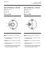
Gear and Bearing - Lubricate ...............................
Gear and Bearing - Lubricate ...............................
Gear and Bearing - Lubricate ...............................
Gear and Bearing - Lubricate ...............................
Hydraulic Fittings - Inspect ...................................
Wear Plates - Inspect/Replace .............................
Wear Tip - Inspect/Replace ..................................
35
36
40
43
44
44
45
45
46
58
60
Initial 20 Service Hours
Hub Nut - Check/Tighten ...................................... 46
Every 10 Service Hours or Daily
Rotator Head Bolts - Inspect ................................. 57
Initial 25 Service Hours
Jaw - Repair .......................................................... 46
Every 100 Service Hours
Rotator Head Bolts - Check .................................. 56
SEBU7420-08
35
Maintenance Section
Access Cover - Remove/Inspect
i02236649
Access Cover Remove/Inspect
i01439514
Bushings - Lubricate
SMCS Code: 6700-086
SMCS Code: 6344-011-AO; 6344-040-AO
Illustration 45
Illustration 44
g01029345
g00754434
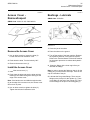
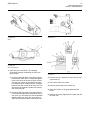
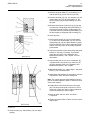
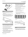
1. Close the jaw of the shear.
Remove the Access Cover
2. Place the shear on the ground.
1. Use an allen wrench to loosen the bolts (3).
Loosen the bolt until resistance is felt.
3. Turn off the engine of the host machine. Release
the hydraulic pressure in the hydraulic system.
Refer to the “Service Manual” of the host machine
for the proper procedure to release the hydraulic
pressure.
2. Push down the bolts. Turn the bolts by 180°.
3. Remove the access cover (1).
Install the Access Cover
1. Install the access cover (1).
2. Push down the bolts and turn the bolts until the
latches(2) are visible through the slots (4) at the
edge of the access cover.
Note: If the latches are not visible through the slots
(4) at the edge of the access cover, the access cover
will not lock in place.
3. Use an allen wrench to tighten the bolts (3).
Tighten the bolts until resistance is felt.
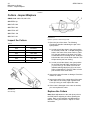
4. Clean the fittings with a clean rag before you
lubricate the fittings.
Note: In order to access the fittings on the pin for the
cutting jaw, you must remove two caps. There is one
cap on each side of the pin.
5. Lubricate the five grease fittings. There are two
fittings on the pivot pin for the cylinder (1). There
is one fitting on the end of the cylinder (2). There
are two fittings on the pin for the cutting jaw (3).
36
Maintenance Section
Cutters - Inspect/Replace
SEBU7420-08
i02236658
Cutters - Inspect/Replace
SMCS Code: 6801-040; 6801-510
S/N: BRD1-Up
S/N: CLE1-244
S/N: FDK1-344
S/N: CFW1-207
S/N: CDX1-124
S/N: CKY1-181
Illustration 47
Hydraulic cylinder for S320 through S390
Inspect the Cutters
Table 9
(1)
g00763257
Sales Model
Shear Locks
S305
199-8486(1)
S320
200-2959
S325
200-2960
S340
200-2885
S365
200-2961
S390
200-2962
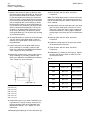
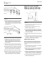
1. Open the jaw of the shear. The following
procedures describe maintaining the jaw in the
open position.
a. In order to hold the shear in the open position
for the S305, install 198-7100 Bar through the
holes in the frame of the shear. Refer to Table
9 for the part number of the shear lock. Refer
to Illustration 46 for installing the bar. Install the
bolts and the nuts on both ends of the bar. This
will prevent the jaw from closing.
b. In order to hold the shear in the open position
for the S320 through S390, install shear lock
(1) onto cover (3). The shear lock must be
installed behind guide block (2) for the cover.
Refer to Illustration 47. Refer to Table 9 for the
part numbers of the shear locks.
198-7100 Bar is a part of this group.
2. Inspect the cutters for wear or damage. Check the
cutters for cracks.
3. Inspect the radius of the cutting edge of the cutter.
If the radius of the cutting edge is greater than
5 mm (0.2 inch) you must replace the cutter.
4. If the cutter is damaged or the cutter is cracked,
you must replace the cutter.
Illustration 46
S305 Housing
g00778397
Replace the Cutters
Note: Make adjustments to the main pivot point on
the S305 before adjusting or before replacing the
cutters. Refer to the Operation and Maintenance
Manual, “Cutting Arm Preload - Adjust” for more
information.
SEBU7420-08
Illustration 48
37
Maintenance Section
Cutters - Inspect/Replace
g00778397
Illustration 50
g00756935
Illustration 51
g00777187
S305
Illustration 49
g00763257
S320 through S390
1. Open the jaw of the shear. The following
procedures describe maintaining the jaw in the
open position.
a. In order to hold the shear in the open position
for the S305, install 198-7100 Bar through the
holes in the frame of the shear. Refer to Table
9 for the part number of the shear lock. Refer
to Illustration 46 for installing the bar. Install the
bolts and the nuts on both ends of the bar. This
will prevent the hydraulic cylinder from raising
and closing the jaw.
b. In order to hold the shear in the open position
for the S320 through S390, install shear lock (1)
onto cover (3). The shear lock must be installed
behind guide block (2) for the cover. Refer to
Table 9 for the part numbers of the shear locks.
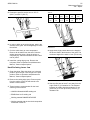
2. Remove bolts (1), washers (2), and nuts (3) from
guide blade (4).
3. Clean the threads of the bolts.
4. Remove guide blade (4) and shims (5).
5. Clean the surface of the guide blade and the
shims.
6. Remove the cutting edges from the upper jaw and
the lower jaw.
38
Maintenance Section
Cutters - Inspect/Replace
SEBU7420-08
7. Measure the amount of shims (5) that are under
the cutting edges and guide blade (4). Record the
amount of shims. Measure the amount of shims
(7) that are behind lock bushing (6). Record the
amount of shims. Cutting edges (8) and (9) at the
front of the jaws and guide blade (4) on the shear
jaw are equipped with a lock bushing (6). When
the thickness of shims (5) under guide blade (4)
is more than 2 mm (0.08 inch), you should mount
shims (7) behind lock bushing (6). The amount
of shims (7) is determined by subtracting 2 mm
(0.08 inch) of thickness from amount of shims
under guide blade (4). This will allow lock bushing
(6) to function properly.
13. Coat the bolts with 5P-3931 Anti-Seize
Compound.
8. Check guide blade (4). If there is an unused edge,
you can use the guide blade again. Clean all
surfaces of the guide blade. Grind any burrs on
the guide blade.
15. Coat the bolts with 5P-3931 Anti-Seize
Compound.
9. Inspect the pocket for the guide blade for any
wear or damage. If necessary, repair the jaw.
Refer to the Operation and Maintenance Manual,
“Jaw - Repair” for more information.
10. Inspect the pockets for the cutting edges for any
wear or damage. If necessary, repair the jaw.
Refer to the Operation and Maintenance Manual,
“Jaw - Repair” for more information.
Note: The cutting edges must be in front of the base
material for clearance. The cutting edges must be in
front of the base material in order to reduce the wear
of the material.
14. Install shims (10)in the lower jaw and in the upper
jaw. The shims must equal a minimum of 2 mm
(0.08 inch). Shims are used in order to adjust the
clearance between the cutting edges. Install the
cutting edges in the lower jaw. Do not install shims
(7).
16. Install the cutting edges in the upper jaw. Install
the shims that were removed.
17. Coat the bolts with 5P-3931 Anti-Seize
Compound.
18. Install bolts (1), washer (2), and nuts (3). Tighten
the bolts and the nuts. Refer to Table 10 for the
correct torque value.
Table 10
Torque values for the bolts for the cutting edges
Illustration 52
Sales Model
Bolt Size
Torque Value
S305
M12 x 1.75
105 ± 20 N·m
(75 ± 15 lb ft)
S320
M20 x 2.5
530 ± 70 N·m
(390 ± 50 lb ft)
S325
M20 x 2.5
530 ± 70 N·m
(390 ± 50 lb ft)
S330
M20 x 2.5
530 ± 70 N·m
(390 ± 50 lb ft)
S365
M20 x 2.5
530 ± 70 N·m
(390 ± 50 lb ft)
S390
M24 x 3.0
900 ± 100 N·m
(664 ± 74 lb ft)
g00757515
(S/N: BRD1-UP)
(S/N: CLE1-349)
(S/N: FDK1-449)
(S/N: CFW1-UP)
(S/N: CDX1-UP)
(S/N: CKY1-249)
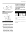
11. Inspect lower jaw (11) for wear. If dimension (A)
is greater than 5 mm (0.20 inch), lower jaw (11)
must be repaired. Refer to the Operation and
Maintenance Manual, “Jaw - Repair” for more
information.
12. Reinstall guide blade (4). Do not install shims (5).
SEBU7420-08
39
Maintenance Section
Cutters - Inspect/Replace
24. Measure the clearance between the cutting edge
(8) of the upper jaw and cutting edge (9) of the
lower jaw. The clearance between the two knives
must be less than 0.5 mm (0.02 inch). Use the
shims to adjust the amount of clearance. If the
amount of shims (10) under front knife (8) of the
upper jaw and front knife (9) of the lower jaw are
changed, then the amount of shims (7) behind
lock bushing (6) should be changed. Refer to
Illustration 51and 54.
Note: Refer to Table 11 for a guide to the clearance
between the cutters.
Illustration 53
g00763257
Table 11
Maximum Clearances Between the Cutters
19. Remove shear lock (1) from the cover (3).
20. Start the host machine.
Thickness of
material to cut
Cutter
Guide Cutter
Less than 6 mm
(0.23 inch)
0.5 mm
(0.02 inch)
1 mm (0.04 inch)
Greater than
6 mm (0.23 inch)
Less than 2 mm
(0.08 inch)
Less than 5 mm
(0.20 inch)
25. Remove the cutting edges and the guide blade.
26. Install the shims that are needed for the proper
clearance.
27. Install the cutting edges, the shims, and the bolts.
28. Coat the bolts with 5P-3931 Anti-Seize
Compound.
Illustration 54
g00757517
21. Slowly close the upper jaw. When the surface of
the cutters are close, stop the jaw.
22. Inspect the upper jaw for wear. If the dimension
(B) is greater than10 mm (0.4 inch), the upper jaw
(12) must be repaired. Refer to the Operation and
Maintenance Manual, “Jaw - Repair”.
23. Measure the clearance between the surface of
the upper jaw (12) and the guide blade (4). The
clearance between the surface of the upper jaw
(12) and guide blade (4) must be less than 1.0 mm
(0.04 inch). Use the shims to adjust the amount of
clearance. If the thickness of the shims is greater
than 5.0 mm (0.20 inch), the guide surface of
the upper jaw must be repaired. If the amount of
shims (5) under guide blade (4) is changed, then
the amount of shims (7) behind lock bushing (6)
should be changed. .
29. Tighten the bolts. Refer to Table 10 for the correct
torque value.
40
Maintenance Section
Cutters - Inspect/Replace
SEBU7420-08
i02237416
Cutters - Inspect/Replace
4. If the cutter is damaged or the cutter is cracked,
you must replace the cutter.
Replace the Cutters
SMCS Code: 6801-040; 6801-510
S/N: CLE245-Up
S/N: FDK345-Up
S/N: CFW208-Up
S/N: CDX125-Up
S/N: CKY182-Up
Inspect the Cutters
Table 12
Sales Model
Shear Locks
S320
200-2959
Illustration 56
S325
200-2960
Hydraulic cylinder for S320 through S390
S340
200-2885
S365
200-2961
S390
200-2961
1. Open the jaw of the shear. The following
procedures describe maintaining the jaw in the
open position.
g00763257
a. In order to hold the shear in the open position
for the S320 through S390, install shear lock
(1) onto cover (3). The shear lock must be
installed behind guide block (2) for the cover.
Refer to Table 12 for the part numbers of the
shear locks.
Illustration 55
g00763257
Hydraulic cylinder for S320 through S390
1. Open the jaw of the shear. The following
procedures describe maintaining the jaw in the
open position.
a. In order to hold the shear in the open position
for the S320 through S390, install shear lock
(1) onto cover (3). The shear lock must be
installed behind guide block (2) for the cover.
Refer to Table 12 for the part numbers of the
shear locks.
2. Inspect the cutters for wear or damage. Check the
cutters for cracks.
3. Inspect the radius of the cutting edge of the cutter.
If the radius of the cutting edge is greater than
5 mm (0.2 inch) you must replace the cutter.
Illustration 57
g01144127
SEBU7420-08
41
Maintenance Section
Cutters - Inspect/Replace
3. Remove the guide blade (7), the bushings (11),
and the shims (4) (5) from the lower jaw (18).
4. Remove the bolts (15) (16) , the washers (14), the
cutting edges (6) (10), the guide blade (7), the
shims (3) (4) (5) (9), and the bushings (11) from
the jaws.
5. Measure the amount of shims (3) (4) (5) (9) that
are under the cutting edges and guide blades (7).
Record the amount of shims. Cutting edges (6)
(10) at the front of the jaws and guide blades (7) on
the shear jaws are equipped with a bushing (11).
6. Clean all parts.
7. Check cutting edges (6) (10) and guide blades
(7). If there is an unused edge, you can use the
cutting edges (6) (10) and guide blades (7) again.
Clean all surfaces of the cutting edges and guide
blades. Grind any burrs on the cutting edge and
guide blades.
Illustration 58
g01144121
8. Inspect the pockets for the cutting edge and guide
blades for any wear of damage. If necessary,
repair the jaw. Refer to the Operation and
Maintenance Manual, “Jaw - Repair” for more
information.
9. Inspect lower jaw (11) for wear. If dimension (A)
is greater than 5 mm (0.20 inch), lower jaw (11)
must be repaired. Refer to the Operation and
Maintenance Manual, “Jaw - Repair”.
10. Reinstall bushings (11), cutting edges , and guide
blade (7). Do not install shims.
11. Install bolts and washers. Do not tighten. Coat the
bolts with 5P-3931 Anti-Seize Compound.
Note: The cutting edge and guide blades must be in
front of the base material in order to reduce the wear
of the base material.
12. Install shims in the lower jaw and in the upper
jaw. The shims must equal a minimum of 2 mm
(0.08 inch). Shims are used in order to adjust the
clearance between the cutting edges.
13. Coat the bolts with 5P-3931 Anti-Seize
Compound.
14. Tighten the bolts. Refer to Table 13 for the correct
torque value.
Illustration 59
g01144130
2. Remove bolts (13), and washers (14) from lower
jaw(18).
42
Maintenance Section
Cutting Arm Preload - Adjust
SEBU7420-08
Table 13
Torque values for the bolts for the cutting edges
Sales Model
Bolt Size
Torque Value
S305
M12 x 1.75
105 ± 20 N·m
(75 ± 15 lb ft)
S320
M20 x 2.5
530 ± 70 N·m
(390 ± 50 lb ft)
S325
M20 x 2.5
530 ± 70 N·m
(390 ± 50 lb ft)
S330
M20 x 2.5
530 ± 70 N·m
(390 ± 50 lb ft)
S365
M20 x 2.5
530 ± 70 N·m
(390 ± 50 lb ft)
S390
M24 x 3.0
900 ± 100 N·m
(664 ± 74 lb ft)
18. Inspect the upper jaw for wear. If the dimension
(B) is greater than10 mm (0.4 inch), the upper
jaw must be repaired. Refer to the Operation and
Maintenance Manual, “Jaw - Repair”.
19. Measure the clearance between the surface of the
upper jaw and the guide blade (7). The clearance
between the surface of the upper jaw and guide
blade must be less than 1.0 mm (0.04 inch). Use
the shims to adjust the amount of clearance. If
the thickness of the shims is greater than 5.0 mm
(0.20 inch), wear plate (17) must be replaced.
20. Measure the clearance between the cutting edge
(10) of the upper jaw and cutting edge (6) of the
lower jaw. The clearance between the surface of
the upper jaw and guide blade must be less then
0.5 mm (0.02 inch). Use the shims to adjust the
amount of clearance.
Note: Refer to Table 14 for a guide to the clearance
between the cutters.
Table 14
Maximum Clearances Between the Cutters
Illustration 60
g00763257
15. Remove shear lock (1) from the cover (3).
16. Start the host machine.
Thickness of
material to cut
Cutter
Guide Cutter
Less than 6 mm
(0.23 inch)
0.5 mm
(0.02 inch)
1 mm (0.04 inch)
Greater than
6 mm (0.23 inch)
Less than 2 mm
(0.08 inch)
Less than 5 mm
(0.20 inch)
21. Loosen bolts.
22. Install the shims that are needed for the proper
clearance.
23. Tighten the bolts. Refer to Table 13 for the correct
torque value.
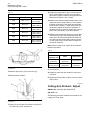
i01491459
Cutting Arm Preload - Adjust
SMCS Code: 6344-025-AN; 6349-025-ZP
S/N: BRD1-Up
The following procedure releases the preload for the
cutting arm of the shear.
Illustration 61
g01144340
17. Slowly close the upper jaw. When the surface of
the cutters are close, stop the jaw.
SEBU7420-08
43
Maintenance Section
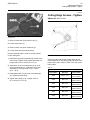
Cutting Edge Screws - Tighten
i01497449
Cutting Edge Screws - Tighten
SMCS Code: 6801-079-BC
Illustration 62
g00774447
1. Remove three bolts (2) that secure nut (1).
2. Loosen three bolts (3).
3. Remove three cone point setscrews (4).
4. Loosen three dog point setscrews (5).
Use the following steps in order to set the preload
on the cutting arm.
1. Install three dog point setscrews (5) into the frame
of the shear. Tighten the dog point setscrews to a
torque value of 55 ± 10 N·m (41 ± 7 lb ft).
2. Install three cone point setscrews (4) on top of
dog point setscrews (5). Tighten the cone point
setscrews to a torque value of 55 ± 10 N·m
(41 ± 7 lb ft).
3. Install three bolts (2) onto cone point setscrews
(4). Tighten the three bolts.
4. Tighten three bolts (3) to a torque value of
55 ± 10 N·m (41 ± 7 lb ft).
g00757261
Illustration 63
Check all of the bolts for the cutting edges for the
correct tightness. If necessary, tighten the bolts to the
proper torque value. Refer to Table 15 for the correct
torque value.
Table 15
Torque values for the bolts for the cutting edges
Sales Model
Bolt Size
Torque Value
S305
M12 x 1.75
105 ± 20 N·m
(75 ± 15 lb ft)
S320
M20 x 2.5
530 ± 70 N·m
(390 ± 50 lb ft)
S325
M20 x 2.5
530 ± 70 N·m
(390 ± 50 lb ft)
S330
M20 x 2.5
530 ± 70 N·m
(390 ± 50 lb ft)
S365
M20 x 2.5
530 ± 70 N·m
(390 ± 50 lb ft)
S390
M24 x 3.0
900 ± 100 N·m
(664 ± 74 lb ft)
44
Maintenance Section
Gear and Bearing - Lubricate
SEBU7420-08
i01695903
i01695921
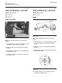
Gear and Bearing - Lubricate
Gear and Bearing - Lubricate
SMCS Code: 4055-086
SMCS Code: 4055-086
S/N: CFW1-Up
S/N: CKY1-Up
S/N: CDX1-Up
S340
S320 and S325
Illustration 65
Illustration 64
g00624790
Note: Wipe the fittings before you lubricate the
fittings.
1. Lubricate fitting (1). There is one fitting. The fitting
is located on the outside of the housing.
2. Rotate the shear for 120 degrees and lubricate
fitting (1).
3. Repeat Step 2. Grease will be evenly distributed
throughout the gear.
g00873526
Note: Wipe the fittings before you lubricate the
fittings.
1. Lubricate fitting (1). This fitting lubricates the gear.
The fitting is located to the left of the rotation
motor.
2. Rotate the shear for 120 degrees and lubricate
fitting (1).
3. Repeat Step 2. Grease will be evenly distributed
throughout the gear.
4. Lubricate the bearing. Fitting (2) is located near
the rotation motor.
Illustration 66
g00873533
4. Lubricate bearing (2). The lubrication point is
located 180° from the motor.
SEBU7420-08
45
Maintenance Section
Gear and Bearing - Lubricate
i01695935
i01695944
Gear and Bearing - Lubricate
Gear and Bearing - Lubricate
SMCS Code: 4055-086
SMCS Code: 4055-086
S/N: CLE1-244
S/N: CLE245-Up
S/N: FDK1-344
S/N: FDK345-Up
S365 and S390
S365 and S390
Illustration 67
g00872796
Illustration 68
g00872720
Note: Wipe the fittings before you lubricate the
fittings.
Note: Wipe the fittings before you lubricate the
fittings.
1. Lubricate the fittings (1). The fittings are located
by the rotation motors.
1. Lubricate the fittings (1). The fittings are located
by the rotation motors.
2. Rotate the shear for 120 degrees and lubricate
fittings (1).
2. Rotate the shear for 120 degrees and lubricate
fittings (1).
3. Repeat Step 2. Grease will be evenly distributed
throughout the gear.
3. Repeat Step 2. Grease will be evenly distributed
throughout the gear.
4. Lubricate bearing (2). The two lubrication points
for the bearing are located on the side of the
housing near the hydraulic connections.
4. Lubricate bearing (2). The two lubrication points
for the bearing are located on the side of the
housing near the hydraulic connections.
46
Maintenance Section
Hub Nut - Check/Tighten
SEBU7420-08
i02234280
i01446140
Hub Nut - Check/Tighten
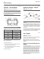
Hydraulic Fittings - Inspect
SMCS Code: 6344-527-NT; 6344-535-NT
SMCS Code: 5057-040-X6
NOTICE
Make sure to check the torque on the hub nuts prior
to cutting thin plate. Incorrect torque can lead to thin
plate jamming between the jaws of the shear. This can
cause damage to the work tool.
Illustration 70
g01029238
Illustration 69
Table 16
Inspect the hydraulic fittings for damage or for leaks.
You must repair all of the leaks or damage before you
use the work tool. If the work tool is not connected to
a host machine, the hydraulic lines must be capped
or plugged.
You must replace any damaged components before
you use the work tool. Consult your Caterpillar dealer
for replacement parts or for more information.
Sales Model
Part Number of Wrench
S305
169-7192
S320
169-7192
S325
169-7192
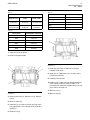
Jaw - Repair
S340
169-7192
SMCS Code: 6349-020
S365
169-7192
S390
201-8835
The play between the guide cutters should be less
than 1 mm (0.04 inch).
1. Remove lock bolt (1).
2. Check torque on hub nut (2). Torque on hub nut
(2) should be 300 N·m (220 lb ft).
3. If necessary, tighten the hub nut (2) to a torque
value of 300 N·m (220 lb ft).
4. Install lock bolt (1).
g00757222
i02236363
The shear jaw is adjusted in order to compensate for
the wear cutter during normal operation.
Note: Adjustment of the shear jaw should only be
performed after the cutters have been inspected and
changed.
Adjust the Clearance Between the
Cutters
Principle of Adjustment – After removing the hub
nuts and shims, any clearance between the individual
parts of the pivot point is removed by the use of
the hub nut and a steel ring on the drop side of the
shear. The hub nut on the side of the shear with
the cutter then pulls the cutters on the upper jaw
against the cutters on the lower jaw by moving the
jaw assembly. Once the jaw is in place, the jaw is
retained in position by shims that are placed on the
drop side of the shear.
SEBU7420-08
47
Maintenance Section
Jaw - Repair
Table 17
Table 19
Maximum Clearances Between the Cutters
Thickness of
material to cut
Cutter
Less than 6 mm
(0.23 inch)
0.5 mm
(0.02 inch)
Greater than
6 mm (0.23 inch)
Less than 2 mm
(0.08 inch)
Sales Model
Part Number of Ring (5)
S320
169-7193
S325
169-8915
1 mm (0.04 inch)
S340
195-0801
Less than 5 mm
(0.20 inch)
S365
197-7841
S390
201-8836
Guide Cutter
Table 18
Sales Model
Part Number of Wrench
S305
169-7192
S320
169-7192
S325
169-7192
S340
169-7192
S365
169-7192
S390
201-8835
1. Open the jaw of the shear.
2. Remove the guide blade.
Illustration 72
g00774816
7. Install ring (5). Refer to Table 19 for the part
numbers of the rings.
8. Install nut (2). Tighten the nut to a torque value
of 300 N·m (220 lb ft).
9. Carefully close the jaw.
10. Install nut (3). Tighten the nut until the clearance
of the cutters is correct. Refer to Table 17 for
recommended clearances. Install bolts (1) into nut
(3) in order to lock the nut.
11. Remove nut (2).
Illustration 71
g00774813
3. Remove lock bolts (1). Remove nut (3). Remove
nut (2).
4. Remove shims (4).
5. Install nut (2). In order to remove any play in the
joint, tighten the nut to a torque value of 300 N·m
(220 lb ft).
6. Remove nut (2).
12. Remove ring (5).
48
Maintenance Section
Jaw - Repair
SEBU7420-08
Hard Surfacing of the Shear
Jaws (S/N: BRD1-Up; CDX1-Up;
CFW1-Up; CKY1-249; CLE1-349;
FDK1-449)
Personal injury or death can result from fumes,
gases and ultraviolet rays from the weld arc.
Welding can cause fumes, burn skin and produce
ultraviolet rays.
Keep your head out of the fumes. Use ventilation,
exhaust at the arc, or both, to keep fumes and gases from your breathing area. Wear eye, ear and
body protection before working.
13. Measure Dimension (A). Dimension (A ) is the
amount of shims that is required.
Protect yourself and others; read and understand
this warning. Fumes and gases can be dangerous
to your health. Ultraviolet rays from the weld arc
can injure eyes and burn skin. Electric shock can
cause death.
14. Install shims (4). The shims should be even with
surface (6). The shims can be a maximum of
0.5 mm (0.02 inch) above surface (6).
Read and understand the manufacturer's instructions and your employer's safety practices. Do not
touch live electrical parts.
15. Install nut (2). Tighten nut (2) to a torque value of
300 N·m (220 lb ft). If necessary, turn nut (2) to
the next bolt hole.
See “American National Standard Z49.1, Safety in
Welding and Cutting” published by the American
Welding Society.
Illustration 73
g00774837
16. Install bolts (1).
17. Open the jaw.
18. Install the guide blade.
19. Carefully close the jaw.
20. Open the jaw.
21. Measure the clearance between the guide blade
and the upper jaw.
22. Install the proper amount of shims. Install the
guide blade.
American Welding Society
2501 N.W. 7th Street
Miami, Florida 33125
See “OSHA Safety and Health Standards, 29 CFR
1910”, available from U.S. Department of Labor.
U.S. Department of Labor
Washington, D.C. 20210
NOTICE
Before carrying out arc welding on the machine or on
any equipment attached to the machine, disconnect
all power and ground leads from the batteries in order
to avoid possible damage to electronic components.
23. Carefully close the jaw.
24. Open the jaw and close the jaw. Check the
clearance between the cutters. If necessary,
adjust the clearance. Refer to the Operation and
Maintenance Manual, “Cutter - Inspect/Replace”.
Personal injury can result from flame cutting or
welding on painted areas.
The effect of gasses from burned paint is a hazard
to the person doing the cutting or welding.
Do not flame cut or weld on painted areas.
SEBU7420-08
49
Maintenance Section
Jaw - Repair
Table 20
Sales Model
Part Number of Shear
Lock (1)
S305
199-8486
S320
200-2959
S325
200-2960
S340
200-2885
S365
200-2961
S390
200-2962
g00777348
Illustration 75
Illustration 74
g00763257
1. Open the jaw of the shear. In order to hold the
shear in the open position, install shear lock (1)
onto cover (3). The shear lock must be installed
behind guide block (2) for the cover. Refer to Table
22 for the part numbers of the shear locks.
(4)
(5)
(6)
(7)
(8)
(9)
Upper jaw
Surface of the upper jaw
Guide surface of the upper jaw
Template
Reference surface
Front plate
2. Grind surface (5) of the upper jaw. The surface
should be clean and free of rust.
3. Preheat surface (5) of the nose of the upper jaw to
150 °C (302 °F) to 200 °C (392 °F).
4. These items are recommended for the hard
surfacing of the material:
• LINCOLN Wearshield ME welding rod
• ESAB Wear Arc-5 welding rod
• Welding material DIN8555 MF6-55GP
• Welding material with the chemical composition
mentioned in table 23
Table 21
C
(%)
Mn
(%)
Si
(%)
Cr
(%)
Mo
(%)
Hardness
Hrc
0.5 0.8
0.6 1.0
0.6 1.0
4.5 6.5
0.8 1.2
56 - 61
5. Weld a closed bed of beads on the nose of the
upper jaw. Lay one bead lengthwise next to the
previous bead.
6. Use template (7) in order to check guide surface
(6) of the upper jaw.
50
Maintenance Section
Jaw - Repair
SEBU7420-08
a. Place template (7) against reference surface
(8) of the cutter.
b. Slide template (7) along reference surface (8)
until template (7) is even with rear surface (6)
of the nose of the upper jaw.
c. If necessary, grind the nose of the jaw until the
nose of the jaw matches the template.
d. Front plate (9) of the jaw must be even with the
front surface of the template. If front plate (9) is
not even with the front surface of the template,
the upper jaw must be rewelded.
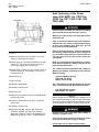
Hard Surfacing of the Shear Jaws
(S/N: CKY250-Up; CLE350-Up;
FDK450-Up)
Personal injury or death can result from fumes,
gases and ultraviolet rays from the weld arc.
Welding can cause fumes, burn skin and produce
ultraviolet rays.
Keep your head out of the fumes. Use ventilation,
exhaust at the arc, or both, to keep fumes and gases from your breathing area. Wear eye, ear and
body protection before working.
Protect yourself and others; read and understand
this warning. Fumes and gases can be dangerous
to your health. Ultraviolet rays from the weld arc
can injure eyes and burn skin. Electric shock can
cause death.
Read and understand the manufacturer's instructions and your employer's safety practices. Do not
touch live electrical parts.
Illustration 76
g00562487
Front plate
7. If the front plate is worn, weld the front plate.
Weld the front plate in the pattern that is shown
in illustration 76. Space the welds at (B) 50 mm
(2 inches) intervals. Use the welding material
DIN8555 MF6-55GP.
See “American National Standard Z49.1, Safety in
Welding and Cutting” published by the American
Welding Society.
American Welding Society
2501 N.W. 7th Street
Miami, Florida 33125
See “OSHA Safety and Health Standards, 29 CFR
1910”, available from U.S. Department of Labor.
U.S. Department of Labor
Washington, D.C. 20210
NOTICE
Before carrying out arc welding on the machine or on
any equipment attached to the machine, disconnect
all power and ground leads from the batteries in order
to avoid possible damage to electronic components.
Personal injury can result from flame cutting or
welding on painted areas.
The effect of gasses from burned paint is a hazard
to the person doing the cutting or welding.
Do not flame cut or weld on painted areas.
SEBU7420-08
51
Maintenance Section
Jaw - Repair
Table 22
Sales Model
Part Number of Shear
Lock (1)
S305
199-8486
S320
200-2959
S325
200-2960
S340
200-2885
S365
200-2961
S390
200-2962
g00777348
Illustration 78
Illustration 77
g00763257
1. Open the jaw of the shear. In order to hold the
shear in the open position, install shear lock (1)
onto cover (3). The shear lock must be installed
behind guide block (2) for the cover. Refer to Table
22 for the part numbers of the shear locks.
(4)
(5)
(6)
(7)
(8)
(9)
Upper jaw
Surface of the upper jaw
Guide surface of the upper jaw
Template
Reference surface
End wear plate
2. Grind surface (5) of the upper jaw. The surface
should be clean and free of rust.
3. Preheat surface (5) of the nose of the upper jaw to
150 °C (302 °F) to 200 °C (392 °F).
4. These items are recommended for the hard
surfacing of the material:
• LINCOLN Wearshield ME welding rod
• ESAB Wear Arc-5 welding rod
• Welding material DIN8555 MF6-55GP
• Welding material with the chemical composition
mentioned in table 23
Table 23
C
(%)
Mn
(%)
Si
(%)
Cr
(%)
Mo
(%)
Hardness
Hrc
0.5 0.8
0.6 1.0
0.6 1.0
4.5 6.5
0.8 1.2
56 - 61
5. Weld a closed bed of beads on the nose of the
upper jaw. Lay one bead lengthwise next to the
previous bead.
6. Use template (7) in order to check guide surface
(6) of the upper jaw.
52
Maintenance Section
Jaw - Repair
SEBU7420-08
a. Place template (7) against reference surface
(8) of the cutter.
b. Slide template (7) along reference surface (8)
until template (7) is even with rear surface (6)
of the nose of the upper jaw.
c. If necessary, grind the nose of the jaw until the
nose of the jaw matches the template.
d. End wear plate (9) of the jaw must be even
with the front surface of the template. If the
end wear plate (9) is not even with the front
surface of the template, the upper jaw must be
rewelded.
7. If the end wear plates are worn, replace end
wear plates with new end wear plates. Refer
to Operation and Maintenance Manual, “End
Wear Plates - Inspect/Replace” for the proper
procedure.
Note: New end wear plate contains cracks, due to
the hardness of the material.
Guide Surface of the Upper
Jaw (S/N: BRD1-Up; CDX1-124;
CFW1-207; CKY1-181; CLE1-244;
FDK1-344)
4. Grind the welded area to a smooth finish.
5. Use template (3) in order to check guide surface
(2) of the upper jaw.
a. Hold reference surface (A) of the template
against cutter (1).
b. Slide template (3) along cutter (1) until
reference surface (B) contacts the upper jaw.
c. Measure clearance (C). Measure the clearance
along cutter (1). The clearance must be even
along cutter (1). The clearance must not be
more than 1 mm (0.04 inch). If the clearance is
greater than 1 mm (0.04 inch), guide surface
(2) must be welded again.
6. Install the guide cutter and adjust the clearance.
7. Allow the work tool to cool completely before you
use the work tool.
Guide Surface of the Upper Jaw
(S/N: CDX125-Up; CFW208-Up;
CKY182-Up; CLE245-Up;
FDK345-Up)
On these shears, the guide surface of the upper jaw
is replaced by a wear plate.
Reference: Refer to Operation and Maintenance
Manual, “Cutters - Inspect/Replace” for more
information on replacing the wear plate.
Build up the Upper Jaw
1. Clean the shear.
2. Place the shear in a horizontal position. Open the
jaw.
Illustration 79
g00774841
(1) Cutter in upper jaw
(2) Guide surface on upper jaw
(3) Template
(A) Reference surface of template
(B) Reference surface of template
1. Grind guide surface (2) of the upper jaw. The
surface should be clean and free of rust.
2. Preheat guide surface (2) of the upper jaw to
150 °C (302 °F) to 200 °C (392 °F).
3. In order to weld the jaw, use welding material AWS
A5.28-96: ER100S-G. Weld guide surface (2).
3. Lock the jaw in an open position. Refer to
Operation and Maintenance Manual, “Cutters
inspect/replace” for more information.
SEBU7420-08
53
Maintenance Section
Jaw - Repair
2. Place the shear in a horizontal position. Open
the jaw. Lock the jaw in the open position.
Refer to Operation and Maintenance, “Cutters
inspect/replace” for more information.
3. Remove the cutting edge group. Remove the paint
from the surface of the jaw, that is needed to be
built up. Grind the surface.
4. These items are recommended for the hard
surfacing of the material:
• LINCOLN Wearshield ME welding rod
Illustration 80
g01138269
4. Remove the cutting edge group. Remove the
paint from the surface of the jaw, that is needed
to be built up.
5. Grind the surfaces. Use AWS A5.28-96:
ER100D-G electrode to repair the area. Preheat
the specific area of repair to a minimum of 150 °C
(302 °F) and no higher than 200 °C (392 °F).
• ESAB Wear Arc-5 welding rod
• Welding material DIN8555 MF6-55GP
• Welding material with the chemical composition
mentioned in table 23
Table 24
C
(%)
Mn
(%)
Si
(%)
Cr
(%)
Mo
(%)
Hardness
Hrc
0.5 0.8
0.6 1.0
0.6 1.0
4.5 6.5
0.8 1.2
56 - 61
5. Preheat the specific area of repair to a minimum
of 150 °C (302 °F) and no higher than 200 °C
(392 °F).
Illustration 81
g01137931
6. Build up original shape. Weld in the direction of
the grain. Use a straightedge to check the surface.
7. Cool the weld slowly to room temperature.
Remove all the debris from the weld .
Illustration 82
8. Paint the welded area with primer. Allow the
primer to dry completely. Paint the welded area
with a final coat of paint.
6. Apply three single passes along the length of
the shear. Weld in the direction of the grain. The
maximum height of the weld is 3 mm (0.12 inch).
9. Install the cutting edge group . Remove the lock
jaws. Refer to Operation and Maintenance, “Cutter
inspect/replace” for more information.
Hard surfacing the Upper Jaw
1. Clean the shear.
g01137938
54
Maintenance Section
Jaw - Repair
SEBU7420-08
Repair the Lower Jaw (S/N:
BRD1-Up; CLE1-349; FDK1-449;
CFW1-Up; CDX1-Up; CKY1-249)
Illustration 83
g01137942
7. Start the first pass at least 7 mm (0.28 inch) away
from the edge. Refer to (z) illustration 83. The
distance between the welds should be between
15 mm (0.59 inch) to 25 mm (0.98 inch). Refer to
(y) illustration 83.
Illustration 85
g00757515
1. Clean area (A) of the lower jaw that needs to be
repaired. Remove any rust.
2. Preheat area (A) of the lower jaw to 150 °C
(302 °F) to 200 °C (392 °F).
3. In order to weld the lower jaw, use the welding
material AWS A5.28-96: ER100S-G. Weld the
inside of the lower jaw until area (A) that was worn
away is present again.
4. Grind the welds until the surface of the lower jaw
is flat.
Illustration 84
g01137970
8. Stagger the ends of the weld. The length of the
welds should be offset by 50 mm (1.97 inch).
Refer to (x) illustration 84. The Hard surface
should end approximately at 150 mm (5.91 inch)
from the radius.
9. Taper the ends of welds into the base material
with grind marks going in the direction of the grain.
10. Cool the weld slowly to temperature. Remove all
the debris from the weld. Paint the welded area
with primer. Allow the primer to completely dry.
5. These shears have the guide surface of the lower
jaw which is replaced by two cutting edges. (S/N:
CKY250-Up; CLE350-Up; FDK450-Up)
Build up the Lower Jaw
Note: If a jaw build up is required build up the
jaw. The Hard surfacing of the jaw should only be
performed when the hard surfacing of the jaw is
required.
1. Clean the shear. Place the shear on a horizontal
position. Rotate the shear 180 °.
11. Paint the welded area with a final coat of paint.
2. Open the jaw. Lock the jaw in the open position.
Refer to Operation and Maintenance Manual,
“Cutters inspect/replace”.
12. Install the cutting edge group. Remove lock jaws.
Refer to Operation and Maintenance Manual,
“Cutters inspect/replace” for more information.
3. Remove all components of the cutting edge group.
Remove paint from the surface of the jaw that
needs to be built up. Grind the needed surfaces.
4. Use the welding material AWS A5.28-96: ER
100S-G to repair the area.
SEBU7420-08
55
Maintenance Section
Jaw - Repair
5. Preheat the specific service area to 150 °C
(302 °F) to 200 °C (392 °F).
Illustration 86
Table 25
C
(%)
Mn
(%)
Si
(%)
Cr
(%)
Mo
(%)
Hardness
Hrc
0.5 0.8
0.6 1.0
0.6 1.0
4.5 6.5
0.8 1.2
56 - 61
g01132601
6. In order to build up the original shape, weld in the
direction of the grain. Use a straightedge to check
the surface.
7. Cool the weld slowly to room temperature.
Remove all the debris from the weld. Paint the
welded area with primer. Allow the primer to
completely dry. Paint the welded area with a final
coat of primer.
Illustration 87
g01132737
4. Apply three single passes that run the length of
the shear. Weld in the direction of the grain. The
maximum height of the weld is 3 mm (0.118 inch).
8. Install the cutting edge group. Remove the
lock jaws. Refer to Operation and Maintenance
Manual, “Cutters inspect/replace”.
Hard Surfacing Lower Jaw
1. Clean the shear. Place the shear in a horizontal
position. Open the jaw. Lock the jaw in the open
position. Refer to Operation and Maintenance
Manual, “Cutters inspect/replace”.
2. Remove the cutting edge group. Remove paint
from the surface of the jaw that needs to be
welded. Grind surfaces.
3. These items are recommended for the hard
surfacing of the material:
• LINCOLN Wearshield ME welding rod
• ESAB Wear Arc-5 welding rod
• Welding material DIN8555 MF6-55GP
• Welding material with the chemical composition
mentioned in table 23
Illustration 88
g01137256
5. Start the first pass at least 7 mm away from the
edge. Refer to (r) illustration 88. The distance
between the welds should be between 15 mm
(0.59 inch) to 25 mm (0.98 inch). Refer to (s)
illustration 88.
56
Maintenance Section
Rotator Head Bolts - Check
Illustration 89
SEBU7420-08
g01137266
6. Stagger the ends of the welds. The length of the
welds should be offset 50 mm (1.97 inch). Refer
to (t) illustration 89.
7. The hard surface should end approximately at
150 mm (5.91 inch) from the radius. Taper the
ends of the welds into the base material with
marks from grinding going with the grain.
8. Cool the weld slowly to room temperature.
9. Remove all the debris from the weld. Paint the
welded area with primer. Allow the primer to
completely dry. Paint the welded area with a final
coat of paint.
10. Install the cutting edge group. Remove the
lock jaws. Refer to Operation and Maintenance
Manual, “Cutters inspect/replace”.
i02241319
Rotator Head Bolts - Check
SMCS Code: 6326-535-BC
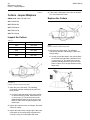
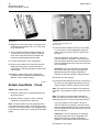
1. Position the work tool in an upright position just
above the ground.
2. Stop the machine engine in order to prevent
inadvertent movement of the work tool.
Note: The host machine must be equipped with a
boom lowering control valve in order to perform this
procedure. If the host machine is not equipped with a
boom lowering control valve, contact your Caterpillar
dealer.
Illustration 90
g01005368
(1) Rotator head bolt (outer ring)
(2) Cover plug
3. Check the static inspection torque of all 36 bolts
(1) in the outer ring. Use appropriate tooling in
order to apply a torque of 270 N·m (200 lb ft) to
the bolts.
The bolt should not move before a torque of
270 N·m (200 lb ft) is reached. If the bolt moves,
then the sealant has been broken and the bolt has
been overstressed. All bolts in the outer ring must
then be replaced.
Reference: For more information on replacing
the rotator head bolts, refer to Operation and
Maintenance Manual, “Rotator Head Bolts Replace” for the work tool that is being serviced.
4. Remove the cover plug (2).
5. Check the static inspection torque of all 34 bolts in
the inner ring. Use appropriate tooling in order to
apply a torque of 270 N·m (200 lb ft) to the bolts.
Note: The work tool can be placed in two positions
in which it is not possible to mount a bolt to the inner
ring.
Note: The work tool can be rotated manually in
order to access the 34 bolts of the inner ring. Use a
sufficiently long lever in order to rotate the work tool.
The bolt should not move before a torque of
270 N·m (200 lb ft) is reached. If the bolt moves,
then the sealant has been broken and the bolt has
been overstressed. All bolts in the inner ring must
then be replaced.
Reference: For more information on replacing
the rotator head bolts, refer to Operation and
Maintenance Manual, “Rotator Head Bolts Replace” for the machine that is being serviced.
6. Replace the cover plug.
SEBU7420-08
57
Maintenance Section
Rotator Head Bolts - Inspect
i02241336
i02241379
Rotator Head Bolts - Inspect
Rotator Head Bolts - Replace
SMCS Code: 5060; 6326-040-BC; 6326
SMCS Code: 6326-510-BC
1. Position the work tool in an upright position just
above the ground.
1. Position the work tool in an upright position just
above the ground.
2. Stop the machine engine in order to prevent
inadvertent movement of the work tool.
2. Stop the machine engine in order to prevent
inadvertent movement of the work tool.
Note: The host machine must be equipped with a
boom lowering control valve in order to perform this
procedure. If the host machine is not equipped with a
boom lowering control valve, contact your Caterpillar
dealer.
Note: The host machine must be equipped with a
boom lowering control valve in order to perform this
procedure. If the host machine is not equipped with a
boom lowering control valve, contact your Caterpillar
dealer.
Illustration 91
g01004467
3. Check the rotator head bolts (1) on the outer ring.
If any bolts are missing the heads, replace all the
bolts in the outer ring.
4. Remove the cover plug (2) in order to access the
rotator head bolts on the inner ring. Only one
rotator head bolt will be visible at a time.
5. Check the rotator head bolts on the inner ring. If
any bolts are missing the heads, replace all the
bolts in the inner ring.
Note: The work tool can be rotated manually in order
to view all of the rotator head bolts. Use a sufficiently
long lever in order to rotate the work tool.
Illustration 92
g01005664
(1) Rotator head bolt (outer ring)
(2) Cover plug
3. Repeat Steps 4 through 11 for all of the bolts on
the outer ring.
4. Remove the bolt.
5. Mechanically remove the old sealant.
6. Clean the threaded hole.
7. Clean the new bolt.
Reference: For more information on replacing
the rotator head bolts, refer to Operation and
Maintenance Manual, “Rotator Head Bolts Replace” for the machine that is being serviced.
Illustration 93
g01004413
58
Maintenance Section
Wear Plates - Inspect/Replace
SEBU7420-08
8. Put 155-0695 Thread Lock Compound over the
whole threaded length of the new bolt.
9. Mount the new bolt in the threaded hole.
10. Use appropriate tooling in order to apply a torque
of 270 N·m (200 lb ft) to the bolt.
11. Put a marking on the bolt that has been replaced.
1. Open the jaw of the shear. The following
procedures describe maintaining the jaw in the
open position.
a. In order to hold the shear in the open position,
install shear lock (1) onto cover (3). The shear
lock must be installed behind guide block (2) for
the cover. Refer to Illustration 94. Refer to Table
26 for the part numbers of the shear locks.
12. Remove the cover plug (2).
13. Repeat Steps 4 through 11 for all of the bolts on
the inner ring.
Note: At two positions of the work tool, it is not
possible to mount a bolt to the inner ring.
Note: The work tool can be rotated manually in
order to access the 34 bolts of the inner ring. Use a
sufficiently long lever in order to rotate the work tool.
i02274417
Wear Plates - Inspect/Replace
SMCS Code: 6801-040; 6801-510; 6820-040;
6820-510
(S/N: CKY1-Up; CLE1-Up; FDK1-Up)
Inspect the Wear Plates
Table 26
Sales Model
Shear Locks
S340
200-2885
S365
200-2961
S390
200-2962
Illustration 94
Hydraulic cylinder for S320 through S390
(1) Shear lock
(2) Guide block
(3) Cover
Illustration 95
g01139129
2. Inspect wear plates (K, L, M) for excessive wear
or damage. Check wear plates for cracks.
g00763257
SEBU7420-08
59
Maintenance Section
Wear Plates - Inspect/Replace
Replace the Wear Plates
g00763257
Illustration 96
S320 through S390
(1) Shear lock
(2) Guide block
(3) Cover
1. Open the jaw of the shear. The following procedure
describes maintaining the jaw in the open position.
a. In order to hold the shear in the open position,
install shear lock (1) onto cover (3). The shear
lock must be installed behind guide block (2) for
the cover. Refer to Illustration 96. Refer to Table
26 for the part numbers of the shear locks.
2. Grind the existing wear plates (K, L, M) in order to
remove the wear plates.
3. Grind the surface of the end plate (Z). The surface
should be clean and free of rust.
4. Remove the paint from the end plate (Z).
Table 27
SHEAR
S340
S365
S390
(A)(mm)
35
70
150
(B)(mm)
20
30
50
20
30
(C)(mm)
(D)(mm)
150
(E)(mm)
35
Illustration 97
(H)(mm)
25
5. Tack weld the new wear plates (K, L, M) to the
end plate (Z) of the housing (Y). Check for proper
positioning. Refer to table 27 for dimensions
and part numbers of the wear plates. Refer to
illustration 97 for dimensions and part numbers
of the wear plates.
Wear Plate
(K)
235-0916
(2x)
Wear Plate
(L)
234-5067
(1x)
Wear Plate
(m)
235-0916
(2x)
234-5067
(3x)
235-0915
(2x)
g01139184
6. Preheat the surface of the end plate (Z) to 150 °C
(302 °F) to 200 °C (392 °F).
7. In order to weld the wear plate (K, L, M), use
welding material AWS A5.28-96: ER100S-G.
60
Maintenance Section
Wear Tip - Inspect/Replace
SEBU7420-08
8. Cool the weld slowly to room temperature.
9. Remove all debris from the welds. Paint the
welded area with primer. Allow primer to
completely dry.
10. Paint the welded area with a final coat of paint.
11. Remove lock jaws. Refer to Operation and
maintenance manual, “Cutters Inspect/Replace”.
1. Open the jaw of the shear. The following
procedures describe maintaining the jaw in the
open position.
a. In order to hold the shear in the open position
for the S320 through S390, install shear lock
(1) onto cover (3). The shear lock must be
installed behind guide block (2) for the cover.
Refer to Illustration 98. Refer to Table 28 for
the part numbers of the shear locks.
i02270537
Wear Tip - Inspect/Replace
SMCS Code: 6801-040; 6801-510; 6829-040;
6829-510
S/N: CLE245-Up
S/N: FDK345-Up
S/N: CFW208-Up
S/N: CDX125-Up
g00859809
S/N: CKY182-Up
Illustration 99
Inspect the Wear Tip
2. Inspect wear tip (5) for excessive wear or damage.
Check wear tip (5) for cracks.
Table 28
Sales Model
Shear Locks
S320
200-2959
S325
200-2960
S340
200-2885
S365
200-2961
S390
200-2962
Replace the Wear Tip
Illustration 100
g00763257
S320 through S390
(1) Shear lock
(2) Guide block
(3) Cover
Illustration 98
Hydraulic cylinder for S320 through S390
(1) Shear lock
(2) Guide block
(3) Cover
g00763257
1. Open the jaw of the shear. The following procedure
describes maintaining the jaw in the open position.
a. In order to hold the shear in the open position
for the S320 through S390, install shear lock
(1) onto cover (3). The shear lock must be
installed behind guide block (2) for the cover.
Refer to Illustration 100. Refer to Table 28 for
the part numbers of the shear locks.
SEBU7420-08
Illustration 101
61
Maintenance Section
Wear Tip - Inspect/Replace
g00859809
2. In order to prevent damage to cutting edge (4),
remove cutting edge (4) from the upper jaw.
3. Grind existing wear tip (5) in order to remove wear
tip (5).
4. After you remove the old wear tip, grind the
surface of the upper jaw. The surface should be
clean and free of rust.
g00861464
Illustration 103
(6) Template
(7) Reference surface
6. Place template (6) against reference surface (7)
in order to determine the location of the new wear
tip. Place the new wear tip onto the upper jaw of
the shear.
7. Tack weld the new wear tip to the upper jaw of the
shear. Check for proper positioning.
8. Preheat the surface of the nose of the upper jaw
to 150 °C (302 °F) to 200 °C (392 °F).
Table 29
Illustration 102
g00878756
(D) 40 degrees
(E) 10 mm (0.39 inch) for the S320 through S365 shears and
12 mm (0.47 inch) for the S390 shear
5. Grind a bevel to width (E) with an angle (D) on the
nose of the upper jaw in order to create a space
for welding the wear tip onto the upper jaw.
Sales
Model
Wear Tip
Welding
Height (X)
Welding
Height (Y)
S320
217-5055
12 mm
(0.4724
inch)
4 mm
(0.1575
inch)
S325
218-0033
14 mm
(0.5512
inch)
5 mm
(0.1969
inch)
S340
218-0034
14 mm
(0.5512
inch)
5 mm
(0.1969
inch)
S365
218-0035
16 mm
(0.6299
inch)
7 mm
(0.2756
inch)
S390
218-0036
20 mm
(0.7874
inch)
7 mm
(0.2756
inch)
62
Maintenance Section
Wear Tip - Inspect/Replace
SEBU7420-08
Procedure for the Buildup and Hard
Surfacing of the Wear Tip(S/N:
CDX1-Up; CFW1-Up; CKY1-Up;
CLE1-Up; FDK1-Up)
Personal injury or death can result from fumes,
gases and ultraviolet rays from the weld arc.
Welding can cause fumes, burn skin and produce
ultraviolet rays.
Keep your head out of the fumes. Use ventilation,
exhaust at the arc, or both, to keep fumes and gases from your breathing area. Wear eye, ear and
body protection before working.
Illustration 104
g00872862
(A) Hard surfacing
(B) Bevel groove weld
(C) Fillet
9. In order to weld the wear tip, use welding material
AWS A5.28-96: ER100S-G. Weld the wear tip
onto the upper jaw. Refer to Illustration 104. Refer
to Table 29 for the height of each weld for each
shear.
10. Grind the surface flat with the shape of the upper
jaw.
11. Once the jaw has cooled, install cutting edge (4).
Protect yourself and others; read and understand
this warning. Fumes and gases can be dangerous
to your health. Ultraviolet rays from the weld arc
can injure eyes and burn skin. Electric shock can
cause death.
Read and understand the manufacturer's instructions and your employer's safety practices. Do not
touch live electrical parts.
See “American National Standard Z49.1, Safety in
Welding and Cutting” published by the American
Welding Society.
American Welding Society
2501 N.W. 7th Street
Miami, Florida 33125
See “OSHA Safety and Health Standards, 29 CFR
1910”, available from U.S. Department of Labor.
U.S. Department of Labor
Washington, D.C. 20210
Personal injury can result from flame cutting or
welding on painted areas.
The effect of gasses from burned paint is a hazard
to the person doing the cutting or welding.
Do not flame cut or weld on painted areas.
Buildup of the Wear Tip
1. Clean shear.
SEBU7420-08
63
Maintenance Section
Wear Tip - Inspect/Replace
2. Place the shear in a horizontal position. Open the
upper jaw (C). Lock the upper jaw (C) in the open
position. Refer to Operation and Maintenance
Manual, “Cutter Inspect/Replace”.
3. Inspect wear tip (B) for excessive wear or
excessive damage.
4. Check wear tip (B) for cracks.
Note: Replace wear tip (B) if excessive damage,
wear, or cracks are noticed. Refer to Operation and
Maintenance Manual, “Wear Tip Inspect/Replace”.
5. Remove the paint from the surface of the upper
jaw (C), that is needed to be buildup.
Illustration 106
g01142055
The side of the shear with the wear plate
6. Grind surfaces.
7. Use the welding material AWS A5.2896:ER100S-G to repair the area.
10. Repeat step 5 through 9 for the wear plate (G)
side. Weld in the direction of the grain. refer to
illustration 106.
8. Preheat the specific area to a minimum of 150 °C
(302 °F) and no higher than 200 °C (392 °F).
Note: The wear tip (B) must be flush with the wear
plate (G).
Hard Surfacing the Wear Tip
Illustration 105
g01142044
The side of the shear with the cutting edge
Illustration 107
9. Build up original shape. Weld in the direction of the
grain. Refer to illustration 105. Use a straightedge
(A) to check the surface. Refer to illustration 105.
Note: The wear tip (B) must be flush with cutting
edges (D).
g01142065
Template
1. Remove all the debris from the welds. Grind
surface (5).
2. The procedure for the hard surfacing needs the
following items:
• Lincoln Wear Shield ME welding rod
• ESAB Wear Arc-5 welding rod
• Welding material DIN8555 MF6-55GP
• Welding material with chemical composition
mentioned in 30
64
Maintenance Section
Wear Tip - Inspect/Replace
SEBU7420-08
Table 30
C
(%)
Mn
(%)
Si
(%)
Cr
(%)
Mo
(%)
Hardness
Hrc
0,50,8
0,61,0
0,61,0
4,56,5
0,81,2
56-61
3. Preheat the specific service area to 150 °C
(302 °F) to 200 °C (392 °F). Weld a closed bed
of beads in surface (5). Lay one bead lengthwise
next to the previous bead.
4. Weld in the direction of the grain. Refer to
illustration 107.
5. Cool the weld slowly to room temperature.
Remove all the debris from the welds.
6. Use template (Z) in order to check the surface (5)
of the upper jaw (C). Refer to illustration 107.
7. Place template (Z) along reference surface (8)
until template (Z) is even with surface (6) of the
nose of the upper jaw (C). If necessary, grind the
nose of the upper jaw (C) until the nose of the
upper jaw (C) matches the template.
8. Unlock the upper jaw (C). Refer to Operation and
Maintenance Manual, “Cutters Inspect/Replace”.
Carefully close the upper jaw.
Illustration 108
g01142280
checking the fit
9. Check the fit (H) of the wear tip (B) into the shear
housing (K). Grind the surface, if necessary. Lock
the upper jaw (C) in the open position. Refer to
Operation and Maintenance Manual, “Cutters
Inspect/Replace”.
10. Paint the welded area with primer. Allow the
primer to completely dry. Paint the welded area
with a final coat of paint. Remove the lock on
the upper jaw (C). Refer to Operations and
Maintenance Manual, “Cutters Inspect/Replace”.