1
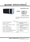
Order No. MOD12 0837 8C E
Microwave Oven
Model No. NN-ST342M
25L
Silver
Latin America
s
NN-ST342M(RPM)
Power Requirement
220 Volts AC 50 & 60Hz
1,270 Watts (5.9A(50Hz)) /(6.2A(60Hz))
Single phase, 3 wire grounded
NN-ST342M(RPH)
120 Volts AC 60 Hz
1,270 Watts (10.3 A)
Single phase, 3 wire grounded
Power Output
800 Watts full microwave power (IEC60705)
Microwave Frequency
2,450 MHz
Magnetron
2M219J
Timer
0 ~ 99 min. and 50 sec.
Outside Dimensions
485(W) x 287 (H) x 400(D) mm
Cavity Dimensions
315(W) x 227(H) x 349 (D) mm
Net Weight
12.7kg (approx.)
Shipping weight
13.7 kg (approx.)
Specifications subject to change without notice.
© Panasonic Corporation 2012 Unauthorized
copying and distribution is a violation of law
WARNING
This product should be serviced only by trained qualified personnel. This service manual covers products for following markets. When troubleshooting or replacing parts, please refer to the country identifications shown below for your applicable product specification. ……For Panama, Mexico
……For Peru, Chile
RPM
RPH
SAFETY PRECAUTIONS
This device is to be serviced only by properly qualified service personnel.
Consult the service manual for proper service procedures to assure continued safety operation and for precautions to be
taken to avoid possible exposure to excessive microwave energy.
PRECAUTIONS TO BE OBSERVED BEFORE AND
DURING SERVICING TO AVOID POSSIBLE
EXPOSURE TO EXCESSIVE MICROWAVE ENERGY
A) Do not operate or allow the oven to be operated with the door open.
B) Make the following safety checks on all ovens to be serviced before activating the magnetron or other
microwave source, and make repairs as necessary; (1) interlock operation, (2) proper door closing, (3)
seal and sealing surfaces (arcing, wear, and other damage), (4) damage to or loosening of hinges and
latches, (5) evidence of dropping or abuse.
C) Before turning on microwave power for any service test or inspection within the microwave generating
compartments, check the magnetron, wave guide or transmission line, and cavity for proper alignment,
integrity, and connections.
D) Any defective or misadjusted components in the interlock, monitor, door seal, and microwave generation
and transmission systems shall be repaired, replaced, or adjusted by procedures described in this manual
before the oven is released to the owner.
E) A microwave leakage check to verify compliance with the Federal Performance Standard should be
performed on each oven prior to release to the owner.
CAUTION
MICROWAVE RADIATION
DO NOT BECOME EXPOSED TO RADIATION FROM THE MICROWAVE GENERATOR
OR OTHER PARTS CONDUCTING MICROWAVE ENERGY.
CONTENTS
(Page)
SAFETY PRECAUTIONS - - - - - - - - - - - - - - - - - - - - - - - - - - - - - - - - - - - - - - - - - - - - - - - - - - - - - - - - - - - - - - - - - - - - - Inside front cover
SPECIFICATIONS - - - - - - - - - - - - - - - - - - - - - - - - - - - - - - - - - - - - - - - - - - - - - - - - - - - - - - - - - - - - - - - - - - - - - - - - - - - - - - - - - - - - - - - - - - - - - - - - - - - - - 1-1
CAUTIONS - - - - - - - - - - - - - - - - - - - - - - - - - - - - - - - - - - - - - - - - - - - - - - - - - - - - - - - - - - - - - - - - - - - - - - - - - - - - - - - - - - - - - - - - - - - - - - - - - - - - - - - - - - - - - - 2-1
INSTALLATIONS - - - - - - - - - - - - - - - - - - - - - - - - - - - - - - - - - - - - - - - - - - - - - - - - - - - - - - - - - - - - - - - - - - - - - - - - - - - - - - - - - - - - - - - - - - - - - - - - - - - - - - 3-1
OPERATING INSTRUCTIONS - - - - - - - - - - - - - - - - - - - - - - - - - - - - - - - - - - - - - - - - - - - - - - - - - - - - - - - - - - - - - - - - - - - - - - - - - - - - - - - - - - - - 4-1
FEATURES- - - - - - - - - - - - - - - - - - - - - - - - - - - - - - - - - - - - - - - - - - - - - - - - - - - - - - - - - - - - - - - - - - - - - - - - - - - - - - - - - - - - - - - - - - - - - - - - - - - - - - - - - - - - - - - - - - - - - - - - 4-1
CONTROL PANEL - - - - - - - - - - - - - - - - - - - - - - - - - - - - - - - - - - - - - - - - - - - - - - - - - - - - - - - - - - - - - - - - - - - - - - - - - - - - - - - - - - - - - - - - - - - - - - - - - - - - - - - - - - - - - - 4-1
OPERATING SEQUENCE- - - - - - - - - - - - - - - - - - - - - - - - - - - - - - - - - - - - - - - - - - - - - - - - - - - - - - - - - - - - - - - - - - - - - - - - - - - - - - - - - - - - - - - - - - - - - - - - - - - - 4-2
SCHEMATIC DIAGRAM - - - - - - - - - - - - - - - - - - - - - - - - - - - - - - - - - - - - - - - - - - - - - - - - - - - - - - - - - - - - - - - - - - - - - - - - - - - - - - - - - - - - - - - - - - - - - - - - - - - - - - 4-3
CIRCUIT DESCRIPTION - - - - - - - - - - - - - - - - - - - - - - - - - - - - - - - - - - - - - - - - - - - - - - - - - - - - - - - - - - - - - - - - - - - - - - - - - - - - - - - - - - - - - - - - - - - - - - - - - - - - - 4-4
SERVICE INFORMATION - - - - - - - - - - - - - - - - - - - - - - - - - - - - - - - - - - - - - - - - - - - - - - - - - - - - - - - - - - - - - - - - - - - - - - - - - - - - - - - - - - - - - - - - - - 5-1
TOOLS AND MEASURING INSTRUMENTS - - - - - - - - - - - - - - - - - - - - - - - - - - - - - - - - - - - - - - - - - - - - - - - - - - - - - - - - - - - - - - - - - - - - - - - - - - - 5-1
MICROWAVE LEAKAGE TEST - - - - - - - - - - - - - - - - - - - - - - - - - - - - - - - - - - - - - - - - - - - - - - - - - - - - - - - - - - - - - - - - - - - - - - - - - - - - - - - - - - - - - - - - - - - - 5-1
MEASUREMENT OF MICROWAVE POWER OUTPUT - - - - - - - - - - - - - - - - - - - - - - - - - - - - - - - - - - - - - - - - - - - - - - - - - - - - - - - - - - - 5-3
DISASSEMBLY AND ADJUSTMENT - - - - - - - - - - - - - - - - - - - - - - - - - - - - - - - - - - - - - - - - - - - - - - - - - - - - - - - - - - - - - - - - - - - - - - - - - - - - - - - - - - - - - 5-3
INTERLOCK CONTINUITY TEST- - - - - - - - - - - - - - - - - - - - - - - - - - - - - - - - - - - - - - - - - - - - - - - - - - - - - - - - - - - - - - - - - - - - - - - - - - - - - - - - - - - - - - - - - - 5-7
COMPONENT TEST PROCEDURE - - - - - - - - - - - - - - - - - - - - - - - - - - - - - - - - - - - - - - - - - - - - - - - - - - - - - - - - - - - - - - - - - - - - - - - - - - - - - - - - - - - - - - 5-8
TROUBLE SHOOTING - - - - - - - - - - - - - - - - - - - - - - - - - - - - - - - - - - - - - - - - - - - - - - - - - - - - - - - - - - - - - - - - - - - - - - - - - - - - - - - - - - - - - - - - - - - - - - - - - - - - - - 5-12
EXPLODED VIEW - - - - - - - - - - - - - - - - - - - - - - - - - - - - - - - - - - - - - - - - - - - - - - - - - - - - - - - - - - - - - - - - - - - - - - - - - - - - - - - - - - - - - - - - - - - - - - - - - - - - - 6-1
REPLACEMENT PARTS LIST - - - - - - - - - - - - - - - - - - - - - - - - - - - - - - - - - - - - - - - - - - - - - - - - - - - - - - - - - - - - - - - - - - - - - - - - - - - - - - - - - - - - 7-1
SCHEMATIC DIAGRAM OF P.C.B. - - - - - - - - - - - - - - - - - - - - - - - - - - - - - - - - - - - - - - - - - - - - - - - - - - - - - - - - - - - - - - - - - - - - - - - - - - - - - - 8-1
POWER LEVEL & ACCESSORIES
ITEM
Control Complement
DESCRIPTION
Microwave Power for Variable Cooking
Power level
800 Watts
550 Watts
440 Watts
HGigh
MGedium
Med
220 Watts
80 Watts
DeGfrost
I
LGow
Rating Label Location
Inside
Accessories
Instruction manual
Glass Tray
Roller Ring
This microwave oven is designed for household use only.
It is not recommended for commercial purposes.
1-1
CAUTIONS
Unlike other appliances, the microwave oven is
high-voltage and high-current equipment.
Though it is free from danger in ordinary use,
extreme care should be taken during repair.
MICROWAVE RADIATION
Personnel should not be exposed to the
microwave energy which may radiate from the
magnetron or other microwave generating
device if it is improperly used or connection.
All input and output microwave connections,
waveguide, flange and gasket must be secure
never operate the device without a microwave
energy absorbing load attached.
Never look into an open waveguide or antenna
while the device is energized.
• DO NOT operate on a 2-wire extension cord during
repair and use.
• NEVER TOUCH any oven components or wiring during
operation.
• BEFORE TOUCHING any parts of the oven, always
remove the power plug from the outlet.
• For about 30 seconds after the oven stops, an electric
charge remains in the high voltage capacitor. When
replacing or checking, you must discharge the high
voltage capacitor by shorting across the two terminals
with an insulated screwdriver.
• Proper operation of the microwave oven requires that
the magnetron be assembled to the waveguide and
cavity. Never operate the magnetron unless it is
properly installed.
• Be sure that the magnetron gasket is properly
installed around the dome of the tube whenever
installing the magnetron.
ANTENNA
GASKET
COOLING FIN
FILAMENT
TERMINALS
MAGNETRON
CHASSIS GROUND
MAGNETRON
• Remove your watches whenever working close to or
replacing the Magnetron.
• NEVER operate the oven with no load.
• NEVER injure the door seal and front plate of the oven
cavity.
• NEVER put iron tools on the magnetron.
• NEVER put anything into the latch hole and the
interlock switches area.
THE OVEN IS TO BE SERVICED ONLY
BY PROPERLY QUALIFIED SERVICE
PERSONNEL.
2-1
INSTALLATIONS
BEFORE YOU BEGIN, READ THE FOLLOWING INSTRUCTIONS COMPLETELY AND CAREFULLY.
INSTALLING
EARTHING INSTRUCTIONS
1. Empty the microwave oven and clean inside it with
a soft, damp cloth. Check for damage such as
misaligned door, damage around the door or dents
inside the cavity or on the exterior.
This microwave oven is designed to be used in a fully
earthed condition.
It is imperative, therefore, to make sure it is properly
earthed before servicing
2. Put the oven on a counter, table, or shelf that is
strong enough to hold the oven and the food and
utensils you put in it. (The control panel side of the
oven is the heavy side. Use care when handling.)
WARNINGTHIS APPLIANCE
MUST BE EARTHED
3. Do not block the vent and the air intake openings.
Blocking vent or air intake openings can cause
damage to the oven and poor cooking results.
Make sure the microwave oven legs are in place to
ensure proper air flow.
IMPORTANT
The wires in this mains lead are colored in
accordance with the following code:
4. The oven should not be installed in any area where
heat and steam are generated, because they may
damage the electronic or mechanical parts of the
unit.
Do not install the oven next to a conventional
surface unit or above a conventional wall oven.
Green-and-yellow:
Blue:
Brown:
Earth
Neutral
Live
As the colors of the wires in the mains lead of this
appliance may not correspond with the colored
markings identifying the terminals in your plug,
proceed as follows.
5. Use microwave oven in an ambient temperature
less than 104°F(40°C).
6. Place the microwave oven on a sturdy and flat
surface at least 10 cm(4 inches) from the wall.
The wire which is colored green-and-yellow must be
connected to the terminal in the plug which is marked
with the letter E or by the earth symbol ( ) or
colored green or green-and-yellow.
7. Place the microwave oven as far away as possible
from TV, RADIO, COMPUTER, etc., to prevent
interference.
The wire which is colored blue must be connected to
the terminal in the plug which is marked with the letter
N or colored black.
The wire which is colored brown must be connected
to the terminal in the plug which is marked with the
letter L or colored red.
10cm
3-1
OPERATING INSTRUCTIONS
FEATURES
Oven Front Plate
See-Through oven window
Door C
Control Panel
Safety Door Lock System
Glass Tray
Roller Ring
CONTROL PANEL
NN- ST342M(RPM)
(1)
(2)
(3)
(4)
(5)
(6)
(7)
(8)
(9)
Display Window
Micro Power Pad
Time Pads
Turbo Defrost Pads
Auto Reheat Pad
Auto Cook Pads
Serving/Weight Pad
Timer/Clock Pad
Stop/Reset Pad
Before cooking: One tap clears all your instructions.
During cooking: One tap temporarily stops the cooking
process. Another tap cancels all your instructions and
colon or time of day appears in the display window.
(10) Start Pad
After cooking program setting, one tap allows oven to begin
functioning. If door is opened or Stop/Reset Pad is pressed
once during oven operation, Start Pad must be pressed again
to restart oven.
(1)
(2)
(3)
(4)
(5)
(6)
Beep Sound:
When a pad is pressed correctly, a beep will be heard.
If a pad is pressed and no beep is heard, the unit did
not or cannot accept the instruction. The oven will beep
twice between programmed stages. At the end of any
complete program, the oven will beep 5 times.
(7)
(8)
(9)
(10)
4-1
CONTROL PANEL
NN- ST342M(RPH)
(2)
(3)
(1)
(6)
(5)
(4)
(7)
(8)
(1)
(2)
(3)
(4)
(5)
(6)
(7)
(8)
(9)
Tecla de Palomitas de maiz
Tecla de Recalentamiento Automático
Tecla de Cocción Automática
Tecla de Potencia
Tecla de Descongelación Automática
Tecla de Porciones/Peso
Tecla de Minuto Automático
Tecla de Más/Menos
Teclas numéricas
(10) Tecla de Cronómetro
(11) Tecla de Reloj
(12) Tecla de
Pausa/Cancelar
Antes de Cocinar: Un toque habilita sus instrucciones.
Durante la cocción: Un toque detiene temporalmente el proceso de
cocción. Otro toque cancela todas sus instrucciones y la hora del día
aparece en la pantalla.
(9)
(11)
(10)
(13) Tecla de Encender
Un toque permite al horno empezar su función. Si la puerta está abierta
o la tecla Pausa/Cancelar se oprime una vez durante la operación del
horno, la tecla de Encender debe oprimirse otra vez para reanudar el
trabajo del horno.
Bip:
(12)
(13)
Cuando una tecla es presionada correctamente, se
escuchará un “bip”. Si una tecla es presionada y no
escucha un “bip significa que la”,unidad no aceptó o
no pudo aceptar la instrucción. El horno hará 2 veces
“bip” entre las etapas programadas. Al final de cada
programa completado, el horno hará 5 veces “bip”.
OPERATING SEQUENCE
The following is a description of component functions
during oven operation.
4. AUTO WEIGHT DEFROST
Stop/
Cancel
1. SETTING THE CLOCK
Stop/
Cancel
Clock
Set the time
by pressing
time pads
Desired
defrost
program
Desired
weight
5. AUTO WEIGHT REHEAT
Clock
Stop/
Cancel
NOTE: You can set 24 hour clock.
Desired
reheat
program
Desired
weight
2. CANCEL FUNCTION
Touch the Stop/Cancel pad whenever you need to
cancel an entry or a function currently in use.
The display will either return to the last item entered
or to the clock.
6. CHILD LOCK
This oven has a CHILD LOCK feature
• TO SET CHILD LOCK
• Press start pad three times
L appear in the display.
3. MICROWAVE COOKING
Stop/
Cancel
Desired
cooking power
Desired
cooking time
Start
• TO CANCEL CHILD LOCK
• Press stop/cancel pad three times
L disappears.
Start
4-2
Start
SCHEMATIC DIAGRAM
4-3
CIRCUIT DESCRIPTION
power of microwave oven as POWER LEVEL.
(refer to page 1-1)
GENERAL DETAILS
• The low voltage transformer supplies the necessary
voltage to the micom controller when power cord is
plugged in.
• When the door is closed, the primary switch is ON, the
secondary switch is ON, and the monitor switch opens
(contact COM and NO).
WHEN THE DOOR IS OPENED DURING
COOKING
• Both the primary switch and relay 2 are cut off primary
winding voltage of the high voltage transformer.
• ON-OFF of relay 2 is coupled electrically with opening
and closing of the secondary switch.
• When the door is opened, the secondary switch is
opened and when the door is closed, the secondary
switch is closed.
• The cooking time stops counting down.
• Relay stops functioning.
• As the door is opened, if the contact of primary switch
and relay 2 and/or secondary switch fails to open, the
fuse opens due to the large current surge caused by
the monitor switch activation, which in turn stops
magnetron oscillation.
WHEN SELECTING COOKING POWER
LEVEL AND TIME
• The micom controller memorizes the function you set.
• The time you set appears in the display window.
• Each indicator light turns on to indicate that the stage
has been set.
WHEN TOUCHING THE START PAD
• The coil of the relay is energized by the micom
controller.
• Power input is supplied to the high voltage transformer
through the fuse to the primary switch and relay 2.
• Turntable rotates.
FUSE
FUSE
PRIMARY
SWITCH
L
PRIMARY
SWITCH
MONITOR
SWITCH
L
TRANSFORMER
N
MONITOR
SWITCH
TRANSFORMER
N
RELAY 2
MICOM CONTROLLER
RELAY 2
SECONDARY
SWITCH
MICOM CONTROLLER
• The fan motor rotates and cools the magnetron by
blowing the air (coming from the intake on the
backplate).
• The air is also directed into the oven to exhaust the
vapor in the oven through the left side.
• Cooking time starts counting down.
• 3.2 volts AC is generated from the filament winding of
the high voltage transformer. This 3.2 volts is applied to
the magnetron to heat the magnetron filament through
two noise-preventing choke coils.
• A high voltage of approximately 2100 volts AC is
generated in the secondary of the high voltage
transformer which is increased by the action of the high
voltage diode and charging of the high voltage
capacitor.
• The negative 4000 Volts DC is applied to the filament
of the magnetron.
WHEN THE OVEN IS SET AT ANY LEVEL
EXCEPT MAXIMUM.
• The micom controller controls the ON-OFF time of relay
2 by the applied signal to vary the average output
4-4
SECONDARY
SWITCH
SERVICE INFORMATION
TOOLS AND MEASURING INSTRUMENTS
NECESSARY TOOLS
NECESSARY MEASURING INSTRUMENTS
Tools normally used for TV servicing are sufficient.
Standard tools are listed below.
• Diagonal pliers
• Long nose pliers
• Phillips screwdriver
• Flat blade screwdriver
• Wrench (size 5mm)
• Nutdriver (size 5mm)
• Adjustable wrench
• Soldering iron
• Solder
• Vinyl insulation tape
• Polishing cloth
• TESTER(VOLTS-DC, AC., Ohmmeter)
• Microwave survey meter
- Holaday HI-1500
HI-1501
- Narda 8100
8200
• Inch scale
• 600 cc non conductive material beaker (glass or plastic),
inside diameter: approx. 8.5 cm(31/2 in.)
• Cylindrical and made of borosilicate glass vessel.
max. thickness: 3 mm
outside diameter: approx. 190mm
height: approx. 90mm
• Glass thermometer: 100°C or 212°F (1 deg scale)
MICROWAVE LEAKAGE TEST
CAUTIONS
MEASURING MICROWAVE ENERGY
LEAKAGE
• Be sure to check microwave leakage prior to
servicing the oven if the oven is operative prior to
servicing.
• The service personnel should inform the
manufacture importer, or assembler of any
certified oven unit found to have a microwave
emission level in excess of 5 mW/cm2 and should
repair any unit found to have excessive emission levels
at no cost to the owner and should ascertain the cause
of the excessive leakage. The service personnel
should instruct the owner not to use the unit until the
oven has been brought into compliance.
• If the oven operates with the door open, the service
personnel should:
- Tell the user not to operate the oven.
- Contact the manufacturer.
• The service personnel should check all surface and
vent openings for microwave leakage.
• Check for microwave leakage after every servicing.
The power density of the microwave radiation leakage
emitted by the microwave oven should not exceed
4 mW/cm2. Always start measuring of an unknown field
to assure safety for operating personnel from radiation
leakage.
• Pour 275±15cc of 20±5°C(68±9°F) water in a beaker
which is graduated to 600 cc, and place the beaker
on the center of the turntable.
• Set the energy leakage monitor to 2450 MHz and
use it following the manufacturer's recommended
test procedure to assure correct result.
• When measuring the leakage, always use the 2inch (5cm) spacer supplied with the probe.
• Operate the oven at its maximum output.
• Measure the microwave radiation using and
electromagnetic radiation monitor by holding the
probe perpendicular to the surface being measured
Move probe along shaded area
Probe scanning speed
Less than 2.5 cm/sec
( 1in/sec)
5-1
MEASUREMENT WITH OUTER CASE
REMOVED
NOTES WHEN MEASURING
• Do not exceed meter full scale deflection.
• The test probe must be removed no faster than
1 inch/sec (2.5 cm/sec) along the shaded area,
otherwise a false reading may result.
• The test probe must be held with the grip portion of the
handle.
A false reading may result if the operator's hand is
between the handle and the probe.
• When testing near a corner of the door, keep the probe
perpendicular to the surface making sure the probe
horizontally along the oven surface, this may possibly
cause probe damage.
• When you replace the magnetron, measure for
microwave energy leakage before the outer case is
installed and after all necessary components are
replaced or adjusted.
Special care should be taken in measuring the
following parts. (Circled area of below Fig.)
- Around the magnetron
- The waveguide
WARNING : AVOID CONTACTING ANY
HIGH VOLTAGE PARTS
RECORD KEEPING AND NOTIFICATION
AFTER MEASUREMENT
• After adjustment and repair of any microwave energy
interruption or microwave energy blocking device,
record the measured values for future reference. Also
enter the information on the service invoice.
• The microwave energy leakage should not be more
than 4 mW/cm2.sq. after determining that all parts are
in good condition, functioning properly and genuine
replacement parts which are listed in this manual have
been used.
• At least once a year, have the electromagnetic energy
leakage monitor checked for calibration by its
manufacturer.
MEASUREMENT WITH A FULLY
ASSEMBLED OVEN
• After all components, including the outer case, are fully
assembled, measure for microwave energy leakage
around the door viewing window, the exhaust opening,
and air inlet openings.
• Microwave energy leakage must not exceed the values
prescribed below.
NOTE: Leakage with the outer case removedless than
5 mW/cm2.sq. Leakage for a fully assembled
oven (Before the latch switch (primary) is
interrupted) with the door in a slightly opened
position-less than 2 mW/cm2.sq.
5-2
MEASUREMENT OF MICROWAVE POWER OUTPUT
• Microwave power output measurement is made with
the microwave oven supplied at its rated voltage and
operated at its maximum microwave power setting with
a load of (1000±5) g of potable water.
• The water is contained in a cylindrical borosilicate glass
vessel having a maximum material thickness of 3 mm
and an outside diameter of approximately 190mm.
• The oven and the empty vessel are at ambient
temperature prior to the start of the test.
• The initial temperature (T1) of the water is (10±2)°C. It
is measured immediately before the water is added to
the vessel. After addition of the water to the vessel,
the load is immediately placed on the center of the
turntable which is in thd lowest position and the
microwave power switched on.
• The time T for the temperature of the water to rise by a
value ∆ T of (10±2)°K is measured, where T is the time
in seconds and ∆T is the temperature rise. The initial
and final water temperatures are selected so that the
maximum difference between the final water
temperature and the ambient temperature is 5°K.
• The microwave power output P in watts is calculated
from the following formula :
is measured while the microwave generator is
operating at full power. Magnetron filament heat-up
time is not included. (about 3 sec)
• The water is stirred to equalize temperature throughout
the vessel, prior to measuring the final water
temperature.
• Stirring devices and measuring instruments are
selected in order to minimize addition or removal of
heat.
WATER LOAD
TURNTABLE
NOTES:
For simple tests of micromave power output, conduct
it by heating one litre water for one minute,
minimum temperature rise should be 6 °C
4187 x (∆T) + 0.55 X (T2 - T0 ) X M
P=
T
• T2: Temperature after heating
• T0: Temperature of bowl
• M: Weight of bowl
DISASSEMBLY AND ADJUSTMENT
A. OUTER CASE REMOVAL
C. CONTROL PANEL ASSEMBLY
1) Disconnect the leadwire from the Timer motor
2) Remove the screws for securing the control panel.
3) Lift control panel ASS ’Y from the oven by the tab
unhooked.
1) Disconnect the power supply cord from the outlet.
2) Remove the screws from the rear and along side
edges of the case.
The outer case must be moved backward to be lifted
off.
B. POWER SUPPLY CORD
1) Remove the outer case.
2) Disconnect two terminals, and remove one screw of
the earth terminal.
CAUTION: DISCHARGE THE HIGH VOLTAGE
CAPACITOR BEFORE SERVICING
(refer to page 2-1)
5-3
D. DOOR ASSEMBLY REMOVAL
E. HIGH VOLTAGE TRANSFORMER
REMOVAL
1) Open the door.
2) Remove two screws holding the Hinge
to the Cavity Ass'y.
CAUTION : Be careful not to damage Door C
by screwdriver.
3) Lift up and pull the door.
1) Discharge the high voltage capacitor.
2) Disconnect the leadwire from magnetron, high voltage
transformer, and capacitor.
3) Remove the screw holding the high voltage
transformer to the baseplate.
NOTE:
1. After replacing the door, be sure to check that the
primary switch, monitor switch, and secondary switch
operate normally.
2. After replacing the door, check for microwave energy
leakage with a survey meter. Microwave energy must
be below the limit of 5 mW/cm2. (with a 275 ml water
load)
3. When mounting the door assembly to the oven
assembly, be sure to adjust the door assembly parallel
to the chassis. Also adjust so the door has no play
between the inner door surface and oven frame
assembly. If the door assembly is not mounted
properly, microwaves may leak from the clearance
between the door and the oven.
F. ORIFICE ASSEMBLY REMOVAL
1) Discharge the high voltage capacitor.
2) Disconnect the leadwire from fan motor, noise filter
and high voltage capacitor.
3) Remove the two screws holding the orifice ASS’Y
to the oven cavity and remove the high voltage diode
earth screw.
4) Remove the screw of the capacitor bracket.
5) Remove the two screws holding the fan motor ASS’Y
to the Orifice ASS’Y.
G. HIGH VOLTAGE CAPACITOR AND
DIODE REMOVAL
1) Discharge the high voltage capacitor.
2) Disconnect the leadwire from fan motor, noise filter
and high voltage capacitor.
3) Remove the screw holding the Orifice
the oven
earth screw.
4) Remove the screw holding the high voltage capacitor
bracket.
Remove door Assembly
Remove door Assembly
5-4
H. AIR GUIDE ASSEMBLY REMOVAL
J. REMOVING THE TURNTABLE MOTOR
1) Disconnect the leadwire from lamp, A.C Relay and
monitor resistor and magnetron.
2) Remove the screw to the cavity.
1) Remove the glass tray.
2) Remove the pully shaft VERY CAREFULLY
3) Lay the unit down on its back.
4) Remove the turntable motor cover.
The turntable base cover is easily removed by
pinching the six parts with a wire cutting.
5) Disconnect the leadwire from the turntable motor
terminals.
6) Remove the screw securing the turntable motor to
the oven cavity ASS’Y
7) After replacing the motor, rotate the removed
turntable motor cover.
8) Fit the turntable motor cover’s projecting part to the
base plate slit.
I. MAGNETRON REMOVAL
1) Disconnect the leadwire from the high voltage
transformer and high voltage capacitor.
2) Remove the air guide.
3) Carefully remove the mounting screws holding the
magnetron and the waveguide.
4) Remove the magnetron until the tube is
clear from the waveguide.
NOTE:
1. When removing the magnetron, make sure its
dome does not hit any adjacent parts, or it may be
damaged.
2. When replacing the magnetron, be sure to install
the magnetron gasket in the correct position and
be sure that the gasket is in good condition.
3. After replacing the magnetron, check for microwave
leakage with a survey meter around the
magnetron. Microwave energy must be below the
limit of 5 mW/cm2. (With a 275 ml. water load).
Make sure that gasket is rigidly attached to the
magnetron. To prevent microwave leakage, tighten the
mounting screws properly, making sure there is no gap
between the waveguide and the magnetron.
NOTE:
1. Remove the wire lead from the turntable motor
VERY CAREFULLY.
2. Be sure to grasp the connector, not the wires, when
removing
Base plate
Magnetron
Magnetron
Magnetron
Gasket
Waveguide
Bracket
Dome
Waveguide
5-5
K. PCB ASSEMBLY REMOVAL
L. INTERLOCK SYSTEM
1) Remove the control panel assembly from the
cavity.
2) Remove screws which hold the PCB to the
control panel.
3) Disconnect the flat cable from the PCB and
take off the PCB .
1) INTERLOCK MECHANISM
The door lock mechanism is a device which has
been specially designed to eliminate completely
microwave activity when the door is opened during
cooking and thus to prevent the danger resulting
from the microwave leakage.
2) MOUNTING OF THE PRIMARY/MONITOR/
SECONDARY SWITCHES TO THE LATCH
BOARD
ADJUSTMENT
DIRECTION
S03
PRIMARY
SWITCH
C
MONITOR
SWITCH
SECONDARY
SWITCH
3) INSTALLATION AND ADJUSTMENT OF THE
LATCH BOARD TO THE OVEN ASSEMBLY
• Mount the latch board to the oven assembly.
• Adjust the latch board in the arrow direction so that
oven door will not have any play in it when the door
is closed.
• Tighten the mounting screw.
• Check for play in the door by pushing the door
release button. Door movement should be less
than 0.5 mm. (1/64 inch)
Don't push the door release button while making
adjustment. Make sure that the latch moves
smoothly after adjustment are completed and that
the screws are tight. Make sure the primary, monitor,
and secondary switches operate properly by
following the continuity test procedure.
FIG. 1
CAUTION: CHECK THE CORRECT POSITION
MAGNETRON
H.V. TRANSFORMER
H.V.
DIODE
H.V. CAPACITOR
PRIMARY
5-6
INTERLOCK CONTINUITY TEST
WARNING : FOR CONTINUED PROTECTION AGAINST EXCESSIVE RADIATION
EMISSION, REPLACE ONLY WITH IDENTICAL REPLACEMENT PARTS.
TYPE NO. KW3A FOR SWITCHS
B. SECONDARY INTERLOCK SWITCH TEST
A. PRIMARY INTERLOCK SWITCH TEST
Disconnect the wire lead from the secondary
switch.
Connect the ohmmeter leads to the common
(COM) and normally open (NO) terminals of the
switch. The meter should indicate a open circuit in
the door open condition. When the door is closed,
meter should indicate an closed circuit. When the
secondary switch operation is abnormal, make the
necessary adjustment or replace the switch only
with the same type of switch.
When the door release button is depressed slowly
with the door closed, an audible click should be
heard at the same time or successively at
intervals. When the button is released slowly, the
latches should activate the switches with an
audible click.
If the latches do not activate the switches when
the door is closed, the switches should be a
adjusted in accordance with the adjustment
procedure. Disconnect the wire lead from the
primary switch. Connect the ohmmeter leads to
the common (COM) and normally open (NO)
terminal of the switch. The meter should indicate
an open circuit in the door open condition.
When the door is closed, the meter should
indicate a closed circuit.
When the primary switch operation is abnormal,
make the necessary adjustment or replace the
switch only with the same type of switch.
COMPONENTS
SWITCHES
(Wire leads removed)
C. MONITOR SWITCH TEST
Disconnect the wire lead from the monitor switch.
Connect the ohmmeter leads to the common
(COM) and normally closed (NC) terminals of the
switch. The meter should indicate closed circuit in
the door open condition. When the door is closed,
meter should indicate an open circuit. When the
monitor switch operation is abnormal, replace with
the same type of switch.
NOTE: After repairing the door or the interlock
system, it is necessary to do this continuity
test before operating the oven.
TEST PROCEDURE
Check for continuity of the
switch with an Ohm-meter
Primary
Switch
RESULTS
Door
open
NO
COM
Type No.KW3A
Monitor
Switch
NC
COM
Type No.KW3A
Secondary
Switch
NO
COM
Type No.KW3A
NOTE : After checking for the continuity of switches, make sure that are
correctly connected.
5-7
Door
closed
COMPONENT TEST PROCEDURE
CAUTIONS
1. DISCONNECT THE POWER SUPPLY CORD FROM THE OUTLET WHENEVER REMOVING THE
OUTER CASE FROM THE UNIT. PROCEED WITH THE TEST ONLY AFTER DISCHARGING THE HIGH
VOLTAGE CAPACITOR AND REMOVING THE WIRE LEADS FROM THE PRIMARY WINDING OF THE
HIGH VOLTAGE TRANSFORMER. (SEE PAGE 2-1)
2. ALL OPERATIONAL CHECKS WITH MICROWAVE ENERGY MUST BE DONE WITH A LOAD (1 LITER
OF WATER IN CONTAINER) IN THE OVEN.
COMPONENTS
TEST PROCEDURE
RESULTS
HIGH VOLTAGE
TRANSFORMER
(Wire leads removed)
FILAMENT
WINDING
TERMINAL
SECONDARY
WINDING
PRIMARY
TERMINAL
1. Measure the resistance.
(Ohm-meter scale: Rx1)
• Primary winding
• Secondary winding
• Filament winding
Approx.: 1.4 ohm
Approx.: 90 ohm
Less than: 1 ohm
2. Measure the resistance.
(Ohm-meter scale: Rx1000)
• Primary winding to ground
• Filament winding to ground
Normal: Infinite
Normal: Infinite
MAGNETRON
(Wire leads removed)
1. Measure the resistance.
(Ohm-meter scale: Rx1)
• Filament terminal
Normal: Less than 1 ohm
2. Measure the resistance.
(Ohm-meter scale: Rx1000)
• Filament to chassis
Normal: Infinite
5-8
COMPONENTS
TEST PROCEDURE
RESULTS
Antenna
Gasket
Chassis
Filament
NOTE: When testing the magnetron, be sure to install the magnetron gasket
in the correct position and be sure that the gasket is in good condition.
HIGH VOLTAGE
CAPACITOR
HIGH VOLTAGE
DIODE
Measure the resistance.
(Ohm-meter scale: Rx1000)
• Terminal to terminal.
Normal: Momentarily indicates
several ohms, and then
gradually returns to
10M ohms.
Measure the resistance.
(Ohm-meter scale: Rx1000)
• Terminal to case.
Normal: ∞
Measure the continuity (Forward).
(Ohm-meter scale: Rx10000)
Normal: Continuity.
Abnormal: ∞ *
Measure the continuity (Reverse).
(Ohm-meter scale: Rx10000)
Normal: ∞
Abnormal: Continuity.
:
*NOTE
Some inexpensive meters
may indicate infinite
resistance in both direction.
5-9
COMPONENTS
FUSE
TEST PROCEDURE
Check for continuity of the fuse with an
multi-meter.
RESULTS
Normal
Abnormal
NOTE: If the fuse is blown, check the primary, the secondary, and the monitor switches,
H.V.D. and H.V.C. before replacing the fuse.
If the fuse is blown by improper switch operation replace the defective switch and the
fuse at the same time. Replace just the fuse if the switches operate normally.
THERMAL
CUT-OUT
L.V.Transformer of P.C.B
(Refer to schemetic diagram)
Below specified Above specified
temperature
temperature
Check for P.C.B. connector.
Normal
Abnormal
Cooking Start
OFF
*Disconnect the 3 pin
connector from P.C.B.
1
3
RELAY 2 OF P.C.B.
(Wire leads removed.)
Note: Relay
Relay 1: Fan motor
Turntable motor
Oven lamp
Relay 2: Microwave
5
Relay 1
Relay 2
5-10
COMPONENTS
TEST PROCEDURE
RESULTS
FAN MOTOR
(Wire leads removed)
Measure the resistance.
(Ohm-meter scale: R x 100)
Normal: 100~500 Ω
Abnormal: ∞ or several Ω
TURNTABLE
MOTOR
(Wire leads removed)
Measure the resistance.
(Ohm-meter scale: R x 1000)
Normal: Approx. 100~200K Ω
Abnormal: ∞ or several Ω
NOTE : • A MICROWAVE LEAKAGE TEST MUST ALWAYS BE PERFORMED WHEN THE UNIT IS
SERVICED FOR ANY REASON.
• MAKE SURE THE WIRE LEADS ARE IN THE CORRECT POSITION.
• WHEN REMOVING THE WIRE LEADS FROM THE PARTS, BE SURE TO GRASP THE
CONNECTOR, NOT THE WIRES.
5-11
TROUBLE SHOOTING
WHEN YOU GET A COMPLAINT FROM YOUR CUSTOMER, EVALUATE THE COMPLAINT CAREFULLY. IF
THE FOLLOWING SYMPTOMS APPLY, PLEASE INSTRUCT THE CUSTOMER IN THE PROPER USE OF THE
MICROWAVE OVEN. THIS CAN ELIMINATE AN UNNECESSARY SERVICE CALL.
CAUTIONS
1. Check grounding before checking for trouble.
2. Be careful of the high voltage circuit.
3. Discharge the high voltage capacitor. (See page 2-1)
4. When checking the continuity of the switches or of the high voltage transformer, disconnect one lead wire
from these parts and then check continuity with the AC plug removed. To do otherwise may result in a
false reading or damage to your meter.
5. Do not touch any part of the circuitry on the digital programmer circuit since static electric discharge may
damage this control panel.
Always touch yourself ground while working on this panel to discharge any static charge built up in your
body.
CONDITION
CAUSE
REMEDY
Microwave oven
does not work.
Inserting many plug into one
plug outlet and using
them at the same time
(causes overloading).
Avoid using other electrical
appliances when you use the
microwave oven.
Microwave oven plug is not
inserted tightly.
Insert microwave oven plug
securely.
Low AC input voltage.
Use the microwave oven at
adequate line voltage.
Food temperature is too low.
This may not be a defect.
It is possible that the food
should be cooked for a
longer time period.
Using metallic ware and
allowing it to touch the oven
wall.
Do not use metallic ware for
cooking except where noted
in the cooking guide.
Ceramic ware trimmed in
gold or silver powder is used.
Do not use any type of
cookware with metallic
trimming.
Inconsistent intensity of
microwave by their
characteristics.
1. Wrap the thinner part with
aluminum foil.
2. Use plastic wrap or lid.
3. Stir once or twice while cooking
soup, cocoa or milk, etc.
Excessive weight on tray or
improperly balanced.
Distribute food evenly. Cook
smaller portions and,or use
lighter weight cookware.
Output power is too low.
Sparks occurring.
Uneven cooking.
Turntable drags or makes
noise.
5-12
(TROUBLE 1) The following visual conditions indicate a probable defective control circuit.
1. Incomplete segments.
• Segment missing.
• Partial segment missing.
• Digit flickering (NOTE: Slight flickering is normal.)
2. Colon does not turn on or blink.
3. A distinct change in the brightness of one or more numbers in display.
4. One or more digits in the display are not lighting.
5. Display indicates a number different from one touched, for example, key in 5 and 3 appears in the display.
6. Specific numbers (for example 7 or 9) will not display when key pad is touched.
7. Display does not count down with time blinking or up with clock operation.
8. Display obviously jumps in time while counting down.
9. Display counts down too fast while cooking.
10. Each indicator light does not turn on after setting cooking cycle.
11. Display time of day does not reappear when cooking is finished.
12. Beep sound is not heard when correct key is touched.
CONDITION
CHECK
1. No input can be
programmed.
Check the connection between
membrane key
assembly and
PCB assembly.
Continuity.
Defective PCB
assembly.
Replace PCB
assembly.
No continuity.
Loose
connection.
Connect them
tightly.
Replace key
membrane
assembly and
check operation.
Everything works
as specified.
Defective key
membrane
assembly.
Replace key
membrane
assembly.
Defective PCB
assembly.
Replace PCB
assembly.
2. Some inputs
cannot be
programmed.
3. Display shows a
number or figure
different from one
touched.
RESULT
Still have
trouble.
4. Random
programming
when touching
other pads.
5. Display is fixed
at some figure
and can not
accept any
input.
5-13
CAUSE
REMEDY
(TROUBLE 2) Oven does not operate at all ; Display window does not display any figures and
no input is accepted.
CONDITION
1. Fuse blows.
CHECK
Check continuity
of monitor
switch (with
door closed).
RESULT
Continuity.
CAUSE
REMEDY
Malfunction of the
monitor switch.
Replace primary
and monitor
switches.
No continuity.
Replace fuse
Check continuity
of primary
switch (with
door opened).
Disconnect one
side of the wire
lead connected
from transformer
to the high
voltage
capacitor and
operate the unit.
Shorted contact at
the primary switch.
Replace primary
and monitor
switches.
Normal.
Defective high
voltage capacitor.
Replace high
voltage capacitor.
Fuse blows again
Defective high voltage transformer.
Replace high voltage transformer.
Continuity.
No continuity.
NOTE : All these switches must be replaced at the same time. Refer to page 5-6, 5-7
5-14
(TROUBLE 3) Display shows all figures set, but oven does not start cooking while
desired program times are set and START pad is touched.
CONDITION
CHECK
1.Setting time does
not count down
when touching
START pad.
Check continuity
of secondary
switch (with
door closed).
CAUSE
REMEDY
Defective
secondary switch.
Replace
secondary switch.
No continuity.
Defective P.C.B
assembly.
Replace P.C.B
assembly.
Continuity.
Loose connection.
Connection then
tightly.
Check fan motor.
Abnormal.
Defective fan
motor.
Replace fan
motor.
Check oven lamp.
Abnormal.
Defective oven
lamp.
Replace oven
lamp.
Check the connection between
connector and
P.C.B assembly.
2. Fan motor or
oven lamp
do not turn
on.
RESULT
No continuity.
continuity.
Normal.
(TROUBLE 4) Oven seems to be operation but output power is low.
CONDITION
Output is low.
CHECK
Check the
power source
voltage.
RESULT
CAUSE
REMEDY
Lower than 90% of
rating voltage.
Decrease in power
source voltage
with load.
Suggest customer
contact local
electric power
utility co. or
qualified
electrician.
Defective P.C.B
assembly.
Replace P.C.B
assembly.
Defective
magnetron.
Replace
magnetron.
Normal.
Disconnect the
wire leads from
relay 2 and check
on and off time
with multitester.
Abnormal.
Measure the
output power.
Abnormal.
Normal.
NOTE: Refer to Page 5-3 for measuring of microwave power output.
5-15
(TROUBLE 5) No microwave oscillation even though oven lamp and fan motor run
(Display operates properly)
CONDITION
No microwave
oscillation.
CHECK
Disconnect the
wire leads from
relay 2 and
check continuity
of relay2.
(Operate the
unit)
Check H.V.
transformer.
RESULT
No continuity.
CAUSE
REMEDY
Defective P.C.B
assembly
Replace P.C.B
assembly
Defective high
voltage
transformer.
Replace high
voltage
transformer .
Defective high
voltage capacitor.
Replace high
voltage capacitor.
Defective high
voltage Diode.
Replace high
voltage Diode.
Defective
magnetron.
Replace
magnetron .
Continuity.
Abnormal
normal
Check H.V.
capacitor.
Abnormal
normal
Check H.V.
diode.
Abnormal
normal
Check
Magnetron.
Abnormal
normal
Check
High voltage Diode.
Abnormal
5-16
Defective
High voltage Diode.
Replace
High voltage Diode.
(TROUBLE 6) Oven does not cook properly when programmed for the set power level
(Operates properly on HIGH)
CONDITION
CHECK
Output is full when
you set lower
power level.
Disconnect the
wire leads from
relay 2 and check
continuity relay 2.
(Operate the unit)
RESULT
Abnormal.
5-17
CAUSE
Defective P.C.B.
assembly.
REMEDY
Replace P.C.B.
assembly.
EXPLODED VIEW
INTRODUCTION
OVEN CAVITY PARTS
INTERIOR PARTS
BASE PLATE PARTS
DOOR PARTS
CONTROL PANEL PARTS
LATCH BOARD PARTS
6-1
DOOR PARTS
6
08
D04
505
05
4
3
01
S03
2
1
D06
D
8
7D03
6-2
CONTROL PANEL PARTS
12
C18
S03
15
C55
11
C01
C05 9
C10
6-3
OVEN CAVITY PARTS
19
22
64
24
25
21
26
27
6-4
LATCH BOARD PARTS
29
28
30
32
29
6-5
INTERIOR PARTS
39
37
40
38
34
41
42
43
45
48
6-6
44
BASE PLATE PARTS
50
52
55
51
54
49
58
58
58
58
63
6-7
REPLACEMENT PARTS LIST
NOTE:
1. When ordering replacement part(s), please use part number(s) shown in this part list.
Do not use description of the part.
2. Important safety notice:
Components identified by
mark have special characteristics important for safety.
When replacing any of these components, use only manufacture’s specified parts.
For Model:NN-ST3 4 2M(RPM)
Ref.No.
Pan Part No.
1+2
3+5
!
4
Part Name&Description
Pcs/Set
Remarks
ScreenB/Silver
A302A41V0MZP
Door AU(DoorA+ScreenB)/Silver
1
A302K41V0ZP
DOOR E UNIT
1
A317641V0ZP
TOP DOOR HINGE
1
5
!
A314541V0ZP
DOOR SCREEN A
1
6
!
A308541V0ZP
DOOR C
1
7
A323041V0ZP
DOOR KEY SPRING
1
8
A301841V0ZP
DOOR KEY A
1
9+10
A630Y41T0MRM
MEMBRANE SWITCH(U)
1
9
A833741T0MRM
ESCUTCHEON SHEET
1
10
A647941V0ZP
MEMBRANE SWITCH
1
A803441V0MZP
ESCUTCHEON BASE
1
12
A603L41T0ZP
PC BOARD(U)
1
15
A812741V0ZP
ESCUT.BACK PLATE
1
19
A060141V0ZP
COOKING TRAY
1
21
A205541V0ZP
CEILING COVER
1
22
A290D41V0ZP
ROLLER RING(U)
1
A110D41V0MZP
CABINET BODY(U)
1
25
A488540N0BP
BRACKET WATER SEALING
1
26
A213140N0BP
PULLEY SHAFT
1
11
24+64
!
7-1
REPLACEMENT PARTS LIST
For Model:NN-ST3 4 2M(RPM)
27
A632641V0ZP
TURNTABLE MOTOR
1
28
!
A302041V0ZP
DOOR HOOK A
1
29
!
A614141V0ZP
MICROSWITCH
2
30
!
A614241V0ZP
MICROSWITCH(MONITOR
SWITCH)
1
A313641V0ZP
HOOK SPACER
1
A614541T0ZP
THERMAL CUTOUT(OVEN)
1
37
A402541V0ZP
AIR GUIDE A
1
38
A612E7W50BP
LAMP(U)
1
A900C41T0ZP
AC CORD W/PLUG
1
A030A41T0ZP
LEAD WIRE HARNESS
1
32
34
39
!
!
40
41
!
A623040N0BP
FUSE
1
42
!
A692Y41V0ZP
NOISE FILTER
1
43
A400A41V0ZP
FAN MOTOR
1
44
A414441V0ZP
ORIFICE
1
45
A400841V0ZP
FAN BLADE
1
2M219J
MAGNETRON
1
A300741V0ZP
LOWER HINGE
1
A600B41V0ZP
H.V.TRANSFORMER
1
A618841V0ZP
CAPACITOR BRACKET
1
48
!
49
50
!
51
52
!
A60907W50BP
H.V. CAPACITOR
1
54
!
A620241V0ZP
DIODE,SI
1
55
A100141V0ZP
BASE
1
58
A100841V0ZP
RUBBER FOOT
4
63
A09047W50BP
CUSHION RUBBER
1
7-2
120℃/0℃
Baseplate
REPLACEMENT PARTS LIST
NOTE:
1. When ordering replacement part(s), please use part number(s) shown in this part list.
Do not use description of the part.
2. Important safety notice:
Components identified by
mark have special characteristics important for safety.
When replacing any of these components, use only manufacture’s specified parts.
For Model:NN-ST3 4 2M(RPH )
Ref.No.
Pan Part No.
1+2
3+5
!
4
Part Name&Description
Pcs/Set
A302A41V0MZP
Door AU(DoorA+ScreenB)/Silver
1
A302K41V0ZP
DOOR E UNIT
1
A317641V0ZP
TOP DOOR HINGE
1
5
!
A314541V0ZP
DOOR SCREEN A
1
6
!
A308541V0ZP
DOOR C
1
7
A323041V0ZP
DOOR KEY SPRING
1
8
A301841V0ZP
DOOR KEY A
1
9+10
A630Y41T0MRP
MEMBRANE SWITCH(U)
1
9
A833741T0MRP
ESCUTCHEON SHEET
1
10
A647941V0ZP
MEMBRANE SWITCH
1
A803441V0MZP
ESCUTCHEON BASE
1
12
A603L41T0ZP
PC BOARD(U)
1
15
A812741V0ZP
ESCUT.BACK PLATE
1
19
A060141V0ZP
COOKING TRAY
1
21
A205541V0ZP
CEILING COVER
1
22
A290D41V0ZP
ROLLER RING(U)
1
A110D41V0MZP
CABINET BODY(U)
1
25
A488540N0BP
BRACKET WATER SEALING
1
26
A213140N0BP
PULLEY SHAFT
1
11
24+64
!
7-3
Remarks
ScreenB/Silver
REPLACEMENT PARTS LIST
For Model:NN-ST3 4 2M(RPH )
27
A632641T0RP
TURNTABLE MOTOR
1
28
!
A302041V0ZP
DOOR HOOK A
1
29
!
A614141V0ZP
MICROSWITCH
2
30
!
A614241V0ZP
MICROSWITCH(MONITOR
SWITCH)
1
A313641V0ZP
HOOK SPACER
1
A614541T0ZP
THERMAL CUTOUT(OVEN)
1
37
A402541V0ZP
AIR GUIDE A
1
38
A612E41T0RP
LAMP(U)
1
A900C41T0RP
AC CORD W/PLUG
1
A030A41T0ZP
LEAD WIRE HARNESS
1
32
34
39
!
!
40
41
!
A623041T0RP
FUSE
1
42
!
A692Y41T0RP
NOISE FILTER
1
43
A400A41T0RP
FAN MOTOR
1
44
A414441V0ZP
ORIFICE
1
45
A400841V0ZP
FAN BLADE
1
2M219J
MAGNETRON
1
A300741V0ZP
LOWER HINGE
1
A600B41T0RP
H.V.TRANSFORMER
1
A618841V0ZP
CAPACITOR BRACKET
1
48
!
49
50
!
51
52
!
A609041T0RP
H.V. CAPACITOR
1
54
!
A620241V0ZP
DIODE,SI
1
55
A100141V0ZP
BASE
1
58
A100841V0ZP
RUBBER FOOT
4
63
A09047W50BP
CUSHION RUBBER
1
7-4
120℃/0℃
Baseplate
SCHEMATIC DIAGRAM OF P.C.B
D
CN2
10
9
8
7
6
5
4
3
2
1
1
BUZ1
R8
R9
R10
R11
R12
R13
R1
+12
2
4.7K
Q1
S8050 R3
C10 C11
BUZZER
C9
15
3
LED1
3492AG
D4
4148
D3
1448
D2
4148
D1
4148
R14 R15 R16 R17 R18 R19 R20 R21
220 220 220 220 220 220 220 220
IC1
key in 2(键入2)
4
5
22R,2W
RX
MOTOR
N
L
SWE
SWD
SWC
SWB
SWA
线绕电阻
85-265VAC
CN100
4K7
VCC
D100
1N4007
D103
1N4007
D101
1N4007
D104
1N4007
E100
E101
8
7
2
6
S
S
S
C100
102,1KV
R101
100R
R102
100K
3
R111
100K
IC100
LNK364
4
4
R103
20R
5V
67
98
12V
T100
BCK16-D2128
10
IN
1
2
4
IC101
PC817C
2
1
4
IC102
3
D11
4148
SH69P26
D14
7
C101
4148
102,1KV
E103
470uF,25V
8
+12
R106
4K7
VCC
B
8
+12
ZERO
4.7uH,0.3A
E104
L100
220uF,16V
R105
330R
Z100
1N5229B,4.3V(2%)
N
4.7K
R42
MOTOR
RLY3
LAMP
RLY2
MICRO
RLY1
GRIIL
C103
102
R104
102
E102
470uF,25V
1K
20K
R110
R109
D107
UF4002
D106
UF4002
D10
4148
4148
GND
DOOR
CN2
Q3
S8050
Q2
S8050
PC817C
1
B
B
R34
VCC
B
10K
Q4
S8050
D12
D105 2
1N4007
C102
104
3
D102
1N4007
FB
BP
220K,1W
RY
4.7uF,400V
4.7uF,400V
R107
3K9
L101
2.2mH,0.1A
VCC
R24
R35
2K
1K
R41
2K R33
3K3
R25
金属氧化膜电阻
R36
47k
3K3
MICRO
471
C17
DOOR
R40
C19
10uF/16V
2
5
3
R27
4K7
VH5-3
1
13
R28
14
12
LAMP/FAN
4K7
4K7
4K7
MICRO
R31
R30
8
9
R29
R26
11
RESET
4
5
KSCAN3
GRILL
6 0.1uF
7
3
KSCAN2
2
1
1K
10
C15
DOOR
key in 0(键入0)
SINO
PE0/CMPO
PC2/T0
PC3/RESER
GND
PA0/LED-C
PA1/LED-C
PA2/LED-C
PA3/LED-C
PD0/LED-C
PD1/LED-C
PH0/LED-D
key in 3(键入3)
TONE/PF0
OSCO/PC1
OSCI/PC0
VDD
LED-D/PB3
LED-D/PB2
LED-D/PB1
LED-D/PB0
LED-D/PD3
LED-D/PD2
LED-D/PH1
key in 5(键入5)
16
1
PE2/CMP1
VCC
5
D
S
1
R2
2K
key in 5(键入5)
key in 4(键入4)
key in 3(键入3)
key in 2(键入2)
key in 1(键入1)
key in 0(键入0)
C8
17
18
21
20
19
23
22
24
25
BUZZER
G
12
C4
F
11
PE1/CMPN
R38
R39
10K
1
E
10
3.3k
B
2K
2K
2K
2K
2K
2K
C7
VCC
OSC
4MHz
26
PF2
T2/PF1
10K
220
7
3
2
C1
2
D
9
PE3/CMP2
R37
C16
0.1uF
4.7K
B
Q7
S8550
6
4
1
C2
3
key in 4(键入4)
CON10
C6
C12
15P
C13
15P
27
28
ZERO
PF3
5
Q6
S8550
D
C
B
A
8-1
C
E
C
E
C
7
C3
H
8
4
B
6
SH69P26-28PIN
4
E
C
3
1
2
3
2
4
4
R7
100K
KSCAN1
SDA/KSCAN0
3
1
471 471 471 471 471 471
2
C
E
C
B
A
1
E
C
A
5
C
E
key in 1(键入1)