1
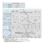
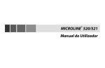
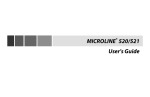
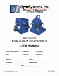
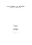
Condenser Specifications
XLC 85
CoolWare v7.1.1
Registered To: Johnson Controls - USA - Eric Ramon
Customer Name
End User Name
Project
Reference
Item
Data 11/9/2007
Atmospheric Pressure
Elevation
Condenser
14.70 psi
0 ft
OPERATING CONDITIONS
Refrigerant
Wet Bulb Temp
Condenser Temp
Condenser Pressure
R717 Actual Capacity
78.0 °F Catalog Capacity
95.0 °F
181.0 psig
844.3 mbh
1249.5 mbh
SPECIFICATIONS
Data
Airflow
No Fans
Fan Motor
Refrigerant Charge
Pan Heater
Pump Data
14600 cfm Spray
1 Motor
(1) 7.5 hp
91 lbm
kW
90.0 gpm
1.0 hp
Noise
Noise at 25 ft
Noise at 50 ft
Noise at 100 ft
Unit Weights
59.0 dBA Shipping
53.0 dBA Operating
47.0 dBA Heaviest Section
Dimensions
Height
Width
Length
Volume Required
3960 lbm
5070 lbm
3285 lbm
Remote Sump Data
106.9 in Water In
72.5 in Drain
117.0 in Volume Required
9.6 ft3
ERRORS AND WARNINGS
York Refrigeration - Frigid Coil
13711 Freeway Drive, Santa Fe Springs, CA 90670
Phone:(562)921-4310 Fax:(562)921-6412
York Refrigeration - Imeco
1590 Dutch Rd., Dixon, IL 61021
Phone(815)288-3859 Fax:(815)288-1665
Disclaimer: the information contained in this program is subject to change without notice. Frick reserves the right to final verification of all rating results.
2.5-MPT
4-FPT
95.0 gal
Form S140-600 IOM (NOV 2007)
INSTALLATION - OPERATION - MAINTENANCE
File:
Replaces:
Dist:
SERVICE MANUAL - Section 140
S140-600/NOV 2005
3, 3a, 3b, 3c
XL
EVAPORATIVE COOLING PRODUCTS
S140-600 IOM (NOV 07)
Page 2
XL EVAPORATIVE COOLING PRODUCTS
TABLE OF CONTENTS
NOTE: Installation, operation, maintenance, and repair of this equipment should only be accomplished by qualified personnel. Failure to follow this note may result in improper installation and operation of the equipment and personal injury.
Frick's XL Condensers are designed to ensure energy efficient operation and years of dependable, trouble-free service. To
maximize service life, it is important to follow the recommended installation, operation, and maintenance procedures outlined in
this manual. Be sure to follow the Recommended Maintenance Table and read the detailed instructions of each procedure. Care
taken to follow these instructions will directly affect the satisfactory operation and reliability of the system.
TABLE OF CONTENTS
Preface ................................................................................................................................ 3
Job Inspection...................................................................................................................... 3
Transit Damage Claims ........................................................................................................ 3
Unit Identification ................................................................................................................. 3
Safety Requirements ........................................................................................................... 3
Installation Tools .................................................................................................................. 4
General Information ............................................................................................................. 4
Installation Instructions ........................................................................................................ 5
Optional Vibration Isolator - Mounting Instructions .............................................................. 9
Final Assembly Details ...................................................................................................... 10
Operating Instructions........................................................................................................ 11
Maintenance Instructions ................................................................................................... 12
Water Treatment............................................................................................................. 12
Suggested Maintenance Intervals ................................................................................. 12
Fans ............................................................................................................................... 15
Operation and Maintenance .............................................................................................. 15
Operation and Maintenance Schedule .............................................................................. 16
Recommended Spare Parts .............................................................................................. 17
FIGURES
Figure 1a. XLC I-Beam Location.......................................................................................... 4
Figure 1b. XLP I-Beam Location .......................................................................................... 4
Figure 2. Platform Layout ..................................................................................................... 5
Figure 3a. XLC Pan Coil Section Rigging ............................................................................ 5
Figure 3b. XLC Fan Section Rigging .................................................................................... 5
Figure 4a. Mastic Placement For Blower Mounting ............................................................. 6
Figure 4b. Blower Assembly Mounting Instructions ............................................................. 6
Figure 5. XLC Unit Assembly with Desuperheater ............................................................... 6
Figure 6. Platform Layout ..................................................................................................... 7
Figure 7a. XLP Fan Section Rigging (All models except 1570-2 and 1660-2 — 1880-2) ............. 7
Figure 7b. XLP Fan Section Rigging (Models 1570-2 and 1660-2 — 1880-2) ............................ 7
Figure 7c. XLP Coil Section Rigging .................................................................................... 8
Figure 8. XLP Mastic Location and Unit Assembly .............................................................. 8
Figure 9. Vibration Isolator Feet ........................................................................................... 9
Figure 10. Vibration Isolator Rails ...................................................................................... 10
Figure 11. Eliminator .......................................................................................................... 10
Figure 12. XLC Spray Header Nozzle Orientation ............................................................. 13
Figure 13. XLP Spray Header Nozzle Orientation ............................................................. 13
Figure 14. Sheave Alignment ............................................................................................. 14
TABLES
Table 1. XLC Foundation Layout Dimensions ...................................................................... 5
Table 2. XLP Foundation Layout Dimensions ...................................................................... 7
Table 3. Rigging Cable Lengths ........................................................................................... 8
SAFETY PRECAUTION DEFINITIONS
NOTE:
Indicates an imminently hazardous situation which, if not avoided, will result in death
or serious injury.
Indicates a potentially hazardous situation or practice which, if not avoided, will result
in death or serious injury.
Indicates a potentially hazardous situation or practice which, if not avoided, will result
in damage to equipment and/or minor injury.
Indicates an operating procedure, practice, etc., or portion thereof which is essential to
highlight.
XL EVAPORATIVE COOLING PRODUCTS
GENERAL INFORMATION
PREFACE
S140-600 IOM (NOV 07)
Page 3
UNIT IDENTIFICATION
This manual has been prepared to advise the owner and service
personnel of recommended INSTALLATION, OPERATION,
AND MAINTENANCE procedures recommended by Frick
for XL Evaporative Cooling Equipment. Read the following
instructions completely prior to installation. These instructions
provide you with the information needed for safe, proper
installation, operation, and maintenance of your new product. Care taken during the installation will directly affect the
satisfactory operation and reliability of the system.
®
To ensure correct installation and application, the units must
be properly selected and connected to an appropriately
designed and installed system. The engineering plans, piping layouts, etc. must be detailed in accordance with the
best practices and local codes, such as those outlined in
ASHRAE literature.
All units should be rigged and installed as outlined in this
manual. These procedures should be thoroughly reviewed
prior to the actual rigging operation to acquaint all personnel
with the procedures to be followed. It is also important that
these units be applied to a properly controlled refrigeration
system. Your authorized Frick representative should be
consulted for expert guidance on questions pertaining to
installation and application.
If at any time during the review of this document or installation/operation you require assistance, please call your local
Sales representative.
JOB INSPECTION
PLEASE RECORD THE FOLLOWING INFORMATION FOR
FUTURE REFERENCE:
Model No.
Serial No.
Date Received
Immediately upon arrival at the job site, the unit should be
inspected to ensure all required parts have been received
and are free of shipping damage prior to signing the Bill of
Lading. Unpack all items and check against shipping lists for
any possible shortages. If any part appears to be missing,
contact your Frick representative. The following parts should
be inspected:
• Sheaves & Belts
• Bearings
• Bearing Supports
• Fan Motor(s)
• Fan(s) and Shaft(s)
• Coils
• Water Distribution
System(s)
• Spray Water Pump(s)
• Strainer(s)
• Float Valve Assembly(ies)
• Eliminators
• Interior and Exterior Surfaces
• Belt Guard(s)
• Motor Hood(s)
• Miscellaneous Items:
If required for field assembly, the following parts will be packaged and usually placed inside the pan section: Mastic, Bolts,
Nuts, Washers, and any accessory items.
TRANSIT DAMAGE CLAIMS
NOTE: When inquiring about the unit or ordering repair
parts, provide the MODEL and SERIAL NUMBERS from
the data plates.
SAFETY REQUIREMENTS
XL unit installation, operation, and maintenance – involves
heavy rotating machinery operating at high speed and high
voltage. Normal operations and maintenance procedures
may require working at elevations, enclosed space entry,
or use of hand and power tools. With these considerations,
safety must be the top priority in all activities with this evaporative cooling product.
Frick recommends that every client analyze and develop
an installation-specific safety regime that takes into account
such variables as specific site/system features, personnel
qualifications, hazard identification, etc. The following elements of operational safety are recommended for inclusion
in every client’s XL condenser safety plan/requirements:
Electric – Configure all power switches and controls to
provide an open, safe circuit before and during maintenance procedures, until the unit is cleared by management
for normal on-line operations. For extended shutdowns it is
recommended that a qualified technician remove fuses from
“fused-disconnect panels” or otherwise open the circuit in an
accepted, secure manner.
Fans – All fan covers, guards, and shaft retainers (if any)
must be in place before applying power to an XL condenser.
Always disengage and lock out power before allowing interior
inspections. To prevent foreign objects from being drawn
into rotating fan blades, never allow operation with hatch
off/open.
Enclosed space inspections – Inspections of condenser
coil, drift eliminators, etc., requires machinery lockout and
the use of a “lookout buddy” at a minimum. Consult your
internal safety policy and OSHA requirements for additional
safety rules/procedures.
All claims must be made by the consignee. This is an ICC
requirement. Request immediate inspection by the agent of
the carrier and be sure the proper forms are executed.
Vibration and noise – Discontinue or stop machinery that
emits unusual vibration and noise. The source must be
investigated (and apparent discrepancies corrected) before
testing or placing the unit back in operation.
Contact Parts and Warranty Department to report damage
or shortage claims.
Wet Surface Precautions – Poorly maintained/wetted
machinery requires care to avoid electrical shocks from in-
S140-600 IOM (NOV 07)
Page 4
XL EVAPORATIVE COOLING PRODUCTS
INSTALLATION
adequate/loose field wiring/connections. All personnel must
lock out and tag machinery before working on the condenser.
Proper safety precautions such as the use of insulating
soles/gloves and a trained “lookout buddy” are indispensable.
Ice formation in cold weather can present fall/slip hazards.
Icing safety procedures should be mandatory when the daily
ambient temperature falls below 40°F (4.4°C).
Each beam should be sized in accordance with standard
engineering practices, 55% of the operating weight of the
unit as a uniform load on the beam, allowing for a maximum
deflection of 1/360 of the length, not to exceed 1/2 inch.
Water Chemistry – All evaporative-cooled condensers operate on principles that encourage biological growth in the
recirculating water unless effective treatment is applied. Recirculating water must be periodically analyzed for biological
culture plate counts. XL units should not be operated without
an effective biological treatment program.
NOTE: Emergency “shock” treatment with chemical biocides may upset the unit’s appropriate pH range (creating
an excessively corrosive environment for the materials
of construction) and may expose operators to strong
chemicals that are corrosive or otherwise dangerous
if mishandled (see water treatment comments in the
CHEMICAL TREATMENT section of MAINTENANCE).
Field Piping Considerations for XL Unit Installation – All
IDC units require strongly supported and anchored field piping. No field piping is to be supported by the XL itself. Wind
loading, temperature variation, etc., must be considered to
allow for movement between the tower, building, optional
vibration isolator/rails, and field piping. A qualified cooling
system design engineer should provide final field-piping
plans and specifications.
Before finalizing piping installation plans, it is recommended
that related plans for cooling system/plant expansion be
discussed with your field piping/system designer and Imeco
sales representative. Incorporating pipe openings/sizes now
allows for easier installation in the future.
Figure 1a - XLC I-Beam Location On Unit
INSTALLATION TOOLS
To complete the installation of the XL Evaporative Condensers, the following tools are needed:
• Drift pins
• 8-foot straight edge
• Level
• Assorted open-end wrenches
• Socket set
• Belt tension gage
• Tape measure
GENERAL INFORMATION
All XLC and XLP models should be anchored directly to
concrete pads or concrete piers. These units may also be
supported on structural “I” beams as outlined below.
The Centrifugal Fan XLC units are designed to be supported by two structural “I” beams, one located under each
end of the unit and running the full width of the unit (See
Figure 1a).
The Vane Axial Fan XLP units are designed to be supported
by two structural “I” beams, one located under the front and
one under the rear of the unit, running the full length of the
unit (Figure 1b).
As an alternate, the structural “I” beams may run the full
width of the unit. Please refer to the unit foundation drawings
furnished by Frick for each specific sales order for complete
details.
Figure 1b - XLP I-Beam Location On Unit
XL EVAPORATIVE COOLING PRODUCTS
INSTALLATION
All units have 13/16 inch diameter mounting holes for mounting to the beams. The beams should be supported so that the
unit is level. Shims between the beams and the unit should
not be used, as this will not provide adequate support.
If vibration isolation is required, whether furnished by Frick or
by others, the isolators must always be mounted below the
structural “I” beams. Continuous support of unit, as described
above, must be provided.
S140-600 IOM (NOV 07)
Page 5
XLC CENTRIFUGAL FAN UNITS
XLC units are shipped in two pieces: the pan/coil section and
the fan section. The first step of the installation is to mount
the pan/coil section on the structural beams and bolt it to the
beams. The rigging of the two pieces is shown in Figures 3a
and 3b. For minimum cable length, see Table 1.
INSTALLATION
FOUNDATION LAYOUT INFORMATION FOR XLC UNITS
Beams and/or piers should be sized in accordance with
standard engineering practices, 55% of the operating weight
as a uniform load. Beam deflection should not exceed the
larger of 1/360 of span or 1/2 inch. In Figure 2, “A” represents the overall length of one cell and “B” represents the
center lines of the mounting holes in the unit. The dashed
lines show the location of the structural beams to which the
unit is mounted.
Table 1
XLC FOUNDATION LAYOUT DIMENSIONS
MODEL
XLC 25 through XLC 40
XLC 43 through XLC 55
XLC 58 through XLC 90
XLC 95 through XLC 128
XLC 130 through XLC 185
XLC 195 through XLC 250
XLC 285 through XLC 385
XLC 410-2
through XLC 500-2
XLC 570-2
through XLC 770-2
C
27.25
38.75
27.25
38.75
57.25
80.25
80.25
D
—
—
—
—
—
—
—
MIN.
CABLE
LENGTH
6 ft.
6 ft.
11 ft.
11 ft.
11 ft.
12 ft.
17 ft.
A
57
57
117
117
117
117
177
B
54
54
114
114
114
114
174
117
114 80.25 258
12 ft.
177
174 80.25 378
17 ft.
Figure 3a - XLC Pan/Coil Section Rigging
Figure 3b - XLC Fan Section Rigging
Figure 2 - Platform Layout
S140-600 IOM (NOV 07)
Page 6
XL EVAPORATIVE COOLING PRODUCTS
INSTALLATION
The second step of installation is to mount the fan section to
the pan/coil section as follows:
1. Remove guards from both ends and remove the vertical
guard between the blowers to provide access to mounting
holes. Also, remove the motor housing access panel.
2. Take mastic from parts box and place on coil section unit
body as shown in Figure 4a.
3. Lower fan section to pan/coil section unit body so that the
blower support on the fan section rests on the flanged edge
of the top fan mounting panel on the pan/coil section unit
body. Move the fan section to the pan/coil section unit body
until all mounting flanges are touching. (Figure 4b)
4. On each blower, install bolts with a flat washer under both
the bolt and nut.
5. Tighten all bolts connecting fan and pan/coil Sections
together before removing rigging.
6. Align the V-belt drive and check tension in the belts using
the procedures in the section labeled "Fan Drives and Belts"
in this manual.
Figure 4b - Blower Assembly Mounting Instructions
7. Replace all guards and the motor hood access panel.
NOTE: When provided, mount desuperheater on top of
unit using holes provided in the mounting bracket. Note
that some units are shipped with the desuperheater
factory mounted. Assemble gas piping between desuperheater and condensing coils after final positioning
of the desuperheater. Inter-gas piping is to be furnished
by others.
Figure 5 - XLC Unit Assembly With Desuperheater
Figure 4a - Mastic Placement For Blower Mounting
XL EVAPORATIVE COOLING PRODUCTS
INSTALLATION
FOUNDATION LAYOUT INFORMATION
FOR XLP UNITS
Beams and/or piers should be sized in accordance with
standard engineering practices, 55% of the operating
weight as a uniform load. Beam deflection should not
exceed 1/360 of span, or maximum of 1/2 inch. In Figure
6, “A” represents the overall length of one cell and “B”
represents the center lines of the mounting holes in the
unit. The dashed lines show the location of the structural
beams to which the unit is mounted.
S140-600 IOM (NOV 07)
Page 7
TABLE 2
XLP FOUNDATION LAYOUT DIMENSIONS
MODEL
S90 thru S175
S185,S190,S200,S205
S180, S195
S210 thru S270
M155 thru M280
M285 thru M430
M810-2 thru M960-2
ML235 thru ML345
L350 thru ML520
ML820-2 thru ML1040-2
L290 thru L415
L435 thru L700
L810-2 thru L830-2
L870-2 thru L1400-2
XL355 thru XL530
XL535 thru XL805
XL785, 830 – 940
XL830-2 thru XL1060-2
XL1070-2 thru XL1650-2
XL1570-2 and
XL1660-2 thru XL1880-2
A
B
C
D
145
141
57.5
—
145
141
68.5
—
92
92
92
92
92
92
112
112
112
112
137
137
137
137
137
—
—
378
—
—
446
—
—
314
446
—
—
—
314
446
137
514
121.87 117.87
177
173
177
173
145
141
211
207
211
207
145
141
211
207
145
141
211
207
145
141
211
207
245
241
145
141
211
207
245
241
E
F
1.625
0.75
2.125
2
Figure 6 - Platform Layout
INSTALLING XLP SINGLE LENGTH UNIT
XLP units are shipped in two pieces, the pan/fan section and
the coil section. The first step of the installation is to mount
the fan/pan section on the structural beams with bolts. The
rigging of the two pieces is shown in Figures 7a through 7c.
For cable lengths, see Table 3.
Figure 7a - XLP Fan Section Rigging (All models
except 1570-2 and 1660-2 through 1880-2)
Figure 7b - XLP Fan Section Rigging (Models 1570-2
and 1660-2 through 1880-2)
S140-600 IOM (NOV 07)
Page 8
XL EVAPORATIVE COOLING PRODUCTS
INSTALLATION
Table 3
RIGGING CABLE LENGTHS
XLP
Model
Figure 7c - XLP Coil Section Rigging
The second step of the installation is to mount the coil section as follows:
1. Some units are shipped with the fan guards in the pan
section for shipping purposes. In these cases, remove fan
guards from pan section and install on the front of the unit
before joining fan and coil sections.
Min. Cable Length
S
14 ft
M - 2 Fan
13 ft
M - 3 Fan
17 ft
ML - 2 Fan
15 ft
ML - 3 Fan
20 ft
L - 2 Fan
16 ft
L - 3 Fan
21 ft
XL - 2 Fan
17 ft
XL - 3 Fan
22 ft
4. Remove rigging and install four 1/2" bolts with flat washers
under both the bolt and nut.
NOTES:
1. Use spreaders and blocking to protect casing from
possible damage caused by slings.
2. Remove eliminator tie straps and eliminators as necessary to access lifters.
2. Take mastic from parts box and place on the top of the
fan & pan section as shown in Figure 8. Be sure to apply two
layers of mastic across each end of the unit as shown.
3. Mount coil connection toward access door unless
specified differently on product drawing.
3. Lower the coil section to the fan & pan section with rigging
attached to all eight lifters. For extended lifts, use lifters and
safety slings (Figure 7c). Use drift pins in bolt holes to ensure
proper alignment. See Figure 8.
4. When provided, mount desuperheater on top of unit
using the holes provided in the mounting bracket. Assemble piping between desuperheater and coil after final
positioning of desuperheater.
Figure 8 - XLP Mastic Location And Unit Assembly
XL EVAPORATIVE COOLING PRODUCTS
INSTALLATION
S140-600 IOM (NOV 07)
Page 9
OPTIONAL VIBRATION ISOLATOR
MOUNTING INSTRUCTIONS
Vibration isolators, purchased as an option, are used to
minimize transfer of forces due to vibration/dynamic loading to or from unit. To install the isolator feet and rails, refer
to Figure 9 and Figure 10 respectively and follow these
instructions:
ISOLATOR FEET
1. Refer to the submitted foundation layout drawing for the
correct location of each isolator and support beams.
2. Place the isolators in their proper location and attach the
bottom plate to the building support steel by means of bolting or welding.
3. Set the unit support beams on top of the isolators and attach them to the top plate by means of bolting or welding.
Figure 9 - Vibration Isolator Feet
4. Lower the first section of the unit onto the beams, taking
care not to overload any one corner.
ISOLATOR RAILS
Do not attempt to move the unit
laterally with the weight on the
isolators. If it is necessary to move
the unit, remove the weight from the isolators by raising
the unit before moving. Failure to follow this procedure
could result in damage to the isolator.
5. Attach the unit to the beam by means of bolting or
welding.
6. Continue to attach the remaining unit sections per the
instructions on the previous pages and complete piping,
wiring,etc.
NOTE: Ridged connections between the unit and building
structure shall not be permitted when vibration isolators
are used. Use flexible connections that allow for vibration
and noise isolation.
7. Loosen the vertical restraint jam nuts to the end of the
restraint bolts.
8. When the unit is completely installed and operating, turn
the leveling bolts counterclockwise several complete turns
on each isolator until the blocking channel can be removed
by hand. It will be necessary to alternate between isolators
in order to uniformly raise the unit. Do not attempt to place
all the weight on any one isolator, but distribute the load
proportionally.
9. After the unit is level, tighten the vertical restraining nuts
finger tight, then back off one half turn. Lock each nut with
the jam nuts provided.
1. Refer to the submitted foundation layout drawing for the
correct location of each isolator rail.
2. Place the isolator rail assemblies in their proper location
and attach the bottom plate to the building support steel by
means of bolting or welding.
3. Lower the first section of the unit onto the rails, taking care
not to overload any one corner.
Do not attempt to move the unit
laterally with the weight on the
isolators. If it is necessary to move
the unit, remove the weight from the isolators by raising
the unit before moving. Failure to follow this procedure
could result in damage to the isolator.
4. Attach the unit to the isolator rail by means of bolting or
welding.
5. Continue to attach the remaining unit sections per the
instructions on the following pages and complete piping,
wiring, etc.
NOTE: Ridged connections between the unit and building structure shall not be permitted when vibration
isolators are used. Use flexible connections that allow
for vibration and noise isolation.
6. Temporarily remove all vertical locknuts from hold-down
bolt.
7. When the unit is completely installed and operating, turn
the leveling nuts clockwise several complete turns on each
isolator until the shim can be removed by hand. It will be
necessary to alternate on each isolator in order to uniformly
raise the unit. Do not attempt to place all the weight on any
one isolator, but distribute the load proportionally.
8. After the unit is level, replace all vertical locknuts on holddown bolts and fasten finger tight.
S140-600 IOM (NOV 07)
Page 10
XL EVAPORATIVE COOLING PRODUCTS
INSTALLATION
Figure 10 - Vibration Isolator Rails
FINAL ASSEMBLY DETAILS
1. ELIMINATOR PLACEMENT
Check the placement of the eliminator sections on the top
of the unit to ensure that all eliminator sections are properly
interlocked and that there are no openings present which
will allow the escape of water droplets. Eliminator tie-down
straps can be removed after assembly is complete. Check
the orientation of the eliminator sections to ensure "RIGHT
SIDE UP" as shown in Figure 11.
J. Check fans and pumps for correct rotation and electrical
hook-up.
K. See the Operation and Maintenance Manual for new belt
run-in procedures.
3. BREAKING IN THE GALVANIZED SURFACES
A proper break-in procedure should be followed for water
treatment to allow the galvanized surfaces to break in or
passivate. This allows the galvanized surfaces to form a
self-protecting zinc carbonate layer. A qualified water treatment specialist can provide specific details, but following are
some guidelines.
• Clean all wetted surfaces.
• Touch up scratches in the galvanizing with cold galvanized paint.
Figure 11 - Eliminator
• Keep the water as close neutral (pH 7.0) as possible.
Must be between 6.5 and 7.5 at all times during the
break-in period.
2. INSPECTION
• Avoid cleaning chemicals in pH ranges above 8.0 and
below 6.0.
Prior to start-up, the following services, which are described
in detail in the operating and maintenance manual, must be
performed:
• Operate under minimal load during the break-in period.
When the unit is installed, the water can be circulated
through the unit before the refrigerant piping is connected to begin the passivation process.
A. Inspect general condition of unit.
B. Inspect fan, motors, bearings, drives, and locking collars
for condition and alignment.
C. Check belt tension and condition per the maintenance
manual instructions.
D. Lubricate all bearings.
E. Inspect spray headers and heat transfer section.
F. Check makeup valve and sump water level.
G. Check fans and guards for obstructions.
H. Clean and flush pan and strainer.
I. Rotate fan(s) by hand to ensure rotation without
obstruction.
• After the break-in period, typically 30-45 days, begin
regular water treatment procedures.
Again, local water treatment professionals will be best
equipped to create a water treatment program designed to
meet the specific needs of the installation.
Proper start-up procedures and scheduled periodic maintenance will prolong the life of the equipment and ensure
trouble-free performance for which the unit is designed.
DO NOT ATTEMPT ANY INSPECTION AND/OR MAINTENANCE
UNLESS THE ELECTRICAL SUPPLY HAS BEEN COMPLETELY DISCONNECTED AND
LOCKED OUT.
XL EVAPORATIVE COOLING PRODUCTS
OPERATION
OPERATION
S140-600 IOM (NOV 07)
Page 11
COLD WEATHER OPERATION
Frick Evaporative Condensers are suitable for most cold
weather applications when supplied with proper capacity
control and freeze protection.
®
Frick Evaporative Condensers remove heat from the fluid
circulating in the coil by recirculating water over the outside of
the coil and blowing air up through the wetted coil. The water
that is recirculated over the outside of the coil is stored in the
pan section at the bottom of the unit, and is pumped over the
coil through spray nozzles by the spray pump mounted on the
end of the unit. The fans are located on the side of the XLC
Centrifugal Fan Units in the dry entering air stream and are
driven by a motor that is mounted on top of the fan section.
The fans on the XLP Vane Axial Fan Units are located above
the pan in the pan/fan section in the dry entering air stream
and are driven by motors that are located below the fans.
®
A common application for Vane Axial units is to cycle the
operating fans to achieve capacity control. Typically, the fans
are cycled off as capacity drops and finally, the pump is shut
off. In cold weather operation, Frick recommends that the
pump should be the first item shut off to achieve capacity
control. By running the unit dry in cold applications, the unit’s
drive is protected from ice formation. Ice forms when the spray
water causes moist air to migrate out of idle fans where it
condenses and freezes on cold metal surfaces.
®
The coolers are designed to provide maximum capacity when
both the spray system and the fans are running, and only
partial capacity when either the spray system or the fans are
running alone. A practical method of capacity control is to
cycle the fan and spray pump motors with a thermostat or
pressure switch that senses the fluid leaving the unit. Care
must be taken, however, to cycle the fans off first, then the
spray pump. This enables the solids left behind to be washed
into the pan, by the spray water, where they can be bled off
to the drain.
As long as the Evaporative Condensers are in operation
with a load, with capacity control dampers, the recirculating
pan water will not freeze. However, the pan water must be
protected when Evaporative Condensers are under a “no
load” condition with fans and spray pumps off. An indoor
remote sump and pump is the best means of avoiding pan
water freezing in an idle Evaporative Condenser. With this
remote sump system, the pan water is always drained to
the indoor remote sump whenever the recirculating water
pump is stopped.
When provided, capacity control dampers are mounted
in the discharge throat of the fans on the XLC units or on
the air discharge of the XLP units for closer control of fluid
temperature or pressure. These dampers are controlled
by a modulating damper actuator and a remote bulb-type
temperature or pressure controller. The sensing bulb of the
controller should be installed in the fluid piping leaving the
unit, and the controller should be wired to the damper actuator as shown on the appropriate wiring diagram. The damper
actuator contains an end switch that should be used to turn
off the fan motor when the dampers are fully closed.
Because of the Evaporative Condenser location or space
limitations, a remote sump installation may be impractical.
In such cases, supplementary heat must be supplied to the
pan water. The Evaporative Condenser will then need to be
furnished with an electric pan heater. This heater will provide
sufficient heat to keep the spray water in the pan from freezing when the unit is not running. The heater is controlled by
a thermostat that senses the pan water temperature, and is
factory set at 42°F. The heater is protected by a low water
cutout switch that prevents the heater from operating if the
pan water level is below the heater element. In addition to protecting the pan water, all exposed water piping, including the
pump suction line, pump, pump discharge piping (up to the
overflow connection), and the make-up water lines, should be
traced with electrical heat tape and insulated. Some Evaporative Condenser installations will permit all spray water to
be drained from the pan during cold weather operation. This
permits dry operation of the Evaporative Cooler or Condenser
when the load and ambient temperatures are low.
Units provided with positive closure discharge dampers are
designed to reduce heat loss from the unit when it is not in
operation by eliminating the chimney effect. The dampers are
operated by an “On-Off” damper actuator, and are positioned
closed when the spray pump motor is off, and open when
the spray pump motor is on. The actuator should be wired
as shown on the appropriate wiring diagram.
Units that require year-round operation in a freezing climate
should be equipped with an electric pan water level control
package. This package ensures a constant water level without adjustment and also maintains very close control of the
pan water level. The system consists of a weather-protected
electric float switch with stilling chamber mounted on the pan
section and a weather-protected solenoid valve mounted on
the water makeup connection. When this system is used, it
replaces the standard mechanical water makeup valve.
S140-600 IOM (NOV 07)
Page 12
XL EVAPORATIVE COOLING PRODUCTS
MAINTENANCE
MAINTENANCE
Frick Evaporative Condensers accomplish condensing by
evaporating water from the spray water system at the rate
of two gallons per minute per one million BTU’s per hour of
heat removed, or three GPM per 100 tons of refrigeration.
When this water evaporates, however, the solid impurities
remain and must be flushed from the system to prevent a
scale build up on the coil and casing. This is accomplished
by a bleed-off valve located on the spray pump discharge
line which bleeds off an equal amount of water to that which
is evaporated.
chemical concentration of the water outside of the acceptable ranges listed above.
®
For conditions where the original water hardness is very
high or a large number of airborne contaminants may
enter the spray water, a higher bleed-off rate or chemical
treatment may be required to prevent scale buildup on
the coil. Consult your local water treatment company for
recommendations.
WATER TREATMENT
If the condition of the water is such that constant bleed-off
will not control scale and/or control the recirculating water
pH level within the acceptable range listed below, chemical
treatment may be required. If a water treatment program
is to be used, please consult a competent water treatment
specialist, but use the following guideline as a minimum
requirement:
• Chemicals must be compatible with zinc galvanic protection
and maintained in proper concentration to be compatible
with all materials of construction.
• The circulating water must be maintained between 6.5 and
8.0 pH at all times. Below 6.5, corrosion and/or accelerated
consumption of protective zinc material will occur. When
the pH reaches 8.3 or above, white rust may occur which
will require passivation as discussed below.
• Maintain total dissolved solids below 1000 parts per million.
• Maintain alkalinity hardness between 100-300 parts per
million.
• Maintain chlorides below 200 parts per million.
• Maintain sulfates below 250 parts per million.
• Chemicals should be fed into the recirculated water, but not
into the cold water sump, on a continuous metered basis
to avoid localized high concentrations which may cause
corrosion. Batch feeding of chemicals does not provide
adequate control of water quality and may lead to harmful
concentration levels. Batch feeding is not recommended.
• Acid water treatment may be used but requires additional
controls and significant caution. Acids are very harmful
to galvanized surfaces, so the resulting pH levels must
be closely monitored. Unfortunately, some water supplies
provide highly alkaline water that can lead to white rust
and must be tempered to more moderate pH levels. When
acid treatment is required, sufficient feed controls must be
put into place to maintain the pH of the water that comes
into contact with the condenser components (coil, walls,
sump, etc) within the aforementioned acceptable range. It
is recommended that the chemical feed for acid treatment
be done in a tank, such as a remote sump tank, that allows
complete diffusion of the chemical before it is pumped to
the unit. In addition to the chemical feed controls, regular
inspections of feed valve and chemical levels should be
included in the preventative maintenance plan to avoid
• The unit interior including the condenser walls above
and below the coil, the coil and the sump basin should
be inspected regularly. Signs of corrosion or excessive
scale will highlight problems in the water treatment system.
These must be addressed quickly to prevent significant
damage to the protective galvanized surface.
• The use of simple bleed-off or chemical treatment for
control of scale or corrosion does not preclude the need
to control biological contamination. Treatment with biocide
is a necessary part of required water treatment.
Upon initial commissioning of the equipment, passivation
of the galvanized surfaces is required. As discussed above,
when the pH levels are elevated during normal operation,
the passivation process discussed below will be required.
Passivation allows a galvanized surface to develop its protective layer of zinc carbonate and is an important part of
the water treatment process. During passivation, operate the
condenser as follows:
• Clean all surfaces.
• Maintain pH levels as close to 7.0 as possible. Do not allow
the pH to fall below 6.5 or to rise above 7.5 at any time
during passivation.
• Phosphate treatments can assist in the passivation
process.
• Operate under minimal load. When the unit is installed,
the water can be recirculated through the unit before
refrigerant piping is connected to begin the passivation
process.
• Maintain these conditions for a period of 30-45 days.
• NOTE: if start-up does not allow for minimal load
conditions for the required duration, the passivation
can be repeated during the fall or winter following
start-up.
The following paragraphs contain specific and critical maintenance operations required for the components that make
up the water circulation system.
SUGGESTED MAINTENANCE INTERVALS
BLEED-OFF VALVE
The bleed-off valve should be checked monthly to ensure
that it is not blocked and that water is flowing as required.
The valve should be set so that the bleed-off rate is two GPM
per one million BTU’s/hour of heat removed (or per 83 tons of
refrigeration). The bleed valve should always be open, unless
the unit is controlled by a water treatmen t system.
STRAINER
The pan water strainer is located at the bottom of the pan
section at the suction connection of the spray pump. The
strainer should be cleaned monthly, or as conditions require,
to keep it clean. The strainer is easily accessible through
the access door. Do not operate the unit without the
strainer.
MAKEUP VALVE
The pan water level is controlled by a float-actuated valve that
is accessible through the access door. This valve should be
checked monthly for proper operation and water level. The
XL EVAPORATIVE COOLING PRODUCTS
MAINTENANCE
pan water level should be even with the centerline of the
overflow when the unit is not running. This will prevent the
pump from cavitating when the spray system is in operation.
The water level is easily adjusted by loosening the wing nut
on the valve and raising or lowering the ball to maintain the
proper level. The recommended operating pressure for the
water makeup valve is 15 to 20 PSI.
MOISTURE ELIMINATORS
The moisture eliminators are located on top of the unit and
prevent losses of the spray water due to water being entrained
in the air stream as it passes through the unit. The eliminators
should be checked monthly to remove any obstructions that
may be trapped between the blades and to ensure proper
positioning.
WATER DISTRIBUTION SYSTEM
The spray nozzles are accessible by moving the eliminators
in sections from the top of the unit (DO NOT OPERATE UNIT
WITHOUT ELIMINATORS). The spray nozzles are large
orifice, cleanable type. For XLC units, the nozzles should be
checked monthly to see that the spray pattern is complete
and even. Figure 12 shows the nozzle orientation in the spray
headers and the spray direction.
Figure 12 - XLC Spray Header Nozzle Orientation
S140-600 IOM (NOV 07)
Page 13
competitive nozzles. There is adequate space below the
nozzle and a wide opening to allow large debris to be pulled
out. Furthermore, with the fixed design, this nozzle is much
more tolerant of harsh water conditions that lead to wear on
moving nozzles
NOTE: If the nozzle is removed for cleaning, always
ensure that the initial orientation of the nozzle is maintained. See Figure 13.
HEAT TRANSFER SECTION
The coil should be examined monthly for signs of scale
buildup, and any obstructions between the tubes should be
removed. If there is evidence of scale buildup on the coil,
check the bleed valve for adequate bleed-off. If the bleed-off
valve is functioning properly, contact your local water treatment company for recommendations.
FAN MOTOR AND SPRAY PUMP MOTOR
The motors should be checked and/or lubricated every six
months according to the motor manufacturers recommendations.
FAN BEARINGS
The fan bearings should be checked monthly and relubricated. The bearings should be lubricated while in operation,
and the grease should be pumped in slowly until a slight
bead forms around the seals. The grease will increase in
temperature approximately 30°F during the relubrication. If
the relubrication must be done while the bearings are not
in operation, the grease capacity of each bearing on the
XLC units is 7/8 ounce. The capacity on the XLP units is
3/8 ounce. The grease should conform to NLGI Grade Two
consistency and should be free of any chemical impurities
such as free acid or free alkali, dust, rust, metal particles
or abrasives. Bearings should be lubricated with hand
grease guns only.
The following types of grease meet the above criteria:
MOBILITH 22
MOBILUX #2
SHELL ALVANIA #2
UNIREX N2
TEXACO MULTIFAX #2
TEXACO PREMIUM RB
FAN DRIVE AND BELTS
The fan and motor sheaves and belt tension should be
checked every month using the procedure outlined below.
The sheaves should be tight on the shafts and should be
aligned properly to minimize belt wear. The belts should
be checked for wear along the edges as any irregularity
will cause vibration. If the belts are not wearing evenly, the
cause could be improper sheave alignment. Use the sheave
alignment procedure below to check the sheave alignment.
If any belt requires replacement, replace all the belts with a
matched set, never one at a time.
Figure 13 - XLP Spray Header Nozzle Orientation
SHEAVE INSPECTION
XLP units include low pressure, large orifice, clog-resistant
nozzles. They features a large 2" connection that provides
consistent, highly uniform water flow over a 6' square area
of the coil bundle for maximum heat transfer.
Check the sheaves for proper alignment, excessive corrosion, and wear or damage. Also, check the belt for excessive
heat. If the belt is too hot to touch, then the sheaves may be
damaged or need aligning.
The large nozzle opening avoids the pitfalls of most other
nozzles because most materials will pass straight through,
avoiding much of the maintenance required by smaller,
If the sheaves have excessive corrosion or are worn or damaged, they should be replaced. Check for sharp edges from
wear or pitting of the grooves from corrosion. Either condition
S140-600 IOM (NOV 07)
Page 14
XL EVAPORATIVE COOLING PRODUCTS
MAINTENANCE
will promote belt wear and increase turnover. Groove gauges
are also available to make it easy to see if the grooves are
worn. If more than 1/32” of wear can be seen, the sheave
should be replaced.
Alignment of sheaves is extremely important for proper belt
installation. The sheaves are aligned at the factory, but should
be rechecked when new belts are installed. Use a straight
edge to check alignment. Misalignment will show up as a gap
between the outside face and the straight edge. Two conditions for misalignment exist, angular and parallel. To check
both parallel and angular alignment, refer to the Figure 14
below and follow these instructions:
1. While placing a straight edge across the top of both motor
and fan sheaves, check for four points of contact.
2. If a four-point contact is achieved, skip to the belt tensioning section.
3. To adjust for parallel misalignment, adjust the motor or
fan shaft sheave.
4. To adjust for angular misalignment, adjust the motor mount
adjustment nuts. This should also be done when tensioning
the belt.
3. Move the motor until there is enough slack in the belt so
it can be removed without prying.
4. Remove the old belts and inspect for unusual wear. Excessive wear may indicate problems with alignment or sheave
damage.
5. Order replacement belts from the factory to ensure a
proper belt equivalent.
6. Inspect other drive components such as bearings and
sheaves for alignment, wear, lubrication, etc.
7. Clean the sheaves of debris before installing the new
belt.
8. Install the new belts, align the drive, and tension the belts
according to the procedures outlined here.
Belt Tensioning
Proper tension of a belt is very important to ensure maximum
belt life. If too little tension is applied, the belt will slip. Too
much tension can reduce belt and bearing life. It is not recommended that belt dressing is used when belt slippage occurs
as this will damage the belt and cause premature failure.
1. Decrease the center distance between the sheaves so
that the sheaves are somewhat loose.
2. Arrange the belts so the top and bottom spans have the
same amount of sag. On vertical drives, arrange the belts so
that each side has about the same amount of slack.
3. Apply tension to the belts by increasing the center distance
between the sheaves until the belts are snug.
4. Operate the drive a few minutes to seat the belts in the
sheave grooves. Observe the operation of the drive during
start-up. A slight bowing of the slack side of the drive indicates proper tension. If the slack side remains taut during the
peak load, the drive is to tight. Excessive bowing or slippage
indicates insufficient tension. If the belts squeal as the motor
comes on, they are not tight enough. The drive should be
stopped and the belts tightened.
NOTE: Do not overtighten the drive. If the above procedure
still results in the belts squealing, but the belts are still taut
on the slack side, a more precise method of testing the belt
tension must be used. In this case, use a belt tensioning gage
available from V-belt drive manufacturers or from factory.
New Belt Run-In
During initial startup of new belts, a belt run-in procedure is
recommended. During start-up, follow these instructions:
1. During start-up, look and listen for unusual noise or vibration.
Figure 14 - Sheave Alignment
Belt Replacement
When the decision is made to replace the belt, follow these
steps:
1. Lock and tag out the starter.
2. After the power has been turned off and the motor guard
removed, loosen the motor mount adjustment nuts.
2. After shutting down and locking out the starter, check the
bearings and motor. If they feel hot, the belt tension may be
too tight.
3. Run the drive under full load for 24 hours of continuous
operation. Running the belts under full load allows them to
seat themselves into the grooves.
4. After running the drive, check the tension of the belts.
Retension to the recommended values.
This run-in procedure will reduce the future need for re-tensioning and will help extend the life of the belts.
XL EVAPORATIVE COOLING PRODUCTS
MAINTENANCE
FANS
The fans should be checked monthly for any debris caught
in the blades. Any foreign material that has accumulated between the blades should be removed to prevent air capacity
reduction or an imbalance, resulting in excessive vibration.
CASING FINISH
The casing finish should be checked annually for corrosion
that may have occurred due to the alternating wet and dry
conditions. Any area that has corroded should be thoroughly
cleaned and retouched with a zinc-rich compound.
DISCHARGE CLOSURE DAMPERS/CAPACITY
CONTROL DAMPERS/LINKAGES
Under normal operating conditions, all bearings and other
working joints must be lubricated every three months with a
water-resistant grease which is rated for satisfactory performance at an ambient temperature range of -65°F to 250°F.
All linkages should also be inspected monthly to ensure
proper adjustment and flexibility. All linkage ball joints should
be lubricated every three months with the same grease
mentioned above.
ELECTRIC PAN WATER LEVEL CONTROL PACKAGES
Inspect Stilling Chamber for obstructions every three
months.
OPERATION AND MAINTENANCE
INITIAL AND SEASONAL START-UP
Before initial start-up or after a long shutdown period, the unit
should be thoroughly inspected and cleaned. The start-up
sequence should be:
1. Clean any debris from guards, fans, eliminators, heat
transfer sections, and cold water sump.
2. Flush the cold water sump (with strainers in place) and
drain to remove accumulated dirt.
3. Remove, clean, and replace sump strainers.
4. Turn the fan(s) by hand to ensure rotation without
obstruction.
5. Check and, if necessary, adjust the fan belt tension.
6. Prior to seasonal start-up, lubricate the fan shaft and motor
bearings. The ball bearings are factory lubricated, but should
be relubricated if the unit has been sitting on site for more
than a year before start-up.
7. On units furnished with discharge closure dampers and/or
capacity control dampers, lubricate all bearings and other
working joints and ensure proper linkage operation.
8. Check float-operated makeup valve to be sure it is operating freely.
9. Fill cold water sump with fresh water to the overflow
level.
10. Adjust the float on the makeup valve to shut off the
valve when the float is approximately 1.0" to 1.5" below the
centerline of the overflow.
11. Start spray pump and check for the proper rotation as
indicated by sticker on pump motor. On “Remote” installations
where the unit pump was not furnished by the factory, a globe
S140-600 IOM (NOV 07)
Page 15
valve should be installed in the pump discharge line and the
pump flow rate adjusted to the correct water flow.
12. Inspect spray nozzles and heat transfer section.
13. Check the locking collar on each fan shaft bearing and
tighten if necessary.
14. Start the fan(s) and check for proper rotation as indicated
by sticker on unit.
15. Check the voltage and current of all three legs of the fan
and pump motors. The current should not exceed the rated
service factor. After prolonged shutdowns, the motor insulation should be checked with a Megger Insulation Tester prior
to restarting the motors.
16. Open the bleed line valve and adjust bleed to the recommended rate.
17. On units furnished with electric water level control packages, ensure that the stilling chamber is free of obstructions.
AFTER 24 HOURS
After 24 hours of operation under load, the following services
should be performed:
1. Check unit for any unusual noise or vibration.
2. Check the operating water level in the cold water sump.
Adjust if necessary.
3. Readjust fan belt tension if required.
4. Inspect spray nozzles and heat transfer section.
OPERATION
During operation, the unit should be inspected, cleaned and
lubricated on a regular basis. The required services and
recommended frequency for each are summarized in the
Operation and Maintenance Schedule in this manual.
SEASONAL SHUTDOWN
The following services should be performed when the unit is
to be shutdown for a prolonged period:
1. Drain the cold water sump and all piping that will be exposed to freezing temperatures.
2. Clean and flush the cold water sump with sump strainer
in place. Leave the drain open so rain and melting snow will
drain from the unit.
3. Clean the sump strainers and reinstall.
4. Lubricate the fan shaft and motor bearings, motor base
and motor base adjusting screws.
5. Close shut-off valve in water make-up line and drain all
exposed make-up piping.
6. Inspect the protective finish on the unit. Clean and refinish
as required.
7. On units furnished with discharge closure dampers and/or
capacity control dampers, lubricate all bearings and other
working joints.
8. On units equipped with electric water level control packages, inspect stilling chamber to ensure it is free of any
obstructions.
S140-600 IOM (NOV 07)
Page 16
XL EVAPORATIVE COOLING PRODUCTS
MAINTENANCE
OPERATION AND MAINTENANCE SCHEDULE
TYPE OF SERVICE
Inspect General Condition of Unit
Clean debris from unit
Clean and flush sump
Clean sump strainer
Check and adjust sump water level
Inspect heat transfer section
Inspect spray nozzles
Check and adjust fan belt tension
Check and adjust bleed rate
Check operation of make-up valve
Check unit for unusual noise or vibration
Check fan bearing locking collars
Check motor voltage current
Lubricate fan shaft bearings
Lubricate motor base adjusting screws
Lubricate the fan and pump motors
Check fan for rotation without obstruction
Check fan and pump motor for proper rotation
Drain sump and piping
Inspect protective finish
Lubricate capacity control and/or discharge
closure damper bearings and working joints
Inspect/adjust damper linkage
Inspect electric pan water level control
"stilling chamber"
START-UP
MONTHLY
X
X
X
X
X
X
X
X
X
X
X
X
X
X
X
X
X
X
X
X
X
X
X
X
X
X
X
X
X
EVERY 6
MONTHS SHUTDOWN
ANNUALLY
X
X
X
X
X
X
X
X
X
X
X
EVERY 3
MONTHS
X
X
X
X
X
X
X
X
X
X
X
Before performing any maintenance or inspection, make certain that all power has been
disconnected.
SAFETY
FREEZE PROTECTION
Adequate precautions should be taken to safeguard the
equipment and the premises from damage and the public
from possible injury as appropriate for the installation and
location of these products.
These products must be protected against damage and/or
reduced effectiveness due to possible freeze-up by mechanical and operating methods. Please refer to the Cold Weather
Operation guidelines
XL EVAPORATIVE COOLING PRODUCTS
MAINTENANCE
S140-600 IOM (NOV 07)
Page 17
SPARE PARTS
Frick recommends that the customer maintain the following spare parts “in stock” for the Evaporative Condenser. By maintaining
this inventory of spare parts, continuous unit operation will be ensured.
®
Contact your local Frick representative for pricing.
The type and recommended stock level for each part is listed below.
MODEL
SERIAL NUMBER
PART NUMBER
RECOMMENDED STOCK LEVEL
*FAN BELTS - __________________________________________________
One Set
*FAN BEARINGS - _______________________________________________
One Set
FAN BUSHING - ________________________________________________
One Set
MOTOR BUSHING - _____________________________________________
One Set
FAN SHEAVE - _________________________________________________
One Set
MOTOR SHEAVE - ______________________________________________
One Set
FLOAT VALVE ASSEMBLY - _______________________________________
One
SPRAY NOZZLES - ______________________________________________
One Set
*FAN MOTOR - _________________________________________________
One Set
*SPRAY PUMP - ________________________________________________
One
FAN SHAFT - ___________________________________________________
One
* Parts noted to be considered as critical components to be stocked by customers to ensure continuous unit operation.