1
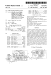
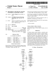
US006065296A
United States Patent [19]
[11]
Feger
[45] Date of Patent:
[54]
[75]
6,065,296
May 23, 2000
Heap Pump Service Manual, Model CDHP—35 Publication
SINGLE PACKAGE VERTICAL AIR
CONDITIONING SYSTEM
Mar. 22, 1990.
Inventor: Gary K. Feger, San Antonio, Tex.
Sales brochure for CDHP Series.
[73] Assignee: U.S. Natural Resources, Inc., San
Antonio, TeX.
Greg A. MaZurkieWicZ, “Insider Heat Pump Gets Inside
Track on Manufactured Hones,” Air Conditioning, Heating
and Refrigetation News, Apr. 7, 1997, p. 29.
Marvair, SiXpac Air Conditioner Sales Brochure.
[21] Appl. No.: 09/144,224
[22] Filed:
Aug. 31, 1998
WeatherWafer, Air Conditioners and Heat Pumps Sales
Brochure.
[51]
Int. Cl.7 .................................................... .. F25B 45/00
[52]
US. Cl. .............................. .. 62/77; 62/259.1; 62/298;
62/150; 62/280; 62/291; 62/285; 62/97;
62/404
[58]
Patent Number:
Field of Search .................................. .. 62/2591, 298,
62/150, 280, 291, 285, 97, 404, 77
Installation and Maintenance Instructions PWC Series, Self
—Contained Heat Pump.
Carrier 50 CP/QP Master Price List.
Retroaire, Installation Operation and Maintenance Manual.
Tri—Pac, CPH Series, Compact Water Heater Sales Bro
[56]
References Cited
chure.
U.S. PATENT DOCUMENTS
4,449,376
5/1984 Draper et al. ........................ .. 62/259.1
Primary Examiner—Henry Bennett
4,462,460
7/1984
Assistant Examiner—Mark Shulman
Braver ..................................... .. 165/26
5,034,033
7/1991 Alsup, Jr. et al. .
5,140,830
8/1992 Sawyer .................................... .. 62/298
5,271,242 12/1993 Addington
Attorney, Agent, or Firm—Gunn, Lee & Keeling
[57]
ABSTRACT
5,284,027
2/1994 Martin, Sr.
5,619,864
4/1997 Reedy ..................................... .. 62/428
This disclosure features a single package vertical air condi
5,622,058
4/1997 Ramakrishnan et al. .
tioner (both evaporator and condenser) in an easily installed
5,638,695
6/1997 Kamio et al. ........................... .. 62/279
cabinet. The cabinet includes a chassis above a dual level
drain pan having a sump. The pan sits on a set of rubber feet
OTHER PUBLICATIONS
to enable mounting. Side openings align With a telescoping
Heat Pump Service Manual, Models: CDHP18, CDHP24,
tWo part plenum to connect to a louvered grill on the outside
CDHP 30 Published Dec. 3, 1990.
Heat Pump Installation Manual, Models: CDHP18,
CDHP24, CDHP30, DHP35; Publication Dec. 3, 1990.
of a building to enable fresh air input and heat exchange.
26 Claims, 6 Drawing Sheets
U.S. Patent
May 23, 2000
Sheet 1 0f 6
6,065,296
U.S. Patent
kg
14
May 23, 2000
Sheet 2 0f 6
6,065,296
U.S. Patent
May 23, 2000
Sheet 3 0f 6
6,065,296
3
T
4/“)\ )I\Q
J1
.1
/s
@Qmg
U.S. Patent
May 23, 2000
Sheet 4 0f 6
6,065,296
33
13
33a
U.S. Patent
May 23, 2000
Sheet 5 0f 6
if
U.S. Patent
May 23, 2000
Sheet 6 0f 6
6,065,296
6,065,296
1
2
SINGLE PACKAGE VERTICAL AIR
CONDITIONING SYSTEM
rejected heat is expelled. The rejected heat is bloWn out
through the opening utiliZing a telescoping plenurn.
WindoW air conditioning units forrn condensate, Which
condensate norrnally drips from the back end of the unit on
the outside of the building When the WindoW air conditioner
BACKGROUND TO THE DISCLOSURE
The present disclosure is directed to a single package air
conditioning system. It is a device Which is readily rnanu
factured and shipped in a single upright box. In the ?eld
Where it is installed, it is easily installed and With great
facility and service. The advent of this apparatus overcornes
several problems that relate to installation. The system can
provide complete climate control in a typical hotel room or
rnulti-roorn applications, but it is far more versatile than that.
It is versatile in the sense that a single unit can be installed
adjacent to an outer Wall of a building and yet have ducts
directed to various rooms of the interior of the building. This
unit has the versatility and convenience of a thru-the-Wall
packaged terrninal air conditioner (PTAC) or room air
is operating. TWo cornponent systerns (referring to sepa
rately located condenser and evaporator units) condense
hurnidity from the air thereby creating collecting condensate
10
drain pan to a drain line. The drain pan alWays creates a risk
of water damage. As long as the passages are clear, the drain
pan can collect Water on a daily basis and deliver it out of
15
from the drain pan. Assuming the drain line does not become
Trash and debris in the air may accumulate and create a
sticky mess on the drain pan and may plug the openings.
When that occurs, the drain pan rnay plug, thereby causing
Extensive holloW duct Work is not necessarily needed.
Rather, the unit provides a relatively slirn pro?le Which
enables it to be recessed in the back corner of a closet, or at
the intersection of two rooms With an outer Wall. By
A central air conditioning system comprises tWo sets of
equipment. One is installed inside the apartment, house, or
other conditioned area. The other set of equipment is typi
cally located outside the building. The tWo sets of equipment
require the condenser and evaporator to be spaced far apart,
the drain pan. That delivery route is normally through the
drain line, pipe, hose, or other facility to get the Water away
plugged, this Works quite Well by gravity ?oW.
product, While providing the function of unitary or split
systern air conditioners.
installing in this manner, it permits a single unit to accorn
rnodate a variety of ?oor plans. Moreover, it enables air
conditioning capacity to be brought to a tWo or three roorn
hotel or apartment, rest home for the elderly requiring
assisted care, and a number of other circumstances. In that
sense, it functions much more like a central air conditioning
system Without the dif?culties of installation of that device.
in a drain pan. In more elaborate installations, the drain pan
may be constructed With a drain tube extending from the
25
it to over?oW, Which may cause structural damage When the
over?oWing Water ?oWs under the framing or into the
carpeted area. By contrast, this system incorporates a drain
pan Which contains the cold condensate Water. It is alloWed
to accumulate to a speci?ed level from Which it is picked up
by the propeller fan and splashed on the outdoor coil
rejecting heat in the air conditioning cycle. When that
occurs, the Water is put to great use because the heat required
to evaporate the Water in turn keeps the condenser coil
cooler, thereby enhancing heat rejection. Moreover, When
Water rises to that level, this drain pan incorporates an
integrated structure Which enables disposal of Water over
?oW. That arrangernent enables easy installation Without
requiring custorniZed plurnbing or tubing. While in one
35
situation devices to the prior art might require only a 10 inch
connection, just as readily another installation might need a
thereby requiring a line set betWeen the tWo to provide a
closed cycle refrigerant ?oW system. It is not so With the
easily add the requirement of specialiZed personnel (usually
present equipment.
plurnbers) and dif?cult connections into the sanitation seWer.
40 foot connection to the sanitation seWer line. That can
That may also require added building permits to make added
This device has an evaporator and condenser Which are
connection to the sewer system. All of this is avoided by the
installed in a single cabinet. While single cabinet air con
ditioners have been done here before, most often they have
the shape of a WindoW unit. WindoW units have been
designed to simply ?t into a Wall or WindoW opening. Heat
is rejected by the unit through the back end Which hangs out
in space through the Wall. This unit comprises a plenum
extending from the unit to the exterior through the outside
Wall. The plenurn hoWever is telescoping. This device sets
forth a telescoping plenurn scherne alloWs the system to be
uniformly manufactured and yet can be installed in a large
single package air conditioning system of the present dis
45
closure.
This equiprnent alloWs the delivery of chilled air to the
left or right or in both directions. Therefore, delivery may be
the rooms Where located or rernotely into tWo separate
roorns. It is also possible for the system to circulate and mix
fresh air from the outside With the inside air to assure that the
atmosphere does not become stale or stagnant.
Many advantages Will be seen in the present equiprnent.
One advantage Worth noting is that the installed equipment
is provided With appropriate shock absorbers. This equip
variety of openings through the outside Wall.
This unit comprises a system Which can be dernounted
from a simple shipping carton and installed in a variety of
rnent includes a herrnetic compressor and single fan motor.
In addition to the compressor, there is a separate fan motor.
locations. In a northern climate, it may be installed in a Wall
Which is quite thick. Consider as an example a framed Wall 55 The fan motor drives a bloWer and an outdoor fan, thereby
adding tWo pieces of rotating equipment. The rotating equip
of 2x4 construction having an inside layer of sheet rock and
outside layer of sheet plyWood, and then a layer of bricks.
Ultirnately, that forms a Wall of substantial thickness, rang
ing to about ten inches in thickness. In southern clirnates, the
wall may not be that thick, and may be only half that
thickness. Again, the Wall might be constructed With sheet
rnent creates vibration. The present system incorporates a set
of rubber shock absorbing rnounts underneath. The corn
pressor has a separate set of rubber shock absorbers under
neath the compressor. There is a problem, hoWever, With
rock and some kind of thermal barrier on the exterior. In that
rnounts have to be appropriately stabiliZed. This stabiliZa
instance, the Wall might be only half the thickness. Rather
than require a different model, the device of the present
tion is all together different When the equipment is in the
shipping carton. The rubber rnounts sometimes get in the
disclosure accornrnodates that problem. Rather than require
hand-crafted construction of duct Work, the present appara
tus enables construction of a vent opening through which
sirnply furnishing the equipment on rubber rnounts. These
65
Way at the time of installation. It is dif?cult to slide a large
chassis like this into a con?ned place, skidding on shock
absorbing feed underneath. This system includes a clip
6,065,296
3
4
Which enables the rubber feet to be stabilized so that they are
numeral 10. In FIG. 1, the entire system is shoWn and is
vertically aligned. The rubber mounts function as isolators
and establish a central or neutral position of the equipment
in the off condition. The isolators bear the entire Weight of
the unit With no direct attachment to the building. Thereafter,
When vibrations occur during operations, the range of excur
located adjacent to a vertical outside Wall 11 adjacent to one
end of an inside Wall 12. The unit is shoWn in a typical
corner arrangement for multi-room air distribution. The air
is distributed in a ?rst room and in a second room through
a duct system. The dual system can also communicate to the
?rst room. This compact installation includes the appropri
sion as a result of any vibration is minimal Within the
con?ned space. Installation is thereby more readily
ate outside louver grille for rejecting heat. While explaining
accomplished, and subsequent operation is less affected by
the present invention, it is not necessary to go into the
inappropriate installation, i.e., the rubber isolators are
mounted under the left and the right. In summary, the
installation is achieved so that the vibration is con?ned in the
cabinet and is not felt in the surrounding structure.
The present invention is summariZed as a system in Which
the entire air conditioning unit is simply lifted out of a
10
air conditioner rejects heat from the inside to the exterior of
the building. The discharged heat is delivered out by the
refrigerant cycle. The system can Work in reverse manner
When it functions as a heat pump. If in a heating mode for
15
and a duct that lends itself to a quick disconnect. Likewise,
When a unit requires service, the unit can be easily replaced
With a like unit Without interrupting the comfort of the
occupants. Various aspects of installation are made much
more readily. Adaptability to the local architecture is par
ticularly enhanced. By locating this equipment at the con
air. To do that, the outside air must have access to the
equipment. The equipment thus incorporates the plenum
Which Will be described momentarily.
The equipment comprises a chassis 13 Which is built With
a sheet metal exterior having a hidden internal frame for
junction of an inside Wall With the outside Wall, the heat can
25
fresh air can be introduced into adjacent rooms. The entire
system can be located in a closet, except for ducts to other
rigidity and support of the equipment involved. The foot
print of the chassis 13 is about 24 inches (on the square) and
the height is about 32 inches. This provides a basic structure
Which is positioned in the corner de?ned by the Walls 11 and
12. Consider the construction of the Walls ?rst. The inside
rooms. Without regard to the thickness to the Walls, adjust
ments can be made at the time of installation to assure that
Wall 12 serves as a return air plenum and may serve as a
the equipment is on the inside of the building and yet venting
to the exterior through the louvered opening is permitted.
Finally, this system is installed for easy operation from a
central location by means of a remote thermostat. Contrary
utility closet. The Wall 12 may or may not be a load bearing
structure. Typically it is framed With conventional upstand
ing frame members. In some locations, that Will be a set of
2x4 vertical frame members (sometimes Wood and some
to the circumstance of most thru-the-Wall air conditioning
units, air conditioning control for the equipment is made at
a heat pump, cool air from inside the building is rejected to
outside air or supplemented by heating elements. The heat
ing elements Will heat the air being draWn across the heating
elements. The description hereinbeloW Will primarily focus
on a cooling function, i.e., heat is rejected into the outside
shipping carton and installed. The entire system has a quick
disconnect harness, poWer cord that is easily disconnected
be rejected to the exterior through a louvered opening While
operating cycle of an air conditioning unit. Very brie?y, an
35
times lightWeight metal of holloW construction) and is then
typically covered With sheet rock or an alternative Wall
a desired central location. In effect, remote installation of the
covering such as particle board or the like. The Wall covering
typically is about one quarter to about three quarter inches
in thickness. Whether sheet rock or plyWood or particle
thermostat results in more stable and satisfying operation.
BRIEF DESCRIPTION OF THE DRAWINGS
board, it provides an appropriate separation betWeen the tWo
FIG. 1 is a perspective vieW of the air conditioning system
of the present disclosure illustrated at the conjunction of an
is located against the Wall 12. Entries through the Wall Will
outside Wall to enable heat exchange With outside air and an
be discussed beloW.
rooms. For the moment, simply assume that the AC unit 10
inside Wall, thereby providing conditioned air to at least tWo
rooms via a duct;
45
More important than the inside Wall 12, the outside Wall
11 separates the external air from the internal air, i.e., the
FIG. 2 of the draWings is a plan vieW Where tWo such units
are shoWn in left-hand and right-hand installation Where the
tWo units are adjacent for heat rejection to the exterior;
construction should also be noted. It typically is much
FIG. 3 of the draWings is an exploded vieW shoWing the
chassis, adjustable Wall plenum and outdoor louver assem
be built (proceeding from the inside face) With a ?nished
layer of sheet rock, a moisture barrier sometimes having the
bly;
form of felt paper or re?ective backing on the hidden face of
the sheet rock, framing members such as 2><4s, an external
conditioned air is inside of the Wall 11. In this area the Wall
thicker than the Wall 12. It is not uncommon that the Wall 11
FIG. 4 is a plan vieW of a drain pan, including side vieWs
shoWing details of condensate collector and disposal areas;
FIGS. 5 and 6 together jointly shoW bottom mounted
shock absorbers Which are controllably aligned With chassis
layer (exempli?ed again by sheet plyWood and a moisture
55
to Wall plenum during installation or removal as shoWn in
FIG. 6;
FIG. 7 is a typical Wiring diagram shoWing electrical
components of the equipment; and
The outside Wall 11 must have an opening to enable heat
exchange therethrough. A vieW of this is shoWn in FIG. 3.
There, the opening in the outside Wall is exploded and
includes the external louver 14 Which attaches to the periph
ery of a rectangular movable telescoping plenum 15. A
plenum 16 is constructed to nest inside and telescope With
the companion matching plenum 15. The plenum 16 has a
FIG. 8 is an exploded vieW shoWing details of internal
components of the heating and air conditioning system.
DETAILED DESCRIPTION OF THE
PREFERRED EMBODIMENT
barrier) and then perhaps an external covering such as
shingles or brick. The Wall 11, constructed With typical
construction techniques, ranges from about 4.5 to about 14
inches in thickness.
65
surrounding lip Which ?ts just inside the plenum 15 enabling
Attention is directed to FIGS. 1 and 3 jointly Where the
the plenum 15 to move outWardly or inWardly as required.
apparatus of the present disclosure is identi?ed by the
The spacing of the plenums 15 and 16 is de?ned by the
6,065,296
5
6
thickness of the Wall 11. The Wall 11 in this particular vieW
has been broken away. The Wall 11 has been constructed
With an outer sheath or covering 17 and appropriate framing
members 18. This de?nes the opening Which matches the
siZe of the plenum 15. Architecturally, the opening is com
pletely covered by the slats of the louver or grill 14. It is
folloW). Only inside of the building, the chassis 13 is
installed against the Wall 11. As a convenience, it is mounted
against a vertical frame member 24 and is on a raised
supportive base 25. The base 25 is also de?ned by vertical
framing members 26 and 27. The frame members 24, 26, and
27 de?ne a rectangular area beneath the chassis 13. This is
closed by a sheet 28 of Sheetrock, plyWood or particle board.
Return air enters the closet through return air grill 29 and
?lter 29a. The return air grill 29 delivers air for How into the
speci?cally designed With slats Which slope doWnWardly to
reject bloWing rain. It is constructed also With suf?cient free
air opening to reject heat to the exterior. The plenum is
comprised of the plenums 15 and 16 Which telescope When
installed; they adjust to a greater length to accommodate
variations in Wall thickness. For instance, the plenum 15 is
assumed to be 6 inches in thickness; if the plenum 16 is also
10
closet and around the chassis 13. The return air enters
chassis through indoor coil 61. An upstanding pedestal
Which supports the installed chassis 13. This pedestal could
typically have dimensions of about 24><24 inches. It is siZed
to accommodate the footprint of the chassis. The pedestal
6 inches in thickness, this enables the tWo to compress to a
dimension of 6 inches or to expand to 12 inches. Note should 15 incorporates a support surface 30 Which is de?ned as a
horiZontal deck best shoWn in FIG. 5. FIG. 5 includes the
be taken of the installation of the tWo plenums 15 and 16.
outside Wall 11. FIG. 5 also includes the external louver 14
Each plenum 15 and 16 includes an outer encircling lip.
The outer lip is incorporated for attachment to the Wall 11.
Which connects With suitable plenums 15 and 16. The
opening is sealed by the incorporation of the Weather
stripping (omitted for sake of clarity) so that the chassis 13
can be positioned into the Wall plenum. This positioning is
More speci?cally, the lip provides a mounting surface for the
louver 14. The lip enables ?ush mounting on the Wall 11.
The lip is positioned just next to or adjacent to the Wall
component 17 making up the surface material of the Wall 11.
In like fashion, the telescoping plenum 16 can conveniently
attach to the inside surface member of the Wall 11. The
plenums 15 and 16 telescope but the plenum 15 provides no
done by supporting the chassis 13 on the deck 30. The
chassis 13 is constructed as a rectangle Which is eased
against the Weather stripping 20 on one side and supported
25 on the deck 30.
Referring to FIG. 5, the chassis 13 is moved toWard the
horiZontal position illustrated. As the chassis 13 moves
structural support based on the connection betWeen it and
the plenum 16. Rather, they ?t together conveniently for
toWard the Wall 11, the shock absorbing resilient rubber feet
easy telescoping movement to provide an air ?oW path to the
outside.
32 attached at the four corners of the bottom face are
ultimately rested on the deck 30. If this is done With sliding
movement, there is the risk that the rubber feet 32 Will be
The plenum 16 has a speci?ed height. Conveniently, it can
be rectangular or square. It matches up against the chassis 13
bent and left in a bent condition. That Would limit the
bene?ts of the resilient rubber feet 32. The rubber feet 32 are
included to isolate the chassis 13 and thereby reduce vibra
at one entire side or face thereof. In this relationship, it is
adjacent to a pair of openings. The plenum is bisected by a
tWo piece transverse large horiZontal divider 21. The divider
21 is incorporated to de?ne the different ?oW paths for the
tWo openings. More Will be noted concerning divider 21
hereinbeloW.
The outside peripheral edge 19 is a suitable mounting
location for a Weather strip 20. The Weather strip 20 is
positioned around the rectangular or square opening. The
35 tions. The rubber feet 32 are included so that the cabinet can
be leveled. The deck 30 is initially level by attachment of the
deck 30 to the frame members 24, 26, and 27 (FIG. 1). When
the chassis 13 is in the initial position, the rubber feet 32 are
preferably raised about the deck 30 so that skidding is not
required. This movement assures that the cabinet or chassis
13 is brought snugly against the Wall 11. The installation is
Weather strip is abutted against the face 19 and jams against
accomplished in a manner in Which the rubber feet 32 are not
the plenum 16. The Weather strip 20 provides a seal from
outside air While alloWing complete mechanical isolation
from a vibrating chassis. A sealed pathWay for air How is
thereby de?ned from the inside of the chassis out through the
louver 14. Protection at the Wall mounting is assured by
bent to the side but they remain vertical or upright.
Referring to FIG. 6, it shoWs the chassis 13 supported on
the rubber feet 32. TWo of the feet are held by a keeper bar
33. The keeper bar 33 is provided With a conforming notch
33a at each end of the keeper bar 33 to lock tWo of the feet
32. Through the use of the keeper bar 33, the chassis 13 is
45
incorporating appropriate ?ashing strips 31 (typically made
of thin gauge sheet metal) Which are installed on the frame
members 18.
The dividers 21 are incorporated to divide the air ?oW
path through the louver 14 into an inlet area and an exhaust
area. Going back to the Chassis 13, it Will be observed to
have an upper opening 22 and a loWer opening 23. The tWo
openings 22 and 23 deliver air into and out of the louver 14.
The dividers 21 in the tWo plenums 15 and 16 extend the
kept in place. More speci?cally, the rubber feet 32 function
as vibration isolators. They keep the vibration from shaking
the deck 30 and distributing vibration into the nearby Walls.
One important feature of this equipment is the drain pan
40 Which is shoWn in FIG. 4 of the draWings. The drain pan
40 is at the bottom most structure under the chassis 13. For
55
divided pathWay to the exterior. Connections of the openings
22 and 23 Will be given beloW. Concluding this phase of the
an understanding of the drain pan 40, it incorporates a
surrounding lip 42 having a generally rectangular shape and
surrounding the entire drain pan 40. This conforms to the
footprint of the installed unit. The drain pan 40 is con
description, it should be noted also that the louver 14 has a
structed With this lip surrounding the bottom 43. The drain
height and Width Which approximately matches the full side
pan 40 is constructed With a partition 44 extending across the
of the chassis 13.
Returning noW to FIG. 1 of the draWings, the typical
installation of the inside of the structure Will be detailed.
Again, this can be installed to provide conditioned air for
tWo or more rooms in an apartment, hotel or assisted living 65
facility. It can be used for tWo or more rooms in a hotel in
a common suite subject to a single control (details Will
drain pan 40 to de?ne a sump area 45. The sump area 45 is
loWer than other parts of the drain pan 40. Water ?oWs into
the sump area 45 until it accumulates to a speci?ed depth.
The Water is located in the sump area 45 so that it is picked
up by the tips of a fan blade 46 shoWn in phantom lines. The
blade 46 is rotated by a fan motor to bloW air to the top of
FIG. 4. The air passes through the nest of tubes functioning
6,065,296
7
8
as a heat transfer radiator. This is the condenser coil Which
components are joined betWeen end panels 67 and 68. The
end panels 67 and 68 fasten at the ends of the control panel
64 and the component panel 63. All of these components are
positioned above the drain pan 40 also shoWn in FIG. 8. The
drain pan 40 preferably provides condensate collection for
is installed in area 47 to reject heat out through an opening
in the chassis 13 Which Will be discussed later.
The area 48 is the area provided for the evaporator. Water
condenses on the evaporator. Area 48 in the drain pan 40 is
a relatively high level. There is a doWnhill trough 49
extending from area 48 to loWer portions of the drain pan 40.
This enables the condensate to ?oW from the left toWard the
right. Water is directed over toWard the partition 44. The
partition 44 is a fence to keep condensate out of the area
beloW the squirrel cage bloWer 63. Condensate ?oWs aWay
from the evaporator 61 and raised area 48 toWard the loWer
most region 45 beloW the fan blade 46. The fan blade 46
slings the condensate onto the condenser coil 55.
The loWer most part of the area of the drain pan 40 is in
the drain sump 50. The drain sump 50 has an outlet opening
51 Which is connected through a tubing as Will be discussed.
The drain sump 50 is the loWer most point and it drains
excess condensate aWay over notch 100 by gravity. Avalve
the coils. The drain pain 40 rests on a heavy gauge sheet
metal base 103. Underneath, the metal base 103 as shoWn in
FIG. 8 is the disposable shipping pallet 69.
10
71 is included to connect With standard 10 inches ?exible
duct. FIG. 1 shoWs the duct 72 extending upWardly into
?xed ducts 73 and 74. The ducts 73 and 74 distribute
conditioned air to other rooms as required. The duct 72
15
Attention is directed to FIG. 7 of the draWings Which
shoW major components of the control circuitry for the
system. FIG. 7 is a schematic Wiring diagram illustrating key
components for control and operation. In that vieW, the
assembly (not shoWn) is located in a belloWs sump 101 and
compressor 62 is shoWn in this electrical schematic. For
ef?cient operation, the compressor 62 and motor 77 run With
the assistance of a capacitor 75. The system incorporates a
25
drain valve With a setting of about 40° F. is installed in the
drain sump 50. It is automatically opened When the Water
temperature is beloW 40° so that all the Water is drained out
to prevent freeZing. OtherWise, that valve is closed and
disconnect must be removed before the control panel 64 can
be physically opened. There is a multi speed fan sWitch 83
up droplets of Water and throWs them against the coil of the
condenser 55. This provides enhanced efficiency in opera
tion of the condenser. Disposition of Water collected from
for control of the motor 77. The system also incorporates a
operation through the port 51 Will be given beloW.
35
shoWs physical placement of the equipment. Fan 46 is
located to force air through the condenser 55. Air is directed
outWardly through the ori?ce 56 in the fan shroud 57. In turn
that directs air outWardly through the chassis frame member
58 Which has a rectangular opening 23 on the side. Shroud
57 around the fan directs air out through the opening 23
Which is in the loWer reaches of the rectangular frame 58.
This is an ejection route for heat. The upper portion of the
of poWer to a heater 87. In this con?guration, the heater 87
can provide resistance heat; heat can also be delivered by a
a heat pump cycle are Well knoWn and can be implicated in
a regular and ordinary fashion.
45
Attention is noW directed to FIG. 2 of the draWings. This
shoWs tWo of the units arranged in a side by side relation
ship. This is a plan vieW including a left system 10 and a
right system 90 Which are otherWise identical. Each is
provided With the appropriate outlet connection to the exte
rior. They are both mounted for rejecting heat out through
the Wall 11. The Wall 12 again is provided to de?ne corners,
each of the tWo AC units positioned in the corners in
adjacent fashion.
FIG. 2 shoWs a variation on the theme namely the
installation of tWo of these devices in a side by side
61. In the cooling mode, evaporator 61 provides for expan
sion of liquid refrigerant into a gaseous form, thereby
absorbing indoor heat. This is delivered by a compressor 62
With suitable connections through a receiver and closed loop
relay 84 Which operates in the cooling cycle, and further
includes a fan control relay 85. A heating cycle is initiated
by the heating relay 86. In turn, that controls the application
heat pump cycle utiliZing the compressor 62. It is believed
that the similarities and differences in operation relating to
frame 58 de?nes the second opening. Asloping angular plate
59 Which extends fully across the Width of the opening 22
shoWn in FIG. 3 separates inside air from outside air. That
provides a route for fresh air from the outside Which is
draWn through the opening 22 to the ori?ce 56. In turn, the
plate 59 is anchored above a squirrel cage bloWer 60. The
bloWer 60 is provided With the motor 61a for rotation. Air
is bloWn by the squirrel cage bloWer 60 over the evaporator
motor 77 for operation of the fan and bloWer previously
mentioned. PoWer is input through a poWer cord 78 and
connects to a standard Wall socket 80. (See FIG. 1.) PoWer
is ?rst directed through a quick disconnect ?tting 82. (See
FIGS. 1 and 7.) For safety and convenience, the quick
Water accumulates to a level so that the fan blade 46 picks
Attention is noW directed to FIG. 8 of the draWings. This
delivers chilled air under force from the squirrel cage bloWer
60 to different rooms via ducts 73 and 74.
is sensitive to and responsive to Water temperatures. The
valve assembly opens periodically to alloW condensate to
?oW through a tube 102 to the drain sump 50. Alternatively,
no valve is required and opening 51 may discharge conden
sate through gravity ?oW. In the optimum arrangement, a
The end panels 67 and 68 connect With a top panel 70. The
top panel 70 has a circular opening and collar 71. The collar
relationship. Each is provided With an appropriate thermo
stat 92. The thermostat 92 is Wall mounted elseWhere and
55
connected to the unit via a factory provided quick disconnect
including the condenser 55, compressor 62, capillary tubes
thermostat harness 104. (See FIG. 1.)
and connecting tubes. The squirrel cage bloWer 60 is sup
ported on a mounting panel 63 Which supports a number of
operative components for the electrical controls. In general
terms, this includes the various relays and transformer
involved in unit control. The panel 63 is parallel to a spaced
control panel 64 Which supports knobs for control and
operation. The panel 64 forms a control box in conjunction
With a front panel 65 and is inserted through the opening in
the front panel 65. The control panel 64 is easily accessible
Without other parts of the system having to be disassembled.
A feW details to the importance to the installation should
be noted. As shoWn in FIG. 1, the drain pan is close to the
edge as illustrated Where a simple drain tube 95 is extended
Panel 66 serves as a control box bottom. In turn, these
out from the side and connects With a drain pipe 93 con
65
nected to some suitable outlet. As appropriate, the drain pipe
93 can be turned through the Wall 11 to drain on the exterior.
The drain tube 95 may be ?exible and telescoping With drain
pipe 93 for ease of installation.
If the ?exible drain tube 95 or the drain pipe 93 becomes
clogged up, condensate can collect in drain pan 40. Even
tually the drain pan 40 Will accumulate Water until it
6,065,296
9
over?ows drain lip 105 as shown in FIG. 4. From drain lip
105, the Water Will ?oW out through plenums 15 and 16 and
subsequently out outdoor louver or grille 14 as shoWn in
FIG. 3.
The closet Which contains the chassis 13 is slightly larger
in all dimensions, thereby de?ning an air ?oW space of about
3 inches in Width on the left side and right side and front end.
If the closet is framed and sheet rocked completely, air is
introduced through the return air vent 29. It ?oWs inside the
closet and around the chassis 13 and ?oWs into the indoor
coil 61. Conditioned air then ?oWs out through the duct 72
for distribution. Again, the thermostat 92 is installed at some
10
(a) positioning the unit against an outside Wall;
(b) forming an opening through the outside Wall;
(c) forming an air ?oW path through the Wall opening
through an elongated telescoping plenum enabling air
How to transfer heat betWeen the air outside the Walled
structure and inside the Walled structure so that said
single package air conditioner unit transfers heat;
(d) forming a return air ?oW path communicating With
10
structure and ultimately return to said return air ?oW;
(f) positioning said unit in a cabinet de?ning at least part
of the return air path;
remote distance across the room.
While the foregoing is directed to the preferred embodi
ment the scope is determined by the claims Which folloW.
I claim:
1. A method of installing a single package air conditioner
unit in a Walled structure comprising the steps of:
15
(g) Wherein said cabinet is tailored to a particular return
air path dependent on the Walled structure;
(h) placing the single package air conditioning unit With
drain pan on a support surface;
(a) positioning the unit against an outside Wall;
(b) forming an opening through the outside Wall;
(c) forming an air ?oW path through the Wall opening
(i) extending a lateral hose from said drain pan;
terminating the hose at a desired location; and
(k) controlling hose condensate ?oW.
through an elongated telescoping plenum enabling air
How to transfer heat betWeen the air outside the Walled
structure and inside the Walled structure so that said 25
single package air conditioner unit transfers heat;
(d) forming a return air ?oW path communicating With
4. A method of operating a single package air conditioner
unit comprising the steps of:
(a) positioning a unit having an evaporator and condenser
therein against an outside building Wall;
(b) de?ning an air ?oW path through the unit;
said unit inside the Walled structure;
(e) directing treated air from the unit to How in the Walled
structure and ultimately return to said return air ?oW;
(f) positioning said unit in a cabinet de?ning at least part
of the return air path;
(g) Wherein said cabinet is tailored to a particular return
air path dependent on the Walled structure;
(h) said telescoping plenum is elongated to extend to the
said unit inside the Walled structure;
(e) directing treated air from the unit to How in the Walled
(c) forming the air ?oW With a fan;
(d) directing the air ?oW over a cooling coil;
(e) after cooling, directing the air ?oW from the unit;
(f) providing an air ?oW path de?ector in the unit;
(g) inputting air to the air flow path through an unit inlet;
35
(h) sWitching the fan on or off to control air ?oW;
(i) forming a fresh air input into said unit;
outer face on the Wall; and
said plenum is mounted to an opening de?ned louver at
directing the fresh air input through said building Wall;
(k) forming a louvered opening through said building Wall
the distal end thereof and said plenum is positioned in
a sealing relationship to aid single package air condi
tioner unit; and forming tWo ?oW paths along said
plenum Wherein one How path is from inside the Walled
building Wall to How therethrough;
(l) directing the fresh air input through a plenum from said
structure and the second ?oW path is from outside to
inside the Walled structure.
louvered opening;
(m) adjusting the plenum length so that said plenum
2. A single package air conditioner unit comprising:
(a) a single package system in a rectangular chassis
so that said opening enables fresh air outside the
45
having solid, closed sides;
(b) a drain pan de?ning a bottom side to said system;
(c) a heat forming coil in said chassis forming a heated air
?oW directed through a ?rst opening;
(o) attaching a ?exible duct to the unit to deliver the fan
directed air How to a distal end of said duct;
(p) connecting the ?exible duct to a rigid and ?xed duct
to distribute the fan formed air ?oW through an inside
(d) a fan directing conditioned air through said system and
draWing fresh air into the conditioned air to de?ne a
building Wall; and
(q) thermostatically controlling unit operation from across
fresh air ?oW through a second opening;
(e) a telescoping plenum extending from the one side of
said chassis to enclose said heated How and said fresh
connects from said louvered opening to said unit;
(n) inside the unit, mixing the fresh air input With the fan
formed air ?oW;
55
?oW;
(f) a plenum mounted end located externally exposed
the inside building Wall.
5. A single package air conditioner unit comprising:
(a) a single package system in a rectangular chassis
having solid, closed sides;
architecturally functional louver mounted on said ple
num at the distal end thereof to enable said plenum to
connect said ?rst and second openings remote from the
system for the heated How and fresh ?oW; and
(b) a drain pan de?ning a bottom side to said system;
(c) a heat forming coil in said chassis forming a heated air
?oW directed through a ?rst opening;
(g) ?rst and second mating and matching plenum units
telescoping together to enable contraction and elonga
(d) a fan directing conditioned air through said system and
draWing fresh air into the conditioned air to de?ne a
tion and thereby accommodate differences in plenum
length.
3. A method of installing a single package air conditioner
unit in a Walled structure comprising the steps of:
65
fresh air ?oW through a second opening;
(e) a telescoping plenum extending from the one side of
said chassis to enclose said heated How and said fresh
?oW;
6,065,296
11
12
(f) a plenum mounted end located externally exposed
13. The method of claim 12 including:
(a) placing the unit With drain pan on a support surface;
(b) extending a lateral drain hose from said drip pan;
(c) terminating the hose at a desired location; and
architecturally functional louver mounted on said ple
num at the distal end thereof to enable said plenum to
connect said ?rst and second openings remote from the
system for the heated How and fresh ?oW;
(g) a transverse divider across said plenum dividing said
plenum in tWo separate passages for said heated How
and said fresh ?oW;
(h) a set of louvers mounted transverse to said plenum at
the distal end; and
(i) a transverse divider Within said chassis to segregate
said fresh ?oW from said heated ?oW.
6. The method of claim 1 including the step of dividing
the Wall opening into tWo portions Wherein one portion
comprises a part of said one How path;
and the remaining portion comprises a part of said second
?oW path; and said plenum encloses a How path divider
for said How paths.
7. The method of claim 6 Wherein said tWo ?oW paths
connect operatively to tWo separate air handling parts of said
unit and said unit operates With fresh outside air along one
of said How path, and transfers heat along the other How
(d) controlling hose Water ?oW.
14. The method of claim 8 Wherein said AC unit has a
drain pan Which:
10
(a) is shaped With tWo separate areas;
(b) is shaped With a partition betWeen said areas;
(c) one of said areas is higher and drains Water to the
loWer area;
(d) said loWer area receives Water to form a layer of Water
15
thereon;
(e) is formed With a drain opening from said loWer area;
and
(f) is selectively drained through said drain through said
hose connected thereto.
15. The method of claim 14 including the steps of:
(a) positioning a cooling fan above said loWer area to
remove Water from said loWer area in fan bloWn
droplets;
path.
planar facing surface and including the step of positioning a
seal member fully against the plenum facing surface and
(b) directing the fan bloWn droplets onto a coil rejecting
unit heat; and
(c) operating the unit to reject heat assisted by the fan
said unit to form a sealed connection betWeen said plenum
and said unit.
16. The method of claim 15 including the steps of:
8. The method of claim 7 Wherein said plenum has a
25
bloWn droplets.
(a) positioning the unit evaporator and condenser above
9. The method of claim 3 Wherein said single package air
conditioner unit drain pan;
(a) is shaped With tWo separate areas;
(b) is shaped With a partition between said areas;
(c) one of said areas is higher and drains Water to the
loWer area;
(d) said loWer area receives Water to form a layer of Water
35
thereon;
(b) mounting said unit on spaced feet;
(e) is formed With a drain opening from said loWer area;
and
(c) positioning said feet on a support surface;
(d) placing a removable keeper bar on said feet; and
(e) aligning the feet to stand upright in a position assisted
(f) is selectively drained through said drain through said
hose connected thereto.
10. The method of claim 9 including the steps of:
(a) positioning a cooling fan above said loWer area to
by said keeper bar.
remove Water from said loWer area in fan bloWn 45
droplets;
beloW said unit;
(c) positioning an outlet Waste Water line from the drain
pan to dispose of the Water;
(d) installing a remote thermostat to control unit opera
bloWn droplets.
11. The method of claim 10 including the steps of:
(a) positioning unit evaporator and condenser above said
tion;
drain pan;
(e) installing an electrical poWer plug adjacent to the unit;
55
during installation; and
(c) maintaining the feet in an upright position.
and
(f) demounting the unit for service While replacing the
unit during service With a second unit having the same
siZe and connections.
19. The method of claim 18 including the steps of de?ning
air ?oW paths to said unit including
air ?oW into and from openings in a chassis containing
said unit and placing said air ?oW openings of said
chassis in connection With external air ?oW paths so
surface;
(b) aligning at least tWo of the feet With a keeper bar
18. The method of claim 4 including the steps of:
(a) mounting said unit con?ned in a fabricated closet With
an air ?oW space therearound;
(b) collecting unit Water condensed thereby on a drain pan
(b) directing the fan bloWn droplets onto a coil rejecting
unit heat; and
(c) operating the unit to reject heat assisted by the fan
(b) operating the unit to form Water collecting on said
drain pan; and
(c) monitoring drain pan Water temperature so that if
temperature drops beloW above a desired temperature
level, Water is drained from said drain pan.
12. The method of claim 11 including the step of main
taining the unit over the drain pan, and mounting the drain
pan on a set of spaced apart resilient shock absorber feet and;
(a) installing the unit on the feet at spaced locations on a
said drain pan;
(b) operating the unit to form Water collecting on said
drain pan; and
(c) monitoring drain pan Water temperature to maintain
temperature above a desired temperature level.
17. The method of claim 4 including the steps of
(a) placing said unit on a support surface;
65
that leakage from the air ?oW paths is limited.
20. The apparatus of claim 2 further including:
(a) a Wall connecting ?ange at the distal end of said
plenum;
6,065,296
14
13
(b) a Wall de?ning ?ash member mounting against the
23. The apparatus of claim 22 Wherein said drain pan
Wall to enable said plenum to extend through a Wall;
and
(c) an inside Wall located Weather strip for the proximal
comprises a portion of said chassis and is structurally
incorporated beloW said system including a compressor,
evaporator, and condenser in said system and further
end of said plenum.
Wherein said drain pan is structurally supported on a set of
21. The apparatus of claim 5 further Wherein said drain
spaced resilient shock absorbing feet deployed toWard the
pan comprises:
(a) a transverse drain pan having a surrounding peripheral
upstanding lip to prevent Water accumulated on the
drain pan from ?oWing over the sides of said drain pan;
10
corners of said system Wherein said system has a rectangular
footprint and said sump in said drain pan is located so that
a drain line is connected With said drain opening to eXtend
(b) a transverse Wall across said drain pan to de?ne said
drain pan into upper and loWer areas Wherein said
laterally from said system.
loWer area de?nes a greater depth for accumulating
Water thereon; and
(c) Wherein said loWer area is positioned beneath said
system beloW a fan mounted therein for bloWing cool
ing air over a heat radiating coil assembly.
22. The apparatus of claim 21 further including;
(a) an upper area in said drain pan adapted to be located
beneath said system so that humidity in the air ?oW
passing therethrough condenses and falls to said upper
upstanding cylindrical rubber plugs adapted to ?ex so that
24. The apparatus of claim 23 Wherein said feet are
15
rubber feet are supported on a horiZontal surface accommo
dating the installed rectangular footprint of said system, and
area;
(b) a How path from said upper area to said loWer area to
drain said upper area to said loWer area;
(c) a sump communicating With said loWer area for
receiving a drain valve therein;
(d) an outlet drain opening cooperative With said drain
valve to selectively drain said loWer area;
(e) a temperature responsive, sump located, drain valve
for controllably draining said sump and said loWer
upon temperature dropping beloW a predetermined
level.
vibrations in said system are isolated thereby, and further
including an alignment notch in a keeper bar engaging at
least tWo of the rubber feet for alignment.
25. The apparatus of claim 24 Wherein said resilient
25
de?ne a gap through Which said drain hose is positioned
from said sump.
26. The apparatus of claim 25 Wherein said chassis
comprises a siX sided system Wherein said drain pan and
base comprise the bottom side thereof, and including a top
side at the top end thereof having a duct connected opening
so that conditioned air from said system is directed through
said opening and into a ?exible duct connected thereto, and
further including a return air opening in said system.