1
user manual
(Canada)
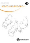
sedeo pro
1011651D
 | 31
Sedeo Pro
© 2011 Handicare
All rights reserved.
The information provided herein may not be reproduced and/or published in any form, by print,
photoprint, microfilm or any other means whatsoever (electronically or mechanically) without the prior
written authorization of Handicare.
The information provided is based on general data concerning the construction known at the time of
the publication of this manual. Handicare executes a policy of continuous improvement and reserves
the right to changes and modifications.
The information provided is valid for the product in its standard version. Handicare can therefore not
be held liable for any damage resulting from specifications of the product deviating from the standard
configuration. Illustrations contained in the manual may deviate from the configuration of your product.
The information made available has been prepared with all possible diligence, but Handicare cannot
be held liable for any errors contained in the information or the consequences thereof.
Handicare accepts no liability for loss resulting from work executed by third parties.
Names, trade names, trademarks etc. used by Handicare may not, as per the legislation concerning
the protection of trade names, be considered as being available.
2011-01
32 | 32
1Introduction
1.1 This manual
1.2 Symbols used in this manual
33
33
33
2Safety
2.1Temperature
2.2 Indications on the seating system
34
34
34
3
35
35
General description
3.1 Sedeo Pro product description
4Use
4.1 Adjustment of the seating system (by the user/attendant)
4.2 Getting into and out of the wheelchair (forward transfer)
4.3 Getting into and out of the wheelchair (sideways transfer)
4.4 Options / accessories
4.5 Reducing the seating system in size for transportation purposes
4.6 Setting up the seating system following transportation
36
36
39
39
40
42
44
5
46
46
46
47
47
47
48
49
50
50
53
54
55
56
56
57
58
58
Seating system adjustments (to be carried out by a professional)
5.1 Seat depth
5.2 Seat width
5.3 Backrest angle
5.4 Backrest height
5.5 Standard and manually elevating legrest
5.6 Comfort legrest
5.7 Central legrest
5.8 Central legrest gas spring adjustment
5.9 Armrest assembly
5.10Adjusting the centre of gravity
5.11Headrest
5.12Fixed / swing-away controller bracket
5.13Abduction support
5.14Backrest with adjustable straps - flexible
5.15Thoracic support
5.16Thigh support
5.17Attaching the lap strap
6Maintenance
6.1 Cleaning the upholstery
60
60
7Troubleshooting
61
8
Specifications
8.1 CE declaration of conformity 8.2 Technical information
62
62
62
9.
Provisions of warranty
64
Introduction | 33
1
Introduction
1.1 This manual
This user manual will help you to use and
maintain your seating system safely This user
manual is a supplement to Handicare’s general
wheelchair user manual.
Where necessary this user manual refers to
other manuals as shown below:
&Wheelchair: Refers to the general wheelchair user manual.
&Controller: Refers to the user manual for the controller (only applicable for power wheelchairs).
Read this user manual and the other user
manuals referred to carefully before using
the product. If one of the user manuals was
not included with your wheelchair, please
contact your dealer immediately.
In addition to this user manual, there is also a
service manual for qualified specialists.
CONTACT HANDICARE IF YOU HAVE A
VISUAL IMPAIRMENT.
1.2 Symbols used in this manual
Note!
Pointing out possible problems to the user.
Caution!
Advice for the user to prevent damage to the
product.
Warning!
Warnings for the user to prevent personal in
jury.
Not following these instructions may result
in physical injury, damage to the product or
damage to the environment!
34 | Safety
2
Safety
Warning!
Always follow the instructions given next to
the warning symbols! Failure to follow these
instructions may result in physical injury,
damage to the wheelchair or damage to the
environment. Where possible the warning
symbols have been placed in the applicable
paragraphs.
Be carefull when swing away/flip up parts.
Contact with moving parts should be avoided.
Caution!
Parts of the wheelchair that are intended, for
service or repair, to be removed without the
use of tools (e.g. armrest, legrest) can have
an adverse effect on the support of the user if
they are missing or not placed back in the right
position.
2.1 Temperature
Warning!
Avoid exposing the wheelchair to direct sunlight
for extended periods of time. Some parts of the
wheelchair, such as the seat, the backrest and
the armrests assembly, complete, can become
hot if exposed to the sun for too long. This may
cause burns or skin irritation.
2.2 Indications on the seating
system
The wheelchair must not be lifted
up by the armrests assembly,
complete and/or legrests.
The stability of the wheelchair is
influenced by the adjustment of the
seating system's centre of gravity.
Such adjustments should be made
by professionals only.
General description | 35
3
General description
3.1 Sedeo Pro product description
The wheelchair is fitted with a Sedeo Pro
seating system. The Sedeo Pro seating system
provides excellent support for the head, torso,
arms and legs. Optimal body support ensures
maximum independence for the wheelchair
user.
The wheelchair must be adjusted by a qualified
specialist. Incorrect settings may have negative
consequences for seating posture.
Tools supplied
A T30 Torx key is supplied with the seating
system. This can be used by a professional for
adjusting all of the seating system settings. The
T30 Torx key (A) can be found on the frame at
the location indicated in the illustration.
Caution!
Please study this manual carefully before using
the seating system.
A
Key to symbols
Loosen by one turn with wing-nut
Tighten by one turn with wing-nut
Loosen by one turn with torx
Tighten by one turn with torx
Sedeo i 1
Step 1, 2 etc.
An arrow, as part of an illustration, indicates
that the component in question moves or needs
to be moved in the direction indicated.
Notes on "Key to symbols"
Each illustration includes icons and numbering
to indicate what needs to be done and in which
order.
Note!
There are calibration marks on various parts of
the seating system. The ex-factory settings are
indicated.
36 | Use
4
Use
4.1 Adjustment of the seating system
(by the user/attendant)
Manually recling backrest (by attendant) 1. Squeeze (A).
2. Adjust (B) to the desired position.
1
2
A
Note!
Keep squeezing (A).
B
3. Release (A).
Sedeo g 1
Manually recling backrest (by user) 1. Squeeze (A).
2. Lean forwards or backwards to adjust (B) to the
desired position.
Note!
Keep squeezing (A).
2
B
3. Release (A).
Power reclining backrest
Power reclining backrest is adjusted by moving the
electronic joystick. Please refer to the controller owners
manual for operating instructions.
1
A
Sedeo g 2
Sedeo Original comfort legrests knee angle
The angle of the comfort leg rests can be adjusted
independently of each other.
1. Push handle (B) forwards.
2. Lift your leg.
3. Release the handle when in the desired position.
Sedeo power elevating legrests
Knee angle is adjusted by moving the electronic
joystick. Please refer to the controller owners manual
for operation instructions.
B
A
Use | 37
Sedeo Original central leg rest gas spring
adjustment knee angle
1. Press gas spring handle (C).
2. Adjust the leg rest to the desired position.
3. Release the gas spring (C).
Moving the controller bracket inwards
1. Push (A) inwards until hearing a click.
A
Sedeo g 5
Swing away the controller bracket
1. Push (A) outwards until hearing a click.
Note!
Swinging back the controller bracket will allow you to
pull up close to a table. Full operation of the controller
remains possible.
A
Sedeo g 6
38 | Use
Push handle height
1. Loosen (A) by one turn.
2. Slide (B) into the desired position.
3. Tighten (A).
2
B
B
2
A
1
3
Sedeo g 7
Angle adjustable push bar
1. Loosen (A) by one turn.
2. Slide (B) into the desired position.
3. Tighten (A).
Warning!
Do not use the push bar to tip the whole chair to the
rear (in order to mount a pavement, for example).
The push bar is not suitable for such use.
2
A
1
B
3
Sedeo g 29
Hemiplegia armrest
1. Pull (A) out of the locked position and twist (B) into
the desired position.
A
Note!
Ensure that (B) is properly secured!
1a
1b
B
Sedeo g 30
Use | 39
4.2 Getting into and out of the
wheelchair (forward transfer)
Warning!
Do not stand on the footplates. Putting your full weight
on the footplates may lead to wheelchair damage and
to hazardous situations, including the wheelchair tipping
up.
Sedeo Original standard legrest
1. Fold up the foot supports
2. Swing the calf plates to the side (if applicable)
3. If possible, swing the legrests to the side
4. Seat yourself in the chair
Flipping up the central legrest footplate
1. Flip up (A).
A
Sedeo g 14
4.3 Getting into and out of the
wheelchair (sideways transfer)
2
B
Note!
Some versions of the controller will need to be swung
aside.
Removing the armrest assembly
1. Tip (A) downwards.
2. Remove (B).
A
1
Sedeo g 15
40 | Use
Folding back the armrest assembly
1. Press (A).
2. Fold (B) to the rear.
B
2
Caution!
Remove the tray before folding back the armrest
assembly.
Warning!
Do not lean on the armrest when folded back.
1
A
Sedeo g 16
4.4 Options / accessories
2
Removing/positioning the headrest
1. Lift (A).
2. Slide (B) out of or into (C).
3. Push (A) down.
B
Note!
Always slide the headrest until it comes to a stop in the
bracket.
1
A
Sedeo g 17
Flip down the abduction support
1. Pull (A) out of the locked position and flip down (B)
2. Release (A).
Flip up the abduction support
3. Pull (A) out of the locked position and flip up (B).
4. Release (A) in the locked position.
3b
B
1b
Note!
Ensure that (B) is properly secured!
A
1a 3a
Sedeo g 31
Use | 41
Folding back the thoracic support
1. Press (A) to fold back (B).
B
A
1
2
Sedeo g 32
Removing the thigh support
1. Loosen (A) by one turn.
2. Remove (B).
2
B
A
1
Sedeo g 33
42 | Use
E
A
B
C
D
Sedeo g 25
4.5 Reducing the seating system
in size for transportation
purposes
A. Seat (2,5 kg)
B. Backrest (2,5 kg)
C. Armrest assembly (2 kg)
D. Legrest (1,7 kg)
E. Headrest (1,3 kg)
Warning!
The wheelchair can be reduced in size for
transportation without a passenger. Any
components of the seating system that can be
detached easily should be removed. Store away
such components safely so that they can not
cause injury or damage, or become damaged
themselves.
Use | 43
Removing the seat
1. Pull (A) upwards and forwards.
A
Sedeo i 4
Removing the back cushion
1. Turn (A) and (B).
2. From the bottom, pull (C) forwards and upwards and
remove.
C
1
1
2
A
B
Sedeo g 19
Folding the backrest fully forward
1. Loosen (A).
B
Note!
Do not remove (A).
2
2. Fold (B) fully forward.
Note!
If necessary, first remove the back cushion and/or the
armrest assemblies.
A
1
Sedeo g 20
44 | Use
Removing Sedeo footrests / legrests
The following steps apply to Sedeo swingaway
footrests, manual elevating legrests and power
elevating legrests
1. Remove the velcro calf strap from one side of the
footrests (if calf strap is installed)
2. Push the catch (A) to the rear in order to unlock the
leg rest.
3. Swing the leg rest outwards.
4. Remove the leg rest (B) from its bracket by lifting.
A
B
You should hear a click when replacing the leg rest.
This indicates that the leg rest has locked into place.
Removing the armrest assembly
1. Tip (A) downwards.
2. Remove (B).
2
B
A
1
Sedeo g 15
4.6 Setting up the seating
system following transportation
Positioning the armrest assembly
1. Slide (A) onto (B).
2. Push (C) upwards.
A
2
1
C
B
Sedeo g 21
Use | 45
Positioning the backrest for use
1. Fold (A) upwards and backwards.
2. Tighten (B).
1
A
B
2
Sedeo g 23
Positioning the back cushion
1. Hook (A) behind (B).
2. Turn (C).
Caution!
Ensure that the back cushion is firmly in position
(handles upwards).
1
A
1
A
B
B
C
C
2
2
Sedeo g 24
Positioning the seat
1. Slide (A) and (B) over (C) and (D)
2. Push (E) downwards.
Caution!
Ensure that (C) and (D) at the back of the seat hook
under the bolt heads.
2
A
E
C
D
C
B
1
A
Sedeo i 7
46 | Seating system adjustments (to be carried out by a professional)
5
Seating system adjustments
(to be carried out by a
professional)
A L+R
1
Note!
There are calibration marks on various parts of the
seating system. The ex-factory settings are indicated.
3
B
5.1 Seat depth
2
Backrest adjustment
1. Loosen (A) by one turn.
2. Adjust (B) to the desired position.
3. Tighten (A).
Sedeo i 48
Seating system adjustment
1. Remove the seat (see "Use - Reducing the seating
system in size for transportation purposes").
2. Remove the screws (B).
3. Move (C) and (D).
4. Tighten the screws (B).
5. Replace the seat (see "Use - Setting up the seating
system following transportation").
B 4x L+R
2
3
4
D 2x
C 2x
Sedeo i 49
5.2 Seat width
1. Loosen (A) by one turn.
2. Slide (B) into the desired position.
3. Tighten (A).
B
A
1
2
3
Sedeo i 52
Seating system adjustments (to be carried out by a professional) | 47
5.3 Backrest angle
1. Turn (A) in order to adjust (B).
B
A
Sedeo i 9
5.4 Backrest height
1. Loosen (A) by one turn.
2. Adjust (B) to the desired position.
3. Tighten (A).
2
A
B
1
3
Sedeo i 10
5.5 Standard and manually elevating
legrest
Legrest width
1. Loosen (A) by one turn.
2. Slide (B) into the desired position.
3. Tighten (A).
B
2
A
1
3
Sedeo i 11
48 | Seating system adjustments (to be carried out by a professional)
Lower leg length
1. Loosen the setscrew (A) a few turns with a 4 mm
Allen key.
2. Slide the footplate (B) in the desired position.
3. Tighten the setscrew (A) securely.
B
A
Caution!
Ensure that there is sufficient free space under (B) for
the wheelchair to drive over obstacles.
Footplate angle
1. Loosen the Allen bolt (C) a few turns with a 6 mm
Allen key, so that the teeth of the hinge come
completely free.
2. Adjust the desired footplate angle (D) and push the
hinge manually together again.
3. Tighten the Allen bolt (C) securely.
D
B
A
E
Footplate depth
The footplate is secured asymmetrically. The left and
right footplate can be exchanged.
1. Loosen the setscrew (A) with a 4 mm Allen key.
2. Remove the footplate together with the profile.
3. Slide the footplate in the top tube of the other
legrest.
4. Tighten the setscrew (A) securely.
Caution!
Make sure that the castor wheels do not touch the
footplates when manoeuvring. If this is the case,
the legrests must be brought forward. There must
be at least 1 cm between the castor wheels and the
footplates.
C
B
C
A
D
5.6 Comfort legrest
Calf pad height
1. Loosen the Allen bolt (A) a few turns with a 4 mm
Allen key.
2. Slide the calf pad (B) in the desired position.
3. Tighten the Allen bolt (A) securely.
Seating system adjustments (to be carried out by a professional) | 49
5.7 Central legrest
Lower leg length
1. Loosen (A) by one turn.
2. Slide (B) into the desired position.
3. Tighten (A).
Caution!
Ensure that there is sufficient free space under (B) for
the wheelchair to drive over obstacles.
A L+R
1
3
B
2
Sedeo i 19
Knee angle
1. Loosen (A) by two turns.
2. Adjust (B) to the desired angle.
3. Tighten (A) by two turns.
Caution!
Change the height or knee angle if the footplate
touches the castor wheels.
A L
1
3
B
2
Sedeo i 20
Ankle angle
1. Flip up (A).
2. Turn (B) in order to adjust the ankle angle as
desired.
3. Fold (A) down.
A
1
B 2
Sedeo i 21
50 | Seating system adjustments (to be carried out by a professional)
Calf pad height
1. Loosen (A) by one turn.
2. Slide (B) into the desired position.
3. Tighten (A).
2
B
A L+R
1
3
Sedeo i 22
5.8 Central legrest gas spring
adjustment
Lower leg length
1. Loosen the knob (B).
2. Slide the footplate (A) in the desired position.
3. Tighten the knob (B) securely.
Note!
Make sure that there is sufficient free space under the
footplate to operate the wheelchair over obstacles
5.9 Armrest assembly
Armrest height
1. Loosen (A) by one turn.
2. Adjust (B) to the desired position.
3. Tighten (A).
Note!
Ensure that the arms are supported well, without the
shoulders being pushed upwards.
2
B
A
1
3
Sedeo i 23
Seating system adjustments (to be carried out by a professional) | 51
Armrest depth
1. Loosen (A) by one turn.
2. Slide (B) into the desired position.
3. Tighten (A).
Note!
Position the armrest further back in order to obtain more
space for transfers.
B
2
A
1
3
Sedeo i 24
Armrest depth
1. Loosen (A) by one turn.
2. Slide (B) into the desired position.
3. Tighten (A).
B
2
A 1
3
Sedeo i 25
Armrest width, with or without controller bracket
To remove:
1. Loosen (A).
2. Remove (B).
B
2
A 1
Sedeo i 31
52 | Seating system adjustments (to be carried out by a professional)
3. If applicable, loosen (C) by one turn.
4. Remove (D) if applicable.
D
4
C
3
Sedeo i 32
5. Loosen (E) by one turn.
6. Remove (F).
F
6
E
5
Sedeo i 33
To position:
1. Slide (A) together with (B) or (C) onto (D).
D
Note!
Ensure that the ridge on the terminal block falls into the
opening
1
A
B
C
Sedeo i 34
Seating system adjustments (to be carried out by a professional) | 53
2. Adjust the depth of (A) and tighten (E).
3. Position the controller bracket.
4. Position the armrest.
A
E
2
Sedeo i 35
Side panel height
1. Loosen (A) by one turn.
2. Adjust (B) to the desired position.
3. Tighten (A).
B
2
A
1
3
Sedeo i 39
5.10Adjusting the centre of gravity
Warning!
The stability of the wheelchair is influenced by the
adjustment of the seating system's centre of gravity.
Such adjustments should be made by professionals
only.
1. Loosen (A) by one turn.
2. Slide (B) forwards or backwards.
3. Tighten (A).
Note!
If the user's weight distribution is average, then
the centre of gravity should be adjusted to the same
setting as the seat depth.
For better sliding release the seat depth adjustment
2
B
A
1
3
Sedeo i 40
54 | Seating system adjustments (to be carried out by a professional)
5.11Headrest
Headrest height
1. Lift (A).
2. Slide (B) into the desired position.
3. Push (A) down.
2
B
1
A
A
3
Sedeo i 41
Adjusting the memory setting
1. Loosen (C) by one turn.
2. Slide (D) as far down as possible.
3. Tighten (C).
D
C
1
2
3
Sedeo i 42
Headrest position
1. Loosen (A) by one turn.
2. Adjust (B) to the desired position.
3. Tighten (A).
Note!
Correct the headrest height and tilt the headrest
cushion as required.
C
3
B
2
A 1
4
Sedeo i 43
Seating system adjustments (to be carried out by a professional) | 55
Headrest cushion width
1. Loosen (A) by one turn.
2. Slide (B) into the desired position.
3. Tighten (A).
2
B
A 1
3
Sedeo i 44
5.12Fixed / swing-away controller
bracket
Depth
1. Loosen (A) by one turn.
2. Slide (B) into the desired position.
3. Tighten (A).
B
2
A 1
3
Sedeo i 45
Height (1)
1. Loosen (A) by one turn.
2. Slide (B) into the desired position.
3. Tighten (A).
2
B
A 1
3
Sedeo i 46
56 | Seating system adjustments (to be carried out by a professional)
Height (2)
1. Loosen (C) by one turn.
2. Slide (D) into the desired position.
3. Tighten (C).
2
D
C 1
3
Sedeo i 47
5.13Abduction support
A
Adjust the abduction support as follows:
1. Loosen the Torx screw.
2. Adjust the part to the desired position.
3. Tighten the Torx screw.
A/a. Height adjustment.
B/b. Depth adjustment.
B
b
a
Sedeo i 53
5.14Backrest with adjustable straps flexible
The sides of the backrest with adjustable straps can
be adjusted as follows:
1. Loosen the four Torx screws.
2. Adjust the sides to the desired position.
3. Tighten the four Torx screws.
A/a.
Angle adjustment.
a
A
Sedeo i 54
Seating system adjustments (to be carried out by a professional) | 57
5.15Thoracic support
Adjust the thoracic support as follows:
1. Loosen the Torx screw.
2. Adjust the part to the desired position.
3. Tighten the Torx screw.
A/a.
B/b.
a
A
Rough adjustment of width
Height adjustment
B
b
A/a.
B/b.
Sedeo i 55
Adjustment of bracket depth
Adjustment of cushion depth
B
b
A
a
Sedeo i 56
A/a.
B/b.
Adjustment of cushion angle
Fine adjustment of width
A
b
a
B
Sedeo i 57
58 | Seating system adjustments (to be carried out by a professional)
5.16Thigh support
Adjust the thigh support as follows:
1. Loosen the Torx screw.
2. Adjust the part to the desired position.
3. Tighten the Torx screw.
A/a.
B/b.
A
a
Depth adjustment
Width adjustment
B
b
Sedeo i 58
A/a.
B/b.
C/c.
D/d.
Height adjustment
Memory setting adjustment
Bracket position adjustment
Cushion position adjustment
D
d
C
C
Tip!
The height adjustment can be fixed using the memory
setting.
c
A
b
B
a
Sedeo i 59
5.17Attaching the lap strap
Attaching to the slider
1. Loosen 2x (A) and remove (A) from the left-hand
and right-hand sliders.
2. Place (B) in the sliders and tighten in the desired
position.
3. Position 2 x (A) back in the sliders and tighten (A).
1
3
2
A
B
Sedeo i 62
Seating system adjustments (to be carried out by a professional) | 59
Attaching to the seating frame
1. Attach (A) to the seating frame using a screw on the
left and on the right.
A
Sedeo i 63
Warning!
Ensure that the lap strap is adjusted to the wheelchair
user. The strap must fit snugly across the hips at an
angle of approximately 45°.
Ensure that the strap is clean at all times and that the
locking mechanism is working properly. The strap and
the locking mechanism can be cleaned using a damp
cloth.
45°
If the strap is positioned above the hips and across
the soft part of the user's belly, then this can result
in seating posture being incorrect and the user
slumping in the seat.
Sedeo i 64
Never use the lap strap as a seatbelt when using
transport.
Sedeo i 65
60 | Maintenance
6
Maintenance
It is recommended that you have your wheelchair
serviced by your dealer once a year or, in the case of
intensive use, once every six months.
6.1 Cleaning the upholstery
Clean the upholstery using a damp cloth and household
soap. Then rub dry using a soft, dry cloth.
PU parts
Clean the armrests, side cushions etc. using a damp
cloth and household soap. Then dry the parts using a
soft cloth.
Seat and backrest cushion upholstery
Follow the washing instructions on the covers:
For the incontinence cover see figure 1.
For the comfort cover see figure 2.
Warning!
Do not use organic solvents such as thinner, benzine or
white spirit.
Do not chemically clean the upholstery. Do not iron or
spin-dry the upholstery.
Stretch Rubber
58% Knitted Polyester
42 % FR Polyurethane
Fabric
Backing 100% Polyester
Coating 100% PVC
Care instructions
Do not use cleaning materials that
contain solvents
40
9005849
Figure 1
Stretch Fabric
35% Polyester
65% Dioleen Safe
Fabric
Backing 100% Polyester
Coating 100% PVC
Care instructions
Do not use cleaning materials that
contain solvents
40
9005850
Figure 2
Troubleshooting | 61
7
Troubleshooting
If there is a problem with your seating system,
contact you dealer.
62 | Specifications
8
Specifications
8.1 CE declaration of conformity
The product is in conformity with the provisions of the Medical Devices Directive and
carries the CE mark.
The product also meets the following requirements and standards. This has been verified by
independent test organizations.
1. EN 12183 (2009) Manual wheelchairs or EN 12184 (2009) Electrically powered wheelchairs.
2. ISO 7176-8 Requirements for impact, static and fatigue strength.
3. ISO 7176-9 Climatic tests for electric wheelchairs and scooters.
4. ISO 7176-16 Requirements for resistance to ignition of upholstered parts.
5. ISO 7176-19 Crash test.
6. EN-ISO 10993-5 (1999-11) Biological evaluation of medical devices.
7. EN 1021 1,2 Assessment of the ignitability of upholstered furniture. Ignition source: smouldering
cigarete/match flame equivalent.
8.2 Technical information
Seating system
User Weight
160 kg
Seat width
400 - 540 mm (option 520 - 680 mm)
Seat depth
420 - 600 mm
Point of gravity
95 mm
Seat
Seat cushion depth position
-20 mm / 0 / +20mm
Backrest
Backrest height
500 - 640 mm
Backrest angle
89 - 128°
Backrest recline (option)
89 - 128°
Armrest
Armrest pad width
-20 / 0 mm per side
Armrest pad height
170 - 290 mm (option 270 - 390 mm)
Armrest depth
80 mm
Armrest pad depth
controller bracket side 50 mm
non controller bracket side 160 mm
Side support
Side cushion height
65 mm
Central legrest
Lower leg length
350 - 515 mm
Knee angle
30 - 110°
Ankle angle
+20° till -40°
Central calf support height (option)
120 mm
Specifications | 63
Manually elevating central legrest
Lower leg length
430 - 550 mm
Knee angle
35 - 95°
Standard legrest (set)
Lower leg length
360 - 530 mm
Knee angle
70°
Ankle angle
0 - 180°
Elevating and electrical elevating legrest (set)
Lower leg length
360 - 540 mm
Knee angle
70 - 0°
Ankle angle
0 - 180°
Calf support height
120 mm
Headrest
Headrest height (memory)
170 mm
Headrest depth
180 mm
Headrest vertical angle
-45° - 45°
Headrest width (option)
standard head rest -20 - 20 mm
width adjustable head rest -110 - 110 mm
Controller bracket
Controller bracket height
60 mm
Controller bracket depth
35 mm
Controller bracket swing away
Controller bracket height
50 mm
Controller bracket depth
35 mm
Controller position angle
0 - 45°
Pushbar
Pushbar height
185 mm
Hemiplegia
Hemiplegia armrest angle (option)
0 - 45°
Abduction support
Abduction support height
60 - 120 mm
Abduction support depth
60 - 110 mm
Thoracic support
Thoracic support width
-60 - 0 mm
Thoracic support height
200 - 400 mm
Thoracic support depth
20 - 70 mm
64 | Provisions of warranty
9. Provisions of warranty
The provisions of warranty and liability
applicable to the seating system are identical to
those incorporated in the wheelchair manual.
(& Wheelchair)
| 65
66


67
Dealer:
Serienummer: