1
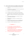
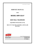
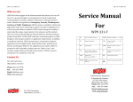
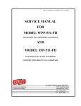
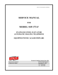
SSW-341-Fr1-XFD-ISSUE5.0
SERVICE MANUAL
FOR
MODEL SSW-341-Fr1
MINI WALL TELEPHONE
EQUIPPED WITH SIDE-MOUNTED, RECEIVER-OPERATED,
MAGNETIC HOOKSWITCH; INTERNAL VOLUME CONTROL
AND NOISE REDUCTION CIRCUIT; XFD PCB.
Serving the Telephone Industry Since 1930
Communication Equipment
& Engineering Company
519 West South Park Street
Okeechobee, FL 33313
Voice: 954-587-5430
Fax
954-587-5440
Issue 4.00
IMPORTANT INFORMATION
FOR
CUSTOMER
Please fill in before you continue.
The following information is necessary when calling CEECO for assistance.
MODEL NUMBER
SSW-341-Fr1
SERIAL NUMBER
DATE MANUFACTURED
LOCATION INSTALLED
For us to better serve you, please have this information available when calling for
technical support.
CEECO
Communication Equipment & Engineering Company
519 West South Park Street
Okeechobee, FL 34972
(863)-357-0798 Voice
(863)-357-0006 Fax
TABLE OF CONTENTS
CEECO
Communication Equipment and Engineering Company
PROPRIETARY
2
Issue 4.00
SECTION
PAGE
1.0
INTRODUCTION................................................................................................. 4
2.0
GENERAL DESCRIPTION ................................................................................ 4
3.0
OPERATION ........................................................................................................ 4
4.0
RECOMMENDED TOOLS AND TEST EQUIPMENT .................................. 5
5.0
INSTALLATION NOTES AND ASSEMBLY INSTRUCTIONS ................... 6
6.0
TESTING............................................................................................................... 7
7.0
SPECIFICATIONS............................................................................................... 8
8.0
PARTS LIST ......................................................................................................... 9
9.0
FCC NOTICE...................................................................................................... 10
10.0
REPAIR AND RETURN INFORMATION ..................................................... 11
11.0
WARRANTY POLICY ...................................................................................... 12
CEECO
Communication Equipment and Engineering Company
PROPRIETARY
3
Issue 4.00
1.0
INTRODUCTION
The practices in this manual provide installation and maintenance information for
Model SSW-341-Fr1, which is a Stainless Steel Mini Wall Telephone.
The information in this manual is subject to change without notification.
For information not included in this manual, please call or write:
CEECO
Customer Service
519 West South Park Street
Okeechobee, FL. 34972
(863)-357-0798 Voice
(863)-357-0006 Fax
2.0
GENERAL DESCRIPTION
The CEECO model SSW-341-Fr1 is a Mini Wall Telephone equipped with a
metal button alpha-numeric keypad, tone dialer, side-mounted, receiver-operated,
magnetic hookswitch with chrome plated handset cradle, internal volume control
and noise reduction circuit. It is designed for special applications where a
telephone must be sturdy and attractive, and also consume less than 4” in depth
from the mounting surface. The internal volume control is operated by a push
button mounted on the face of the housing. The button bears a universal volume
control symbol on its face. The built in noise reduction circuit helps reduce
background noise. Rather than the standard mechanical hookswitch, these phones
are equipped with a receiver-operated magnetic hookswitch, which translates to
no moving parts and less chance of intrusion. The slim 3.5” of depth and the
side-mounted handset make this unit ideal for hallways and corridors where the
special considerations and inadvertent off-hook conditions are a concern.
3.0
PROGRAMMING
This telephone comes from CEECO already programmed for operation.
Following the programming described hereafter is only necessary to change or
activate desired features. Short of that, the phone is ready to install and use.
Connect the CEECO XFD Series Telephone to the Telephone Line provided by
your local Telephone Company or to analog type PABX Station.
Using another Telephone (Different Telephone Line, or Cell Phone) equipped
with a Touch Tone Keypad, call the Telephone equipped with the CEECO XFD.
CEECO
Communication Equipment and Engineering Company
PROPRIETARY
4
Issue 4.00
PROGRAMMING CONT’D…
After the Telephone equipped with the CEECO XFD rings 4 times, answer
the Telephone.
From the local or remote Keypad, press the # key, followed by the five (5) digit
Pass Code (Factory Default: 23326*). Two (2) beeps will be heard indicating a
valid Pass Code entry, Five (5) beeps will only be heard when errors occur.
Review the programming feature commands below and make entries according to
the particular requirements.
3.1 Programming Feature commands:
•
Clear Memory
#97*
•
•
Transmitter Muted Off Hook
Transmitter Not Muted Off Hook
#560* (Default)
#561*
•
•
Tone Dial Mode
Rotary Dial Mode
#570* (Default)
#571* (Rotary 10pps)
•
•
No background Noise Reduction
Background Noise Reduction
#590* (Default)
#591*
•
Change Pass Code
#31x* (x = 5 Digits; 0 – 9)
*
4.0
Keys to enter:
When finished, simply hang up and the phone is ready for operation as
programmed.
RECOMMENDED TOOLS AND TEST EQUIPMENT
Volt/Ohm Meter
1/4" Nut Driver
Flat Blade Screw Driver
Security Tool CEECO Part Number 301-037
CEECO
Communication Equipment and Engineering Company
PROPRIETARY
5
Issue 4.00
5.0
INSTALLATION NOTES AND ASSEMBLY INSTRUCTIONS
5.1
Using a 301-037 security tool (sold separately) loosen and remove the
security screw.
5.2
The security tool is for a standard 5/32" button head screw generally used
on the framework of the phone booths.
5.3
Separate the cover assembly from the backplate assembly.
5.4
The backplate assembly may be installed on any standard backboard.
5.5
Run the inside station wire through the backplate assembly and terminate
on the RJ11C modular jack on the backplate, as depicted on the following
page.
5.6
The use of a gas tube station protector is recommended. The station
ground should not exceed 50 ohms.
5.7
Plug the modular line cord from the cover assembly into the RJ11C
terminal block.
5.8
Dress the line cable away from the security screw and install the cover
assembly by inserting the tabs into the slots on top of the backplate.
5.9
Secure the cover assembly by tightening the security screw.
*****WARNING*****
A.
Never install telephone wiring during a lightning storm.
B.
Never install telephone jacks in wet locations unless the jack is
specifically designed for wet locations.
C.
Never touch uninsulated telephone wires or terminals unless the
telephone line has been disconnected at the network interface.
D.
Use caution when installing or modifying telephone lines.
CEECO
Communication Equipment and Engineering Company
PROPRIETARY
6
Issue 4.00
5.10 Modular Jack/Telephone Line Wiring Diagram:
6.0
TESTING
6.1
Connect the phone to a phone line or a DTMF phone test set.
6.2
Lift the handset, dial tone is heard.
6.3
Dial a number. (The transmitter is muted while the phone is dialing.)
6.5
Press the volume control button. Volume should increase each time and
reset on the fourth press of the button. 18-20dB overall gain.
6.6
Normal phone conversation is allowed. Place the handset on hook.
Volume control will reset to normal.
6.7
Place a call into the phone.
6.8
Normal phone conversation is allowed.
CEECO
Communication Equipment and Engineering Company
PROPRIETARY
7
Issue 4.00
7.0
SPECIFICATIONS
INPUT POWER:
C.O. Line Powered
LOOP CURRENT:
20mA min to 80mA max
IMPEDANCE:
600 ohms
SIGNALING:
DTMF
HEARING AID
COMPATIBLE:
Meets EIA standards
ENVIRONMENTAL:
Temperature 0°C to 50°C
Humidity
20%-90% non-condensating
RINGER EQUIVALENCY:
0.4A
TYPE JACK:
RJ11C
TELEPHONE COVER:
Brushed 16 ga. Stainless Steel
DIMENSIONS:
5" Wide x 10 3/4" High x 3.5" Deep/
With Handset on hook
MOUNTING:
Vertical surface mount
WEIGHT:
6 lbs.
FCC REGISTRATION:
BW-88T7-13717-TE-T
UL LISTED NO.:
6OF5
CEECO
Communication Equipment and Engineering Company
PROPRIETARY
8
Issue 4.00
8.0
PARTS LIST
QUANTITY PART NUMBER
DESCRIPTION
1
301-11708
Stainless Steel Mini Housing
1
705-100
Metal Button Key Pad
1
301-106-32
Handset w/ Armored Cord & Steel Lanyard
1
401-009
Ringer
1
301-592
Receiver-operated Magnetic Hookswitch
1
301-018
Modular Cord
1
321-017r1
Stainless Steel Backplate
1
321-016
1/4 - 20 x 3/4 Security Screw
1
301-005
Cable Ferrule
1
301-052
Grommet
1
301-054
Modular Jack
1
301-18067
XFD Printed Circuit Board
1
301-6077
Volume Control Button w/Volume Symbol
301-037
Security Tool
ACCESSORIES:
1
OPTIONS:
301-106-18 (Prison)
18” Armored Cord Handset w/Steel Lanyard
CEECO
Communication Equipment and Engineering Company
PROPRIETARY
9
Issue 4.00
9.0
FCC NOTICE
9.1
FCC REGISTRATION AND REPAIR INFORMATION
Your new telephone has been registered with the Federal Communication
Commission (FCC) in accordance with Part 68. The FCC requires that
you be advised of certain requirements involving the use of this telephone.
9.2
CONNECTION WITH THE NATIONWIDE TELEPHONE
NETWORK
The FCC requires that you connect this telephone to the Nationwide
Telephone Network through a registered jack provided by the telephone
company in your area. This jack is a modular outlet, which you can order
from your local telephone company.
9.3
NOTIFICATION TO THE TELEPHONE COMPANY
Before connecting this telephone, the FCC requires that you notify your
local telephone company business office. The number is in the front of
your phone book.
Tell them:
The "line" to which you will connect the telephone (that is, your phone
number) and the telephone's FCC registration number and ringer
equivalence number. These numbers are listed in section 7.00.
The FCC further requires that you notify your local telephone company
when permanently disconnecting this telephone.
CEECO
Communication Equipment and Engineering Company
PROPRIETARY
10
Issue 4.00
10.0 REPAIR AND RETURN INFORMATION
10.1
WARRANTY REPAIR
Any device returned requiring warranty service, repair or credit must be
accompanied with a "Return Material Authorization" (RMA) Form. It
must include: RMA Number, return shipping instructions, original
purchase order number, serial number and special marking instructions. A
tag with the trouble observed must be attached to the defective unit. This
information must be inside the shipping container.
10.2
DIRECT ALL INQUIRES TO:
CEECO
Repair Department
519 West South Park Street
Okeechobee, FL 34972
(863)-357-0798
10.3
NON-WARRANTY REPAIR
CEECO will repair equipment out of warranty for a set charge plus parts.
The customer must pay the shipping costs both directions.
10.4
RETURN FOR CREDIT
Material may be returned for credit only with prior approval. Material
authorized for return is subject to a 20% restocking charge based on the
manufacturer's list price. Return Material Authorization must be
requested no later than 30 days after original shipment. Items returned for
credit must be returned in their original shipping container.
CEECO
Communication Equipment and Engineering Company
PROPRIETARY
11
Issue 4.00
11.0 WARRANTY POLICY
11.1
GENERAL
CEECO guarantees its products to be free from defects in material and
workmanship for a period of 365 days from the date of original purchase.
CEECO's obligation under this warranty is limited to repair or
replacement of any part found to be defective by CEECO.
UNDER NO CIRCUMSTANCES shall CEECO be liable for loss,
damage, cost of repair or consequential damages of any kind, which have
been caused by neglect, abuse or improper operation of equipment.
CEECO will repair or replace any unit during this period if found to be
defective for reasons other than abuse and improper use or improper
installation. It is the buyer’s responsibility to return the defective unit to
the factory. CEECO will then repair or replace any defective parts and
return them to the buyer free of charge.
11.2
PRINTED CIRCUIT BOARDS
Printed circuit boards should not be repaired in the field. If a unit is found
to be faulty, replace it with another unit and return the faulty unit to
CEECO for repair. Modifications by any one other than CEECO will void
the warranty.
CEECO
Communication Equipment and Engineering Company
PROPRIETARY
12