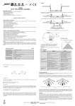
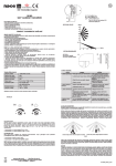
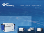
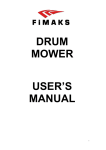
1
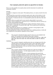
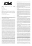
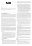
NEBİMAK LPG FEED BACK VAPORIZER
NBH XX SERIES USER MANUAL
II 2G Ex d IIA T3
NBH-XX
NBH-XX
NBH-XX
Capacity Kg/h
20
30
50
NBH
Power Kw/h
3,5
5,5
7,5
XX
Voltage
400V AC
400V AC
400V AC
Design Pressure
PN 40
PN 40
PN 40
Max Pressure
17,2 BAR
17,2 BAR
17,2 BAR
SERIES
Capacity(20,30,50)Kg/h
Company Code
Number of Pages
Date
Signature
: 14
: 04.08.2010
TABLE OF CONTENTS
I. INFORMATION FOR CUSTOMERS................................................................................................................3
2. DENOTATION OF THE FUEL DISPENSER…………………………..………………..…………………………………………………..……4
3. LP GAS, PRECAUTIONS………………………………………………………………...............................................................4
LP Gas, LPG ..............................................................................................................................................................4
Precautions ..............................................................................................................................................................4
4. PRE-INSTALLATION,INSPECTION .......................................................................................................... .....5
5. YOUR VAPORIZER ..................................................................................................................................... 5
5.1 Function of the Feed Back Vaporizer ............................................................................................................... 5
5.2 Features of the Feed Back Vaporizer ............................................................................................................... 5
5.3 Components of the Feed Back Vaporizer ..........................................................................................................6
Cutaway drawing of the Direct Fired Vaporizer ......................................................................................................6
6. INSTALLATION ................................................... ......................................................................................6
6.1 Unpack and Anchor Unit ...................................................................................................................................7
6.2 Install the Outlet Piping ....................................................................................................................................7
6.3 Install the Inlet Piping. ......................................................................................................................................7
6.4 Electrical Connection and Grounding................................................................................................................7
Electrical Board Connection drawing.............................................................................................................8
Vaporizer Grounding Drawing.......................................................................................................................8
Typical Installation Configuration .................................................................................................................9
Test the System for Gas Leaks .................................................................................................................................9
7. Vaporizer Start-Up and Shut-Down ........................................................................................................ 10
Starting the Direct Fired Vaporizer .......................................................................................................................10
Control Settings for On-Going Operation .............................................................................................................10
APPENDIX A TELEPHONE AND INTERNET SUPPORT……………………………………………………………………………………..11
APPENDIX B TROUBLE SHOOTING and MAINTENANCE……………………………………………………………………..…………11
Mechanical Failure……………………………………………………………..……………………………………………………………………….11
Electrical Failure……………………………………………………………..…………………………………………………………………………..12
Routine enclosure test report……………………………………………………………………………………………………………………..13
Routine functional control report………………………………………………………………………………………………………………..14
2
INFORMATIONS FOR CUSTOMERS
This service manual is designed for all customers and users of NEBİMAK LPG FEED-BACK LPG VAPORIZERS series
NBHXX.We recommend to become familiar with the present manual before proceeding to installation and use of
this feed-back vaporizer.
VERY IMPORTANT NOTICE!!
This service manual and all other associated documents should be kept during the use of the vaporizer. In addition
all other materials, supplemented during the use should also be kept.
Preserve this Service Manual and other documents for users in future.
NOTICE !
Shall not be liable for any damages or loss due to improper use of this Service Manual.
In this service manual it is described how to operate the vaporizer properly.
NBHXX series shall also be not liable for damages to persons and material due to failure in adherence to safety
regulations contained in this manual.
The safety regulations contained herein are to be considered as a supplement of national regulations instead of
replacement and therefore should be within the knowledge of personnel, that is servicing the vaporizer.
Before you start to unpack , install or use the feed back vaporizer,
Please read through the whole Service Manual.
The vaporizer is only to be serviced by personnel, furnished with requisite authorisation according to national
regulations.
NOTICE !
Any repairs and modifications in design are subject to the manufacturer’s explicit consent. Only parts approved by
the manufacturer may be used.
To prevent electric shock or fire, any operation inside the vaporizer shall not be carried out before switching off
power supply by the main power switch, that is placed in the room for the service personnel of the plant.
In cases, when a failure is encountered, immediately switch off the vaporizer and the main power switch, that is
placed in a room on the plant.Contact the manufacturer’s Service Department.
Taking the vaporizer in service shall be conducted by the manufacturer’s service or any other authorized service
only. Any failure in adherence to these requirements entails the loss of warranty for the purchased product.
In cases, when irregular operation of the vaporizer is encountered, immediately contact the manufacturer.
The vaporizer may be installed in explosive areas, zone 1,2 defined in EN 60079-10 standard !
3
2.
DENOTATION OF THE FEED-BACK VAPORIZER
Method of denoting the vaporizer (NEBİMAK)
Capacity
Kg/h
Power
Kw/h
NBH-XX
20
NBH-XX
NBH-XX
Lpg Output Temperature
Brut Volume
of enclosure
part A
Brut Volume of enclosure
part B
17,2 BAR
35°C
1100 cm3
2700 cm3
PN 40
17,2 BAR
35°C
1100 cm3
2700 cm3
PN 40
17,2 BAR
35°C
1100 cm3
2700 cm3
Voltage
Design
Pressure
Max
Pressure
3,5
400V AC
PN 40
30
5,5
400V AC
50
7,5
400V AC
NBH
XX
SERIES
Capacity(20,30,50)Kg/h
Company Code
3. LP Gas, Precautions,
This chapter provides general information about LP Gas, discusses certain precautions you should take during
installation of Nebimak feed-back LPG vaporizers installation.
LP Gas, LPG
Propane, propylene, butane, and butylene, all fall under the general term “LPGas". Under pressure, each
becomes a liquid. At atmospheric pressure, at “normal” ambient temperatures, each is a gas.
LP Gas is typically stored and distributed in its liquid state in pressurized containers. When LP Gas is
released from the pressurized container, it quickly changes from a liquid to a gas. However, even in its
gaseous state, always remember that it is heavier than air. If the gas is released in small quantities, it will
generally mix with the air and harmlessly scatter. Released in greater quantities, the gas may spread over an
area in flammable concentrations. You must be careful because a spark or other ignition source can cause a
fire or explosion in either case.
LP Gas is highly flammable and can be extremely dangerous if not handled properly. Although colorless and
odorless, an additive is usually combined with the gas to give it an odor so that leakage can be detected. LP
Gas is also non-toxic; however, large concentrations can cause oxygen deficiency. As a result, inhalation can
result in asphyxiation.
The mixture of LP Gas and air make a potentially explosive combination. A mixture of LP Gas and air is
explosive when as little as 2.15% and not more than 10% of the mixture is LP Gas. When LP Gas changes
from a liquid to a gas, it expands its volume by approximately 272 times.
Precautions
You should observe the following general precautions whenever you are working with LP Gas:
• DO NOT SMOKE when you are near storage tanks, transport trucks, or other related equipment.
4
• Keep all other vehicles, gasoline engines, and electrical motors away from the storage tanks, transport
trucks, and related equipment. A running engine or motor can provide the spark needed to cause a fire or
explosion.
• DO NOT remove plugs or caps on connections if shut off valves leak.
• Make sure all unloading connections are tight.
• Make sure you understand the purpose and operation of all valves and other equipment before using.
• DO NOT tamper with relief valves.
• Open any valve SLOWLY.
• NEVER place your face, head, hands, or any other part of your body over safety relief valves.
• DO NOT overfill LP Gas storage containers.
• DO NOT allow LP Gas to touch your skin or clothing. The gas evaporates very quickly and can cause freezing
4. Pre-lnstallation Inspection
Before beginning installation, a thorough inspection of the installation site and all equipment should be
completed to ensure that all equipment, valves, fittings, connectors, and lines are prepared and safe.
The following general steps should be taken during the inspection:
• Conduct both a visual and physical (using soap solution or gas detector) inspection for leaks on and
around any storage tanks, pumps, unload stations, vaporizers, mixers, and the like.
• Open all valves in line with pressure measuring devices.
• Observe and record any available temperature, pressure, level, or other gauge readings.
• Check status of all other valves.
• Inspect all connections to ensure any necessary protective caps/plugs are in place.
5. Your Vaporizer
This chapter describes the function, features, and specific components of your Vaporizer.
5.1 Function of the Feed back Vaporizer
The function of all models of the Feed Back Vaporizer is to safely and efficiently take liquid LPG from a
container, heat it until it reaches a gaseous state, and then send it back to the container.
5.2 Features of the Feed Back Vaporizer
All models of the Feed Back Vaporizer are designed to operate in any climate, provide years of service, and
require minimum maintenance.
The vaporizer model numbers are NBH-20, NBH-30 and NBH-50.The model number (for NBH-series: the first 2 digits
of the model number) indicate the kilograms per hour LPG vaporization capacity for each unit.
All vaporizers are designed and manufactured under the strict quality control procedures set forth by the ATEX
Directive 94/9/EC
5
The following features are standard on all units:
• Rego ¾” setted at 17,2 Bar safety relief valve.
• Rego ¼” vent valve to check if there is enough LPG on inlet line and for the removal of accumulations (heavy ends).
• Ball valve equipped with a manometer filled with glycerine for easy read out and uninstallation.
• Electric board already connected to vaporizer with 20 meter cables
• Security and control thermostats already connected and setted.
5.3 Components of the Feed Back Lpg Vaporizer
The following diagram represents view of a Feed Back Vaporizer. This diagram includes all major component
designations. Please note that this is a concept-drawing only, not a representation of the actual design
6. Installation
Certain procedures should be followed during installation. This chapter provides you with the step-by-step
instructions necessary for effective and safe installation.
Before proceeding with the installation, please read the Summary ATEX 94/9/EC Directive.
6
6.1 Unpack and Anchor Unit
• Remove vaporizer from shipping container and take out the packing.
IMPORTANT:
Never use the safety relief valve pipe as a handle to move the vaporizer, etc.
• Place the vaporizer on a level concrete platform. The vaporizer base has a hole in each corner, through which
anchoring bolts may be affixed. You can check anchoring bolts fixing from typical installation drawing
6.2 Install the Inlet Piping
• Install a special nozzle to the liquid outlet of the LPG tank equipped with a liquid valve(OMECA RL 25,REGO 9300 or
equivalent) and weld it to the piped according to the directive.
• Install a "Y" (i.e. pipeline) strainer (advised).
NOTE:
In new pipe installations, the strainer should be removed and cleaned after approximately the first hour of operation.
This is necessary to remove residue and other materials which may accumulate as a result of the new installation.
• Install a shutoff valve with a minimum rating of PN25 and connect pipe to the feed-back vaporizer LPG inlet. (Either
a globe valve or a ball valvemay be used.)
6.3 Install the Outlet Piping
• Install a shutoff valve with a minimum rating of PN25. (Either a globe valve or a ball valve may be used).to the gas
phase out of the vaporizer.
• Connect pipe )back to the tank.Please be sure of that,tank return line from vaporizer(gas outlet of the
vaporizer)SHOULD BE connected to the gas phase of the LPG tank.
6.4 Electrical Connection and Grounding
2
All Nebimak vaporizers are shipped with 20 meters of energy cables 4X2,5 mm and 20 meters of control cables 4 X
2
1,5 mm already connected at the factory.
If 20 meter length is not enough, extending the cables,only to be serviced by personnel, furnished with
requisite authorisation according to national regulations.
All cables must get through from an Φ3/4”indivudial protected underground steel pipe to protect cables.
You can find electric board connection details on next page,
7
ELECTRIC CONNECTION DETAILS
2
1x 4 mm grounding cables must be used for grounding vaporizer and grounding value must be lower than 3 ohm.This
grounding cable can be connected to M10 bolt connected to the vaporizer foot.
2
A grounding bar with minimum 0,5 mm CU must be used to finish grounding of the vaporizer ,you can see
grounding connection drawing below.
Thevaporizer is now ready to be connected to the load for which the heated and vaporized LPG is being provided
8
Typical Installation Configuration
Test the System for Gas Leaks
• Ensure outlet valve(LPG inlet pipe) of the tank is closed.
• Ensure inlet valve of the tank(GAS phase pipe)is closed
• Place a solution of soapy water liberally around all threaded and welded pipe joints, tube fittings, and the like.
• Check all pipe and tube joint connections for evidence of gas leakage.
Correct any leakage found before proceeding further.
9
7. Vaporizer Start-Up and Shut-Down
This chapter describes how to start the installed Feed Back Vaporizer. It also describes how to set the controls for
either on-going operation or for long periods of shut-down.
Starting the Feed Back Vaporizer
The following describes the procedure for starting the vaporizer.
• Inspect all fittings and connections for gas leaks.
• Any leakage must be corrected before proceeding any further.
VERY IMPORTANT NOTICE!!
• LPG Feed Back Vaporizer must be pressurized by means of inert(nitrogen etc) gas for ventilation before START UP.
•Do not connect this vaporizer to a storage tank that has been used in vapor withdrawal service until the tank has
been emptied and all sediment and heavy ends have been cleaned from it.
•Clean all foreign material from all pipes prior to making final connections.
• Open the liquid inlet valve and gas outlet valve slowly.
• Turn On the power from electric board located inside the room at plant.When you see green light,it means your
vaporizer is heated and gasesous phase is transferring back to the tank
Control Settings for On-Going Operation
• Open the valve located under the tank. This valve allows the liquid LPG to flow through the pipe line to the feedback vaporizer. This valve should stay open all the time to avoid the failure light alerting the user when the power is
turned on. In this case, the failure light can be turned off by pressing the reset button.
• The ball valve, located on the pipe line from the top of the vaporizer to the tank, should stay open.
• The liquid level of the tank should controlled. The order to the gas company should given before the liquid level
reaches 20%. The tank should not filled over the 80% liquid level. Over filling can cause serious damage to the
customers system.
• All pipelines should be periodically controlled to prevent gas leaking.
• The yellow light on the electric box means that the energy is on and should stay lighted when the energy is given.
There are two thermostats on the system, one is for working, the other for security.
• The energy is activated by pressing the on-off button. In this case the contactor in the electric box will activated, the
heaters in the vaporizer will begin to heat and the green light will flash on the electric box.
• The green light is connected to the working thermostat in the vaporizer and will flash until the temperature reaches
the preset value (determined and set by user). The green light will turn on and off automatically while the system is
on. The flashing light indicates the heaters in the vaporizer are working. When the green light is off it means that the
vaporizer is heated to the preset temperature.
• The red light is connected to the safety thermostat in the vaporizer and it is activated in the case of a failure in the
system. It should not normally be alight when the system is on.
• The pressure in the outlet of the first stage regulator should be set by the user. After allowing the gas through to the
suction line, any remaining air should be discharged.
10
• The pressure in the tank can be read from the manometer located on the multivalve. The pressure should read max
4-6 bars in hot weather and 2-2,5 bars in normal weather conditions.
VERY IMPORTANT NOTICE!!
• In cold weather, at weekends and on holidays, the multivalve should be closed and the remaining gas should
be used or discharged, otherwise the gas will become liquid due to the cold weather. The vaporizer should be
switched on 30-45 minutes before working hours.
Appendix A – Telephone and Internet Assistance
If you have any questions regarding this manual or the installation of your vaporizer, you may call our
technically trained customer service department at +90 216 473 54 04. Our normal office hours are from 8:30 A.M.
to 6:00 P.M. EST, Monday thru Friday.
Please be prepared to give us the model number and the serial number of your vaporizer when you call.
You can also submit your question or request for support via e-mail. The address for this is
[email protected]
Our website at http://www.nebimak.com contains an updated version of this manual.
Go to http://www.nebimak.com/brochures.htm to view and/or download the latest version.
Appendix B – Trouble Shooting and Maintanence
•The vaporizers, just like any other LP gas equipment, should be maintained periodically. The conditions in your area
and quality of the LP gas liquid may dictate a more stringent maintenance, but whatever your schedule, remember
that maintenance is of paramount importance for trouble free operation of the vaporizer.
VERY IMPORTANT NOTICE!!
• LPG Feed Back Vaporizer must be pressurized by means of inert(nitrogen etc) gas for ventilation before START UP
after maintenance for safe operation
The equipment described in this manual is designed to operate with LP gas, a flammable fuel under pressure. The
nature of the application involves inherent hazards that could result in injury. ONLY a trained and fully qualified
person should service this equipment.
1
MECHANICAL FAILURE
1.1
There is not enough gas phase for the suction units
1.1.1
The capacity of the goods are bigger than the capacity of the energy which is produced by the vaporizer
system. The system should be extended to be able to handle the capacity of the suction equipment.
1.1.2
The excess flow valve in the multivalve is damaged or blocked.
1.1.3
There is a heater failure in the vaporizer.
11
1.2
The system stops suddenly when suction begins
1.2.1
Excess flow valve is blocked or damaged.
1.2.2
Excess flow valve is shut off due to high suction .
1.3
The suction equipment flame is poor and/or yellow
1.3.1
The adjustment of the regulator is set too high.
1.3.2
The mambrane of the regulator is damaged.
1.3.3
The tank is overfilled.
1.3.4
Gas remained in the suction line in cold weather.
1.3.5
The radius of the suction line is incorrect.
1.3.6
There is liqualization in the suction line.
1.4
The outside shell of the vaporizer is too hot and the gas line which goes to the tank from the upper flange
of the vaporizer is too cold
1.4.1
There is some test water left in the system.
1.5
To read the pressure in the tank
1.5.1
It could be read from the manometer located on the multivalve.
1.5.2
It should read 2-5 bars in normal weather conditions.
2 ELECTRICAL FAILURE
2.1
The failure light (red) is flashing on the electric box
2.1.1
The RL25 valve which is located bottom of the tank should stay open. If this valve is not open, and energy is
given to the system, the failure light (red) located on the electric box will flash. In this case RL 25 must be
switched on and the reset button located on the electric box should be pressed to stop the failure light
flashing.
2.1.2
The ball valve which is located on the gas line connected from the upper flange of the vaporizer to the tank
should stay opened. May be causing the failure light (red) to flash when energy is given to the system. In this
case the ball valve should be opened and the reset button located on the electric box should be pressed.
2.1.3
The thermostat, located in the vaporizer could be damaged.
2.1.4
The contactor in the electric box could be damaged.
2.2
The outside shell of the vaporizer and the upper shell of the tank is hotter than it should be under normal
conditions.
2.2.1
The thermostat, located inside the vaporizer, could be damaged.
2.2.2
The contactor in the electric box could be damaged.
2.2.3
The thermostat, located inside the vaporizer, is set too high.
12
NEBĐMAK ROUTINE TEST
REPORT FOR ALUMINUM COVER
Over pressure routine test report
Product code : NBH XX SERIES
Serial number:
No
APPLIED TEST METHODS
1
Overpressure Tests and desired values
Page 1/1
RESULTS
EVALUATION
EN 60079-1 Item 15.1.3.1
2
Enclosures with volume
≤ 10 cm3,group IIA 10 bar
˃ 10 cm3,group IIA 15 bar
Must be pressurized for min
10,maximum 60 seconds
TEST YETKİLİSİ/TESTED BY
KONTROL EDEN/CONTROLLED BY
13
NEBİMAK ROUTINE TEST
REPORT
NBH XX SERIES
SERIAL NUMBER :
PAGE 1/1
ROUTINE CONTROL REPORT (EN 60079-0,1)
DATE :
2.
3.
SHELL(GÖVDE)
COVER(KAPAK)
1.
Yes
Final Quality Control
ELECTRICAL CONNECTION
SN.
1-1
CHECK NEBIMAK LOGO/LOGO KONTROL ET
1-2
CHECK PAINT QUALITY/BOYA KONTROL ET
1-3
EARTHING BOLT IS CONNECTED/TOPRAKLAMA VİDASI TAKILI
1-4
RELIEF VALVE IS CONNECTED/EMNİYET VALFİ TAKILI
1-5
EARTHING BOLT IS IN CONTACT WITH SHELL/TOPRAKLAMA
VİDASI TEMASLI
1-6
MANOMETER BALL VALVE IS ASSEMBLED/KÜRESEL VANA
TAKILI
1-7
MANOMETER IS CONNECTED/MANOMETRE TAKILI
1-8
VENT VALVE IS CONNECTED/PRÜJÖR TAKILI
1-9
FLANGES ARE INSTALLED/GİRİŞ VE ÇIKIŞ FLANŞI BAĞLI
2-1
CONTROL CABLE IS CONNECTED/KONTROL KABLOSU TAKILI
2-2
RST CABLE CON.CONTROL/ENERJİ KABLOSU TAKILI
2-3
CABLES CONNECTED TO HEAT.S/KABLOLAR ISITICIYA BAĞLI
2-4
THERMOSTAT CABLES CONTROL/TERMOSTAT KABLOSU OK
2-5
CHECK LABEL AND WARNING/ETİKET VE UYARI TAMAM
2-6
CABLE GLANS ARE CONNECTED/GLENDLER BAĞLI
2-7
BUSHINGS ARE CONNECTED/BUSHINGLER BAĞLI
3-1
ELECTRIC BOX DIMENSIONS/PANO İSTENİLEN ÖLÇÜDE
3-2
CONTACTOR CONTROL/KONTAKTÖR UYGUN
3-3
CABLES ARE PREWIRED/KABLOLAR TAKILI
3-4
LIGHTS ON WHEN ENERGIZED/ENERJİ VERİLDİĞİNDE IŞIKLAR
YANIYOR
3-5
POWER CHECK ON CLAMP 1/KLEMENS 1 ENERJİLİ
3-6
WHEN ENERGIZED,POWER IS ON CLAMP 2/ENERJİ
VERİLDİĞİNDE 2 NOLU KLEMENSE ENERJİ GELİYOR
3-7
CONTACTOR IS ENERGIZED WHEN CLAMP 1 AND 2 IS
CONNECTED/1 VE 2 NOLU KLEMENS KÖPRÜLENDİĞİNDE
KONTAKTÖR ÇEKİYOR
3-8
HEATER LIGHT IS ON WHEN CONTACTOR IS
ENERGIZED/KONTAKTÖR ÇEKİLDİĞİNDE ISITICI LAMBASI
YANIYOR
3-9
FAILURE LIGHT IS ON WHEN CLAMP 3 IS ENERGIZED/3 NOLU
KLEMENSE ENERJİ VERİLDİĞİNDE ARIZA LAMBASI YANIYOR
No
SERIAL NO
PRODUCT CODE : NBH 777.. SERIES
Discord No: Description
Functional test made by according to EN 60079- 1 ( 5.1 and 5.2) EN 60079-0 Item 29.2
CONTROLLED BY
APPROVAL
PROCESS CONTROLLED BY
QUALITY MANAGER
14
F2.01-15/08.03.07
Rev. No: 00