1
05TA
TUBE-ICE
MACHINE
®
(Includes model P118F/HE100)
Manual Part Number 12A4171M06
Revision 3
Service Manual
$5000
NOTICE
This manual is the property of the owner of this particular Tube-Ice®
machine.
Model #____________________ Serial #____________________.
It is to be left on the premises with this machine at all times. After start-up,
it should be stored in a safe place where it can be readily available when
needed for future reference in maintaining troubleshooting or servicing.
Failure to comply with this notice will result in unnecessary inconvenience
and possible additional expenses.
This manual is intended as an informational tool for the installation,
operation, maintenance, troubleshooting, and servicing of this equipment.
If an existing situation calls for additional information not found herein, we
suggest that you contact your distributor first. If further assistance or
information is needed, please feel free to contact the factory at 502-6353000 or FAX at 502-635-3024.
IMPORTANT: To activate the machine warranty, the Product Registration
Form MUST be completed and returned to the factory promptly after the
official start-up. Product Registration Form is located in the Owners Packet
or can be found online at www.vogtice.com/registration.htm.
Please return to:
VOGT ICE, LLC
Suite #19
1000 W. Ormsby Ave.
Louisville, KY 40210
VOGT ICE, LLC, located in
Louisville, Kentucky since 1880.
Sales - (800) 853-8648
Service - (502) 635-3000
Parts - Your Local Distributor
Call your local distributor first for all of your parts and service needs.
Since 1880, Manufacturers of Quality
Tube-Ice® Machines
Vogt
Tube-Ice Machines
Installation, Service Manual and Parts Catalog #12A4171M06
05TA Model
05TA Service Manual
i
TABLE OF CONTENTS
TABLE OF CONTENTS
Vogt
®
TUBE-ICE® MACHINES
Model 05TA (P118F)
Page No.
1. INTRODUCTION
A Brief History Of Our Company .................................................................................................................................. 1-1
Vogt Energy-Savings Tube-Ice® Machines .................................................................................................................. 1-1
Preview
..................................................................................................................................................................... 1-1
Important Safety Notice ................................................................................................................................................. 1-2
Special Precautions To Be Observed When Charging Refrigeration Systems ............................................................... 1-2
Safety Symbols and What They Mean ........................................................................................................................... 1-3
Assembly Drawing Model 05TA (P118F) Air-Cooled, FIGURES 1-1, 1-2, & 1-3....................................................... 1-4, 1-5, 1-6
Assembly Drawing Model 05TA (P118F) Water Cooled, FIGURES 1-4, 1-5, & 1-6 .................................................. 1-7, 1-8, 1-9
2. RECEIPT OF YOUR TUBE-ICE MACHINE
Inspection ..................................................................................................................................................................... 2-1
Safety Valves ................................................................................................................................................................. 2-1
Machine Room .............................................................................................................................................................. 2-1
Storage (prior to installation and start-up) ..................................................................................................................... 2-2
Vogt Model Nomenclature, FIGURE 2-1 ...................................................................................................................... 2-2
3. INSTALLING YOUR TUBE-ICE MACHINE
Water Supply and Drain Sizes, TABLE 3-1 .................................................................................................................. 3-1
Cooling Tower ............................................................................................................................................................... 3-2
Space Diagram (Air-Cooled Machine), FIGURE 3-2A ................................................................................................. 3-3
Space Diagram (Water Cooled Machine), FIGURE 3-2B ............................................................................................. 3-4
Control Panel Power Connections FIGURE 3-3 ........................................................................................................... 3-5
Electrical Specifications, TABLE 3-2 ........................................................................................................................... 3-5
Phase Check, Voltage and Current unbalance ............................................................................................................... 3-6
Rotation Check .............................................................................................................................................................. 3-6
Air-Cooled Condenser Installation Instructions ............................................................................................................ 3-7
Pounds of R-22/404A to Add Vs. Liquid Line Length, TABLE 3-3 ............................................................................. 3-8
Air-Cooled Condenser Data, TABLE 3-4 ...................................................................................................................... 3-9
Condenser Dimensions, FIGURE 3-4............................................................................................................................ 3-10
Condenser Field Piping (Cold Weather Valve Kit), FIGURE 3-5 ................................................................................. 3-10
Condenser Equivalent Line Size Worksheet .................................................................................................................. 3-11
Equivalent Feet Due To Friction, TABLE 3-5............................................................................................................... 3-11
Minimum Traps For Discharge Lines, FIGURE 3-6 ..................................................................................................... 3-11
Wiring For DD-311 and DD-361 Condensers (3 phase motors), FIGURE 3-7 ............................................................. 3-12
Rota-lock Connector Torque Ratings, TABLE 3-6 ....................................................................................................... 3-12
Ice Bin Thermostat Sensor ............................................................................................................................................. 3-13
Typical Bin Sensor Mounting, FIGURE 3-8 ................................................................................................................. 3-13
05TA Service Manual
ii
TABLE OF CONTENTS
Page No.
3. INSTALLING YOUR TUBE-ICE MACHINE (Cont.)
Programming Electronic Bin Thermostat FIGURE 3-9 ................................................................................................. 3-14
Installation Review: A Checklist .................................................................................................................................. 3-15
4. HOW YOUR TUBE-ICE MACHINE WORKS
Principle of Operation ................................................................................................................................................... 4-1
Freeze Period ................................................................................................................................................................. 4-2
Harvest Period ............................................................................................................................................................... 4-2
Piping Nomenclature TABLE 4-1 ................................................................................................................................. 4-2
Water Cooled Piping Schematic, FIGURE 4-1.............................................................................................................. 4-3
Air-Cooled Piping Schematic, FIGURE 4-2.................................................................................................................. 4-4
5. START-UP AND OPERATION
Refrigeration System Review ........................................................................................................................................ 5-1
Refrigerant Charge......................................................................................................................................................... 5-1
Start-up Checklist .......................................................................................................................................................... 5-2
Control Panel Switch Layout, FIGURE 5-1 .................................................................................................................. 5-3
Start-up Procedure ........................................................................................................................................................ 5-3
Adding Refrigerant ........................................................................................................................................................ 5-4
Operating Tips ............................................................................................................................................................... 5-5
6. ELECTRICAL CONTROLS
Control Panel, FIGURE 6-1…………………………………………………………………………………………….6-1
Control Panel Components (Standard), FIGURE 6-2 .................................................................................................... 6-2
Control Panel Door w/Power monitor option (Standard), FIGURE 6-2A ..................................................................... 6-3
Control Panel Components (CE & Australian approval), FIGURE 6-2B ...................................................................... 6-4
Control Panel Components and Part Numbers, TABLE 6-1 ......................................................................................... 6-5
Description of Control Panel Component Function, TABLE 6-2 .................................................................................. 6-6
Electrical Schematic All Voltages 50-60 Hz. All Voltages, FIGURE 6-3 ..................................................................... 6-7
Copeland Compressor Overload Module Wiring Diagram, FIGURE 6-4 ..................................................................... 6-8
7. MAINTENANCE
Ice-Making Section ........................................................................................................................................................ 7-1
Cleaning Procedure........................................................................................................................................................ 7-1
Sanitizing Procedure ...................................................................................................................................................... 7-2
Water Distributors ......................................................................................................................................................... 7-3
Number of Water Distributors Per Tube Size, TABLE 7-1 ........................................................................................... 7-3
Water Tank .................................................................................................................................................................... 7-3
Water Cooled Condensers ............................................................................................................................................. 7-3
Water Cooled Condensers, Checking Operation ........................................................................................................... 7-3
Water Cooled Condensers, Draining ............................................................................................................................. 7-4
Water Cooled Condensers, Chemical Cleaning ............................................................................................................. 7-5
Water Cooled Condensers, Mechanical Cleaning .......................................................................................................... 7-5,7-6
Lubrication .................................................................................................................................................................... 7-6
05TA Service Manual
iii
TABLE OF CONTENTS
Page No.
7. MAINTENANCE (Cont.)
Lubrication, Compressor, FIGURE 7-1 …………………………………………………………………………
7-6
Compressor Recommended Lubricants, TABLE 7-2 …………………………………………………………… 7-6
Compressor Oil Capacity Table7-3
………………………………………………………………………………… 7-7
Cutter Gear Reducer Lubrication, FIGURE 7-2 ........................................................................................................... 7-7
Preventive Maintenance................................................................................................................................................... 7-8, 7-9
Preventive Maintenance Program .................................................................................................................................... 7-10
8. TROUBLESHOOTING
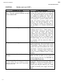
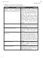
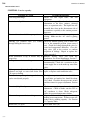
List Of Symptoms ............................................................................................................................................................ 8-1
Machine Won’t Run ........................................................................................................................................................ 8-2, 8-3
Freeze-Up Due To Extended Freezing Period ................................................................................................................. 8-4
Freeze-Up Due To Ice Failing To Discharge ................................................................................................................... 8-5
Low Ice Capacity ............................................................................................................................................................. 8-6
Low Compressor Oil Level .............................................................................................................................................. 8-7
Poor Ice Quality ............................................................................................................................................................... 8-8
High Head Pressure (Water Cooled)................................................................................................................................ 8-9
High Head Pressure (Air-Cooled).................................................................................................................................... 8-10
9. SERVICE OPERATIONS
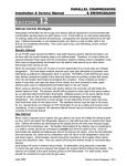
Adjustable Blowdown (For Clearer Ice) FIGURE 9-1 .................................................................................................... 9-1
Automatic Blowdown (Harvest Cycle) ............................................................................................................................ 9-1
Float Valve (Make-Up Water) ......................................................................................................................................... 9-1
Float Switch ..................................................................................................................................................................... 9-2
Hansen Refrigerant Float Switch, FIGURE 9-2............................................................................................................... 9-2
Hand Expansion Valve .................................................................................................................................................... 9-3
Freezer Pressure Switch ................................................................................................................................................... 9-3
Freezer Pressure Switch (Allen-Bradley), FIGURE 9-3 .................................................................................................. 9-3
High/Low Pressure Switch .............................................................................................................................................. 9-4
High/Low Pressure Switch, FIGURE 9-4 ........................................................................................................................ 9-4
Head Pressure .................................................................................................................................................................. 9-4
Water Cooled Units ......................................................................................................................................................... 9-4
Air-Cooled Units ............................................................................................................................................................. 9-5
Water Regulating Valve, FIGURE 9-5A ......................................................................................................................... 9-5
Condenser Fan Switch, FIGURE 9-5B ............................................................................................................................ 9-5
Solenoid Valves ............................................................................................................................................................... 9-5
“X” Solenoid Valve, FIGURE 9-6A & 9-6B................................................................................................................... 9-6
“D” Solenoid Valve, FIGURE 9-7A................................................................................................................................ 9-7
“A” Solenoid Valve, FIGURE 9-7B ................................................................................................................................ 9-7
Oil Separator .................................................................................................................................................................... 9-8
Oil Separator, FIGURE 9-8 ............................................................................................................................................. 9-8
Compressor Crankcase Heater ......................................................................................................................................... 9-8
Copeland Discus Compressor, FIGURE 9-9 ................................................................................................................... 9-8
Compressor Motor Protection, Electronic ....................................................................................................................... 9-9
05TA Service Manual
iv
TABLE OF CONTENTS
Page No
9. SERVICE OPERATIONS (Cont.)
High Potential Testing .................................................................................................................................................... 9-10
Field Troubleshooting...................................................................................................................................................... 9-11
Sentronic Oil Pressure Safety Control FIGURE 9-11...................................................................................................... 9-12
Sentronic Oil Pressure Sensor ......................................................................................................................................... 9-13
Sentronic Oil Pressure Module ........................................................................................................................................ 9-13
CoreSense Protection Module ......................................................................................................................................... 9-13
CoreSense Protection Faults and wiring FIGURE 9-11A................................................................................................ 9-14
Circulating Water Pump Motor ....................................................................................................................................... 9-15
Water Pump, FIGURE 9-12............................................................................................................................................. 9-15
Cutter Gear Reducer ........................................................................................................................................................ 9-15
Gear Reducer, FIGURE 9-13 ........................................................................................................................................... 9-15
Thawing Timer, FIGURE 9-14A ..................................................................................................................................... 9-16
Thawing Timer Wiring, FIGURE 9-14B ......................................................................................................................... 9-16
Condenser Cleaning ......................................................................................................................................................... 9-17
Air-Cooled Condenser ..................................................................................................................................................... 9-17
Pump Down ..................................................................................................................................................................... 9-17
Removal Of Refrigerant From Machine .......................................................................................................................... 9-18
Refrigerant Leaks ............................................................................................................................................................. 9-18
Non-Condensable Gases .................................................................................................................................................. 9-18
Compressor Motor Burnout ............................................................................................................................................. 9-19
Capacity Control Valve (Compressor Unloader) ............................................................................................................. 9-20
Copeland Compressor Unloader Valve, FIGURE 9-15 ................................................................................................... 9-20
Loaded Operation (Freeze Period) ................................................................................................................................... 9-20
Unloaded Operation (During Thaw Only) ....................................................................................................................... 9-20
Cutter Motor .................................................................................................................................................................... 9-21
Cutter Gear Reducer ........................................................................................................................................................ 9-21
Water Tank Removal ....................................................................................................................................................... 9-22
Cutter & Bearing Removal/Installation ........................................................................................................................... 9-22
Cutter Assembly, FIGURE 9-16 ...................................................................................................................................... 9-23
Cutter Drive Parts, FIGURE 9-17.................................................................................................................................... 9-23
Cutter Parts (Cylinder Ice), FIGURE 9-18A.................................................................................................................... 9-24
Cutter Parts (Crushed Ice), FIGURE 9-18B .................................................................................................................... 9-25
Crushed Ice Production ................................................................................................................................................... 9-25
Defrost Pressure Switch (DPS), FIGURE 9-19 ............................................................................................................... 9-26
Pressure Relief Valves ..................................................................................................................................................... 9-26
Technical Service Bulletin: Water Conditioning ............................................................................................................. 9-27
10. OPTIONS AND ACCESSORIES
Power Monitor, FIGURE 10-1 ....................................................................................................................................... 10-2
Power Monitor, Parameters ............................................................................................................................................ 10-3
Programmable Logic Controller (PLC) .......................................................................................................................... 10-4
PLC Input/output Table .................................................................................................................................................. 10-6
05TA Service Manual
v
TABLE OF CONTENTS
Page No
10. OPTIONS AND ACCESSORIES
PLC Wiring ................................................................................................................................................................... 10-7
Operator Interface Information (HMI) ............................................................................................................................. 10-8
HMI Screens .................................................................................................................................................................... 10-9
11. TABLES AND CHARTS
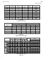
05TA Specifications, 208-230V-3Ph-60Hz, TABLE 11-1 .............................................................................................. 11-2
05TA Specifications, 380V-3Ph-50Hz, TABLE 11-2 ..................................................................................................... 11-3
05TA Capacity Ratings, TABLE 11-3 ............................................................................................................................. 11-4
Condenser Water Usage, TABLE 11-4 ............................................................................................................................ 11-5
Make-up Water Usage (gpm), TABLE 11-5 .................................................................................................................... 11-5
Normal Operating Vitals, TABLE 11-6 ........................................................................................................................... 11-5
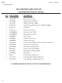
Recommended Spare Parts List ...................................................................................................................................... 11-6
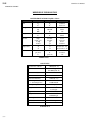
Temperature - Pressure Chart for Common Refrigerants, TABLE 11-7 .......................................................................... 11-7
Conversion Factors: English to Metric, TABLE 11-8 ..................................................................................................... 11-8
Constants, TABLE 11-9 .................................................................................................................................................. 11-8
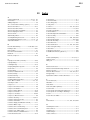
12. INDEX
05TA Service Manual
vi
TABLE OF CONTENTS
05TA Service Manual
1-1
INTRODUCTION
1. Introduction
VOGT ICE, LLC
A Brief History Of Our Company. Henry Vogt Machine Co. was founded as a small machine
shop in Louisville, Kentucky in 1880. In 1938, Vogt built the first Tube-Ice® machine and
revolutionized the ice-making industry. Our first “sized-ice” machine quickly replaced the old canice plants, which required much hard labor and large amounts of floor space for freezing, cutting,
and crushing ice by hand.
Today , VOGT ICE, LLC carries on the tradition as one of the world’s leading producers of icemaking equipment.
Vogt Energy-Saving Tube-Ice Machines Are Cost Effective. Today, Vogt Tube-Ice® machines
enjoy a well-earned reputation as the most energy efficient, dependable ice-making equipment in the
world.
Using as little as one-half to one-third the energy required by competitors’ icemakers, Tube-Ice®
machines produce the same amount of ice--in restaurants, sports arenas, packing plants, and
wholesale operations around the globe--at great savings.
In addition, Tube-Ice® machines are renowned for their long life, giving many customers more than
35 years of dependable service. Ask someone who owns one.
Preview. All the skill in engineering and fabrication that we have learned in over a century of
experience, is reflected in the 05TA model Tube-Ice® machines. Since Vogt introduced Tube-Ice®
machines in 1938, the process of making Tube-Ice® ice has been widely recognized as the most
economical means of production. The machine’s economic and reliable operations have been proven
over and over again, in a network of varied types of installations throughout the world.
Furnished with your machine is the “Certificate Of Test”--the report of operating data that is a record
of the unit’s satisfactory operation on our factory test floor. It is evidence of our desire to deliver to
you “the finest ice-making unit ever made.”
This manual is designed to assist you in the installation, start-up, and maintenance of your unit.
Your Tube-Ice® machine will give you a lifetime of service when you install it, maintain it, and
service it properly.
Please read your manual carefully before attempting installation, operation, or servicing of this
professionally designed piece of equipment.
If you have additional questions, please call your distributor. Also, feel free to phone the factory
direct at (502) 635-3000 OR 1-800-853-8648.
7/19/13
05TA Service Manual
1-2
INTRODUCTION
Important Safety Notice. This information is intended for use by individuals possessing adequate
backgrounds of electrical, refrigeration and mechanical experience. Any attempt to repair major
equipment may result in personal injury and property damage. The manufacturer or seller cannot be
responsible for the interpretation of this information, nor can it assume any liability in connection
with its use.
Special Precautions To Be Observed When Charging Refrigeration Systems. Only technically
qualified persons, experienced and knowledgeable in the handling of refrigerant and operation of
refrigeration systems, should perform the operations described in this manual. All local, federal, and
EPA regulations must be strictly adhered to when handling refrigerants.
If a refrigeration system is being charged from refrigerant cylinders, disconnect each cylinder when
empty or when the system is fully charged. A gage should be installed in the charging line to
indicate refrigerant cylinder pressure. The cylinder may be considered empty of liquid R-22/404A
refrigerant when the gauge pressure is 25 pounds or less, and there is no frost on the cylinder. Close
the refrigerant charging valve and cylinder valve before disconnecting the cylinder. Loosen the
union in the refrigerant charging line--carefully to avoid unnecessary and illegal release of refrigerant
into the atmosphere.
! CAUTION !
Immediately close system charging valve at commencement of defrost or thawing cycle if
refrigerant cylinder is connected. Never leave a refrigerant cylinder connected to system
except during charging operation. Failure to observe either of these precautions can result in
transferring refrigerant from the system to the refrigerant cylinder, over-filling it, and
possibly causing the cylinder to rupture because of pressure from expansion of the liquid
refrigerant.
! CAUTION !
Always store cylinders containing refrigerant in a cool place. They should never be exposed to
temperatures higher than 125°F and should be stored in a manner to prevent abnormal mechanical
shocks.
Also, transferring refrigerant from a refrigeration system into a cylinder can be very dangerous and is
not recommended.
! CAUTION !
It is not recommended that refrigerant be transferred from a refrigeration system directly into
a cylinder. If such a transfer is made, the refrigerant cylinder must be an approved, CLEAN
cylinder--free of any contaminants or foreign materials--and must be connected to an
approved recovery mechanism with a safety shutoff sensor to assure contents do not exceed net
weight specified by cylinder manufacturer or any applicable code requirements.
! CAUTION !
7/19/13
05TA Service Manual
1-3
INTRODUCTION
Safety Symbols & What They Mean. Prior to installation or operation of the Tube-Ice® machine,
please read this manual. Are you familiar with the installation, start-up, and operation of a Tube-Ice®
machine? Before you operate, adjust or service this machine, you should read this manual,
understand the operation of this machine, and be aware of possible dangers.
These Safety Symbols will alert you
when special care is needed.
Please heed.
! DANGER !
Indicates an immediate hazard and that special precautions
are necessary to avoid severe personal injury or death.
! DANGER !
! WARNING !
Indicates a strong possibility of a hazard and that an
unsafe practice could result in severe personal injury.
! WARNING !
! CAUTION !
Means hazards or unsafe practices could result
in personal injury and/or product and/or property damage.
! CAUTION !
7/19/13
05TA Service Manual
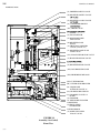
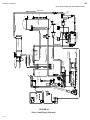
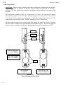
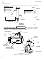
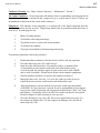
1-4
INTRODUCTION
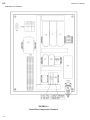
(51) FREEZER SAFETY VALVE
(50) RECEIVER SAFETY VALVE
(59) RECEIVER ACCESS VALVE
(32) CONDENSER SERVICE
(101) CHECK VALVE
VALVE
(22) FLOAT SWITCH
(55) DISCHARGE LINE
STOP VALVE
(30) RECEIVER GAGE
GLASS
(18) THAW GAS SOLENOID
VALVE (VALVE "D")
(31) RECEIVER GAGE GLASS
STOP VALVE
(22A) FLOAT SWITCH STOP VALVE
(17) HAND EXPANSION VALVE
(44) RECEIVER DRAIN VALVE
(1PG) LOW PRESSURE GAGE
(2PG) HIGH PRESSURE GAGE
(5M) CUTTER MOTOR
(5R) CUTTER GEAR REDUCER
(20) LIQUID LINE
SOLENOID VALVE "A"
(94) OIL PRESSURE SWITCH
(28) CHARGING VALVE 1/4"
FLARE
(43) STRAINER
1/2" MPT MAKE UP WATER
CONNECTION
(6) CIRCULATING
WATER PUMP
ICE DISCHARGE
(12) MAKE-UP WATER
FLOAT VALVE
`
7/19/13
FIGURE 1-1
Assembly (Air-Cooled)
Front View
05TA Service Manual
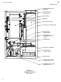
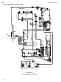
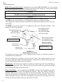
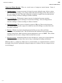
1-5
INTRODUCTION
(8) WATER DISTRIBUTING
CHAMBER
(91) LIQUID RETURN
STOP VALVE
(15R) RECEIVER
(2) FREEZER
(13) HEAT EXCHANGER
(88) SUCTION ACCUMULATOR
(46) LIQUID LINE
FILTER DRIER
(35) COMPRESSOR
DISCHARGE SERVICE
VALVE
(3) COMPRESSOR
(16) THAWING CHAMBER
(6A) WATER PUMP
CHECK VALVE
(7) WATER TANK
(25) WATER TANK DRAIN
CONNECTION 1" FPT
(34) COMPRESSOR SUCTION
SERVICE VALVE
FIGURE 1-2
Assembly (Air-Cooled)
Rear View
7/19/13
05TA Service Manual
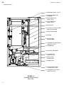
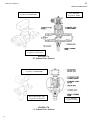
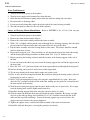
1-6
INTRODUCTION
(55) DISCHARGE LINE
STOP VALVE
(18S) DEFROST PRESSURE
SWITCH
(53) COLD WEATHER
SOLENOID VALVE
("X" VALVE)
(14) OIL SEPARATOR
(41A) CONDENSER PRESSURE
CONTROL SWITCH
(48) COMPRESSOR
DISCHARGE MUFFLER
(58) LIQUID OUTLET STOP
VALVE ("KING" VALVE)
(4PS) DUAL HIGH/LOW
PRESSURE SWITCH
FIGURE 1-3
Assembly (Air-Cooled)
Right
Side View
7/19/13
05TA Service Manual
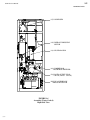
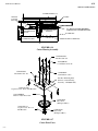
1-7
INTRODUCTION
(23) CONDENSER WATER INLET
(52) CONDENSER SAFETY VALVE
(41) CONDENSER WATER
REGULATOR
(24) CONDENSER WATER
OUTLET
(50) RECEIVER SAFETY VALVE
5/8" FLARE
(59) RECEIVER ACCESS VALVE
1/4" FLARE
(15) CONDENSER
(22A) FLOAT SWITCH STOP VALVE
(90) THAWING GAS STOP
VALVE
(22) FLOAT SWITCH
(30) RECEIVER GAGE
GLASS
(18) THAW GAS SOLENOID
VALVE "D"
(31) RECEIVER GAGE GLASS
STOP VALVE
(17) HAND EXPANSION VALVE
(22A) FLOAT SWITCH STOP VALVE
(1) CONTROL PANEL
(1PG) LOW PRESSURE GAGE
(2PG) HIGH PRESSURE GAGE
(44) RECEIVER DRAIN VALVE
(5M) CUTTER MOTOR
(5R) CUTTER GEAR REDUCER
(94) OIL PRESSURE SWITCH
(28) CHARGING VALVE 1/4"
FLARE
(20) LIQUID LINE
SOLENOID VALVE "A"
(43) STRAINER
1/2" MPT MAKE UP WATER
CONNECTION
(12) MAKE-UP WATER
FLOAT VALVE
FIGURE 1-4
Assembly (Water Cooled)
Front View
7/19/13
05TA Service Manual
1-8
INTRODUCTION
(51) FREEZER SAFETY VALVE
(8) WATER DISTRIBUTOR
CHAMBER
(55) DISCHARGE LINE
STOP VALVE
(91) LIQUID RETURN
STOP VALVE
(15R) RECEIVER
(88) SUCTION ACCUMULATOR/
HEAT EXCHANGER
(13) HEAT EXCHANGER
(2) FREEZER
(46) LIQUID LINE
FILTER DRIER
(35) COMPRESSOR DISCHARGE
SERVICE VALVE
(3) COMPRESSOR
(16) THAWING CHAMBER
(6A) WATER PUMP
CHECK VALVE
(6) CIRCULATING
WATER PUMP
(7) WATER TANK
(25) WATER TANK DRAIN
CONNECTION 1" FPT
(34) COMPRESSOR SUCTION
SERVICE VALVE
FIGURE 1-5
Assembly (Water Cooled)
Rear View
7/19/13
05TA Service Manual
1-9
INTRODUCTION
(15) CONDENSER
(18S) DEFROST PRESSURE
SWITCH
(14) OIL SEPARATOR
(48) COMPRESSOR
DISCHARGE MUFFLER
(58) LIQUID OUTLET STOP
VALVE ("KING" VALVE)
(4PS) DUAL HIGH/LOW
PRESSURE SWITCH
FIGURE 1-6
Assembly (Water Cooled)
Right Side View
7/19/13
1-10
INTRODUCTION
7/19/13
05TA Service Manual
05TA Service Manual
2-1
RECEIPT OF YOUR TUBE-ICE MACHINE
2. Receipt Of Your Tube-Ice Machine
! WARNING !
Only service personnel experienced in refrigeration and qualified
to work with high voltage electrical equipment should be allowed
to install or work on this Tube-Ice® machine.
! WARNING !
Inspection As soon as you receive your machine, inspect it for any damage. If damage is suspected,
note it on the shipper’s papers (i.e., the trucker’s Bill of Lading). Immediately make a separate
written request for inspection by the freight line’s agent. Any repair work or alteration to the
machine without the permission of the Vogt Ice®, LLC can void the machine’s warranty.
The machine was shipped with a full charge of refrigerant stored in the receiver. Visually check all
lines for mechanical damage. If a leak is suspected, check all joints with a Halogen Leak Detector.
All leaks should be reported to the Vogt Ice® LLC to obtain authorization for repair.
! CAUTION !
The approximate weight of the machine is 2450 pounds. Always use
equipment with adequate load carrying capacity.
! CAUTION !
The machine frame has lifting lugs at each corner in the top for eyebolts and hooks to be used for
lifting purposes if desired. Lifting lugs should be used whenever possible.
! CAUTION !
The Tube-Ice® machine is top heavy.
Secure to avoid tipping.
! CAUTION !
If a forklift is used, make sure its capacity is sufficient. The forks must be wide enough apart to
prevent tipping sideways and must extend beyond the extremities of the frame base structure. The
machine needs to be bound in place to prevent tipping.
Safety Valves Safety pressure relief valves are an integral part of the packaged Tube-Ice® machine.
One is located in the low-side of the system on the freezer, and one is in the high side of the system
on the receiver and one is on the condenser. Vent each of the pressure relief valves to the
atmosphere in such a manner as to comply with local and national codes.
Machine Room The machine must be located inside a suitable building and must not be subjected to
ambient temperatures below 50°F (10°C) or above 110°F (43.3°C). Heat from other sources
(sunlight, furnaces, condenser, etc.) and unusual air current may affect the operation of the machine
and should be avoided. The electrical components of the Tube-Ice® machine are rated NEMA 1.
Therefore, the machine should not be located in a hazardous area or sprayed with water. The
machine should be installed on a drainable condensate drip pan or in an area where water will not
stand but will readily drain away from the machine. See Space Diagram for clearances and utility
connections, FIGURES 3-2A and 3-2B.
7/19/13
05TA Service Manual
2-2
RECEIPT OF YOUR TUBE-ICE MACHINE
Storage (prior to installation or start-up). The machine must not be stored or installed in an area
that may reach temperatures 115°F (46.1°C) or above.
! CAUTION !
This equipment contains HCFC-22 or HFC-404a refrigerant under pressure.
Do not store in an area exposed to temperatures above 115°°F (46°°C)
or in direct sun at temperatures above 105°°F (40°°C).
! CAUTION !
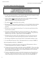
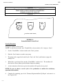
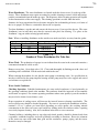
The machine nameplate is located on the front of the control panel. The model number and machine
description are located in the top left hand corner. The following figure can be used to verify that the
correct model has been received.
Nominal Capacity
"02K" - 2000 lbs/day
"03K" - 3000 lbs/day
"04K" - 4000lbs/day
"03T" - 3 tons/day
"05T" - 5 tons/day
"10T" - 10 tons/day
"25T" - 25 tons/day
"50T" - 50 tons/day
"80T" - 80 tons/day
XXXX – XXXX – XXXX – XXX
("K" = 1000's lbs/day, "T" = tons/day)
(Consult Specifications for Actual Capacity)
Basic Configuration
"P" - Package
"L" - Low-side
"H" - High-side
Tube Size (in 1/4's of an inch)
"4" - 1"
"5" - 1 1/4"
"6" - 1 1/2"
"8" - 2"
Model Variation
A number assigned to indicate major
variations within any one family series.
Refrigerant
"F" - R-22
"A" - Ammonia
"H" - R-404a
Electrical Codes
"26" - 208/230-3-60
"46" - 460-3-60
"56" - 575-3-60
"25" - 200-3-50
"45" - 400-3-50
"21" - 230-1-60
Type of Ice
"B" - Cylinder
"K" - Crushed
"D" - Dual Ice (Cru & Cyl)
"L" - 1 1/2" Long Cylinder
"X"- 2” Long Cylinder
Condenser Type
"AC" - Air Cooled
"WC" - Water Cooled
"HP" - High Pressure Water Cooled
"SW" - Sea Water
"NC" - No Condenser
Product Variation Codes (An alphanumeric designator assigned to specific variations.)
"000 or Blank" – Standard Product
If unsure of the product code shown on your machine please consult the factory.
Figure 2-1
Vogt Model Nomenclature
7/19/13
05TA Service Manual
3-1
INSTALLING YOUR TUBE-ICE® MACHINE
3. Installing Your Tube-Ice® Machine
! WARNING !
Only service personnel experienced and certified in refrigeration and qualified to work
with high voltage electrical equipment should be allowed to install or work
on this Tube-Ice® machine.
! WARNING !
Important Notice.
To activate the machine warranty, the Product Registration Form MUST be
completed and returned to the factory promptly after the official start-up.
Product Registration Form is located in the Owners Packet or can be found
online at www.vogtice.com/registration.htm.
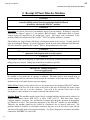
Piping and Drain Connections
Figure 3-2A (Air Cooled) and 3-2B (Water Cooled) show locations and sizes for all connections.
! CAUTION !
External shut-off valves must be provided in the water inlet lines.
The minimum inlet water pressure for satisfactory operation of the machine is 30 psig.
The maximum allowable pressure is 100 psig.
! CAUTION !
Make-up
Water In
1/2” MPT
Water Tank
Drain*
1” FPT
Condenser
Water In
1 1/4” FPT
Condenser
Water Out*
1 1/4” FPT
TABLE 3-1
Water Supply and Drain Sizes
∗ The condenser water outlet and water tank drain connections must be extended separately to an
open drain or sump, arranged for visible discharge. Do not trap the water tank drain line, as
this will interfere with the operation of the automatic blowdown system.
! CAUTION !
These lines must NOT be connected into a pressure tight common header
due to the possibility that warm condenser water may back up into the water tank.
The condenser water outlet MUST be piped separately to the drain.
! CAUTION !
Note: Due to variations in water quality by geographic location, water filtering or treatment may be
required to reduce maintenance and inhibit hardness buildup on machine components (tubes, valves).
Consult your local water treatment company for recommendations and equipment.
3/11/14
05TA Service Manual
3-2
INSTALLING YOUR TUBE-ICE® MACHINE
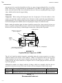
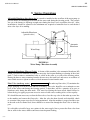
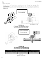
Water-Cooled Connections
Connect water supply to the water regulator valve on condenser water inlet connection (bottom
connection on condenser). Connect the condenser water out line to the top connection on the
condenser.
(24)1 1/4” FPT
Condenser
Water Outlet
(23) 1 1/4” FPT
Condenser Water
Inlet
FIGURE 3-1
Water Cooled Condenser Connections
Cooling Tower.
For water cooled machines only. When selecting a cooling tower, careful attention must be given
to operating wet bulb conditions. It is advisable to check with your local cooling tower distributor
for their recommendations based on actual operating conditions in your area. An average wet-bulb
of 78°F is typical in the U.S. but many localities have design wet-bulbs as low as 72°F or as high as
82°F.
The cooling tower water pump must be capable of delivering the required volume of water through
the condenser. Due to cooling tower location and pressure drop through water lines and water
regulating valves, the pump must be sized for each installation. Refer to TABLE 11-1 for condenser
water requirements. The water piping for the cooling tower and the installation of the pump must be
in accordance with the manufacturer’s instructions.
Proper water treatment for the prevention of mineral and foreign matter accumulation in the
condenser or cooling tower is recommended. A water analysis should be obtained to determine the
proper chemicals to use.
7/19/13
7/19/13
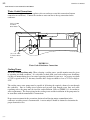
FIGURE 3-2A
Connections and Space Diagram (Air Cooled Machine)
12 5/8"
5 7/8"
13"
LEFT SIDE VIEW
10"
1/2" MPT MAKE-UP
WATER IN
13 3/8"
4"
40" MINIMUM CLEARANCE
FOR WATER TANK ACCESS
ICE DISCHARGE
PROVIDE
SUFFICIENT
SPACE
30" MINIMUM CLEARANCE
FOR CONDENSER CLEANING
LIQUID RETURN LINE
ROTA-LOCK TEFLON FIBER SEAL
PART# 12A-2600T01
ROTA-LOCK FIELD CONNECTOR
PART#12A-2396A0501
1-1/8" IDS X 1-1/4 - 12 THREADS (F)
27 7/8"
FRONT VIEW
1" FPT DRAIN
(REAR OF UNIT)
60"
40" MINIMUM CLEARANCE
FOR COMPRESSOR ACCESS
1/2" MPT
MAKE-UP
WATER IN
RIGHT SIDE VIEW
12" MINIMUM CLEARANCE FOR
INSTALLATION AND ACCESS
DISCHARGE LINE
(SHOWN FROM TOP OF ICE MACHINE)
ROTA-LOCK TEFLON FIBER SEAL
PART# 12A-2600T03
ROTA-LOCK FIELD CONNECTOR
PART#12A-2396A0601
1-3/8" IDS X 1-3/4 - 12 THREADS (F)
28 3/8"
FIELD ATTACHMENT
AIR COOLED CONDENSER TUBING
85"
05TA Service Manual
3-3
INSTALLING YOUR TUBE-ICE® MACHINE
7/19/13
12 5/8"
5 7/8"
FIGURE 3-2B
Connections and Space Diagram (Water Cooled Machine)
13"
LEFT SIDE VIEW
10"
32"
6 5/8"
1/2" MPT MAKE-UP
WATER IN
13 3/8"
40" MINIMUM CLEARANCE
FOR WATER TANK ACCESS
ICE DISCHARGE
PROVIDE
SUFFICIENT
SPACE
30" MINIMUM CLEARANCE
FOR CONDENSER CLEANING
1 1/4" FPT
CONDENSER
WATER OUT
1 1/4" FPT
CONDENSER
WATER IN
11 3/4"
7 1/2"
27 7/8"
FRONT VIEW
1" FPT DRAIN
(REAR OF UNIT)
60"
28 3/8"
40" MINIMUM CLEARANCE
FOR COMPRESSOR ACCESS
1/2" MPT
MAKE-UP
WATER IN
RIGHT SIDE VIEW
12" MINIMUM CLEARANCE FOR
INSTALLATION AND ACCESS
85"
3-4
05TA Service Manual
INSTALLING YOUR TUBE-ICE® MACHINE
05TA Service Manual
3-5
INSTALLING YOUR TUBE-ICE® MACHINE
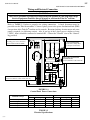
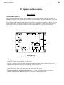
Wiring and Electrical Connection
! WARNING !
Only service personnel experienced in refrigeration and qualified to work with high voltage
electrical equipment should be allowed to install or work on the Tube-Ice® machine.
! WARNING !
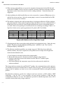
Refer to TABLE 3-2 below to properly size wiring connections. A fused disconnect must be
provided near the Tube-Ice® machine. Connect 3 phase power to the power distribution block (PDB)
for operation of the Tube-Ice® machine and its controls. Rotation checking of cutter motor and water
pump is required (see following section). Also, if one leg of the 3 phase power is higher or lower
(“Wild”), then it should be connected to terminal #L2. Connect the “Ground” wire to the “Ground”
lug provided.
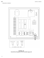
MAIN MACHINE POWER
Incoming power to be connected to
Power Distribution Block (PDB)
AUX CONNECTIONS
Cutter Motor, Pump Motor
& Compressor Interlocks
AIR COOLED CONDENSER
CONNTECTIONS
Power for Fan Motors (B7, B8 & B9)
AIR COOLED CONDENSER CONNTECTIONS
Power for Condenser control circuit (11 & 22)
FIGURE 3-3
Control Panel Power Connections
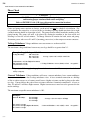
Standard Voltages
208/230, 3ph, 60 Hz
460, 3ph, 60 Hz
220, 3ph, 50 Hz
400, 3ph, 50 Hz
F.L.A.
66.9
32.7
67.5
33.2
Water Cooled
Min. Ampacity Max. Fuse
81.8
145
39.9
70
82.4
145
40.4
70
TABLE 3-2
Electrical Specifications
7/19/13
F.L.A.
80.9
39.7
81.5
40.2
Air Cooled
Min. Ampacity
95.8
46.9
95.8
47.4
Max. Fuse
160
80
160
80
05TA Service Manual
3-6
INSTALLING YOUR TUBE-ICE® MACHINE
Phase Check
! CAUTION !
DO NOT attempt to start machine without priming pump
and insuring proper rotation of both cutter and pump.
Refer to FIGURE 3-2A & 3-2B (space diagram) for connection locations.
! CAUTION !
Cutter and pump motor rotation are factory synchronized but must be checked at installation. For
ice production, the cutter disc, as viewed at the ice discharge opening should turn from left to right
(crushed rotation should be from right to left). The pump rotation should match the marking on the
pump housing. The pump will need to be primed by starting the machine in the clean mode and
allowing it to run for several minutes. To change direction of rotation for both, cutter and pump,
disconnect power and reverse L1 and L3 (incoming power wires) at the compressor motor contactor.
Voltage Unbalance Voltage unbalance can cause motors to overheat and fail.
The maximum voltage unbalance between any two legs should be no greater than 2%.
Example: Supply Voltage = 230-3-60
Voltage Readings:
AB = 220 Volts
BC = 225 Volts
AC = 227 Volts
Average = (220 + 225 + 227)/3 = 224 Volts
(AB) 224-220 = 4 Volts (Highest Deviation)
(BC) 225-224 = 1 Volts
% Voltage Unbalance = 100 x (4/224) = 1.78% “Acceptable”
(AC) 227-224 = 3 Volts
Important: If the supply voltage phase unbalance is more the 2%, contact your local electric
utility company.
Current Unbalance Voltage unbalance will cause a current unbalance, but a current unbalance
does not necessarily mean that a voltage unbalance exists. A loose terminal connection or a buildup
of dirt or carbon on one set of contacts would cause a higher resistance on that leg than on the other
two legs. Current follows the path of least resistance, therefore if terminal connection L1 is loose or
dirty, L2 and/or L3 will have higher current. Higher current causes more heat to be generated in the
motor windings.
The maximum acceptable current unbalance is 10%.
Example:
Current Readings:
L1 = 96 Amps
L2 = 91 Amps
L3 = 98 Amps
(L1) 96-95 = 1 Amps
(L2) 95-91 = 4 Amps (Highest Deviation)
(L3) 98-95 = 3 Amps
7/19/13
Average = (96 + 91 + 98)/3 = 95Amps
% Current Unbalance = 100 x (4/95) = 4.2% “Acceptable”
05TA Service Manual
3-7
INSTALLING YOUR TUBE-ICE® MACHINE
Air-Cooled Condenser Installation Instructions
! WARNING !
These installation guidelines must be followed to obtain
reliable operation from air cooled ice machines.
IF THESE GUIDELINES ARE NOT FOLLOWED THE
COMPRESSOR WARRANTY WILL NOT BE HONORED.
! WARNING !
1. Use only Vogt approved condensers. Any exceptions to this policy must be obtained in writing
from Vogt prior to installation and operation of the ice machine.
2. Outdoor condensers must be installed with vertical air flow. Indoor condensers used for heat
recovery may be installed with either horizontal or vertical air flow.
NOTE: Condenser must be ordered for horizontal air flow.
3. The condenser must be mounted above the ice machine.
4. Horizontal runs in the liquid return line should slope 1/4” per foot with liquid refrigerant draining
freely in the direction of normal operating flow (back to the ice machine) with no traps in the
liquid line.
5. Horizontal runs in the discharge line should slope 1/4” per foot in the normal direction of flow
(away from the ice machine).
6. Traps must be installed in discharge lines at the base of all vertical risers. There should be no
intentional traps in liquid lines. Trap volume should be kept to a minimum. Long vertical rises
should have traps every 20 feet. Typical details are shown in FIGURE 3-6.
7. Flooding head pressure controls such as Alco Headmaster are not to be used since they cause
excessive subcooling of the returned liquid refrigerant and interfere with reliable ice harvest.
8. The discharge and liquid lines must be insulated with 1/2” thick Armaflex insulation or equal.
9. Use only ACR grade copper pipe, Type L. Recommended line sizes are shown in TABLE 3-5.
10. For field attachment instructions, see FIGURE 3-5.
11. Distance between ice machine and condenser must not exceed 150 equivalent feet. Refer to
Condenser Equivalent Line Size worksheet (see TABLE 3-5 ).
12. Condensers must be provided with a cold weather valve kit per FIGURE 3-5. These valves allow
one-half of the condenser to be disabled in cold weather. Running the ice machine with one-half
of the condenser in cold weather makes it easier to maintain minimum necessary condensing
pressure particularly in windy conditions.
13. Condensers with multiple fans must be provided with a thermostat to turn off unneeded fans in
cold weather. Turning off unneeded fans reduces on-off cycling of the fan(s) and allows for a
steadier condensing pressure and more consistent warm gas for ice harvesting FIGURE 3-7.
3/14/14
05TA Service Manual
3-8
INSTALLING YOUR TUBE-ICE® MACHINE
14. When extreme cold conditions are expected or encountered (temperatures below 0°F and wind
greater than 15 MPH), it may be necessary to install a protective enclosure around the condenser.
Apparatuses such as louvers may also be used for varying conditions. Contact the factory for
suggestions.
15. After installation, the field installed lines are to be evacuated to a vacuum of 500 microns or less
and held for at least one hour. After the vacuum pump is removed, vacuum should hold at 500
microns or less for at least 5 minutes.
16. The machine is shipped with a full operating charge of refrigerant sufficient to fill the condenser
and connecting lines. If the condenser piping is longer than 50 feet (one way), additional R-22 or
R-404a may need to be added to retain enough refrigerant in the receiver for thawing purposes
(see table. Refer to the operating level mark on the receiver and charge accordingly. Each 1” of
liquid level in the receiver equals approximately 5.5 pounds of R-22 or R-404a.
Liquid Line Size
1/2”
5/8”
7/8”
1-1/8”
75 ft.
none
none
none
none
100 ft.
125 ft.
None
None
2
4
4
8
6
12
TABLE 3-3
Pounds of R-22/404A to Add vs. Liquid Line Length
150 ft.
2
6
12
18
17. All piping must be done in accordance with applicable local and national codes. Such codes may
include “The Safety Code For Mechanical Refrigeration” (ANSI B9.1) and “The Code For
Refrigerant Piping” (ANSI B31.5).
18. The following installation guidelines are strongly suggested. While they do not affect the
machine warranty, they may be required for safe operation and to comply with all applicable
electrical and mechanical codes:
a. Local electrical code must be checked for wiring method.
b. The installer must provide a disconnect switch(s) adjacent to the condenser.
c. Electrical connections between the condenser and the Tube-Ice® machine require
minimum 12 ga. wire.
d. All electrical fittings and components exposed to the weather must be suitable for
outdoor installation.
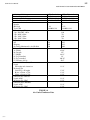
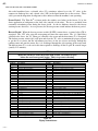
The design total heat rejection for each Tube-Ice® machine, the recommended air-cooled condenser,
and condenser physical and electrical data are shown on the next page. Specified energy efficiency
ratings of the ice machines are based on use of the recommended condenser and approved piping
practices.
Recommended condensers provide the indicated total heat rejection at 90°F ambient, 100°F
condensing. Vogt Ice, LLC is not responsible for head pressure problems if other than the
recommended condensers are used. For continuous operation at ambient temperature above 105°F,
consult the factory about using a larger condenser.
7/19/13
05TA Service Manual
3-9
INSTALLING YOUR TUBE-ICE® MACHINE
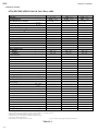
Ice Machine Model
Electrical Frequency, Hz.
Recommended Condenser
Total Heat Rejection (BTU/hr)
Fans:
Number
HP, Each
Total CFM
Full Load Amps (FLA):
3 ph., 208/230V., 60 hz.
3 ph., 460V., 60 hz.
3 ph., 190V., 50 hz.
3 ph., 380V., 50 hz.
Weight, lbs.:
Net
Shipping
Operating (Maximum flooded) R-404a
Condenser Dimensions, inches
A (Width)
B (Length)
C (Height)
D (Leg centerline)
E (Leg centerline)
F (Clearance below)
Recommended Line Sizes, OD
Liquid
All lengths and orientations
Discharge Gas
Vertical Up, all lengths
Horiz. or Down, < 75 ft.
Horiz. or Down > 75 ft.
Connections at Condenser:
Liquid (ODC)
Discharge Gas (ODC)
Connections at Ice Machine:
Liquid (ODC)
Discharge Gas (ODC)
05TA (Standard)
60/50
BNHS02A015(8)
192,000 / 176,600
05TA (High Ambient)
60/50
BNHS02A015(12)
229,500 / 211,100
2
1 1/2
19,800/18,216
2
1 1/2
19,800/18,216
14.0
7.0
14.0
7.0
625
805
680
TABLE 3-4
Air-Cooled Condenser Data
3/21/14
635
815
690
45.46”
127”
49.15”
38”
106.15”
20.5”
1 1/8”
1 3/8”
1 3/8”
1 5/8”
1 1/8”
1 5/8”
1 1/8”
1 3/8”
05TA Service Manual
3-10
INSTALLING YOUR TUBE-ICE® MACHINE
FIGURE 3-4
Condenser Dimensions
Machine
Bohn Part #
Vogt Part #
Coil Split
P118 (Standard)
BNHS02A015(8)
12A2115B09
50/25/25
P118 (High Ambient)
BNHS02A015(12)
12A2115B10
50/25/25
Note: Condensers listed above are 200/208/230V, 50/60hz. 400/460V, 50/60hz available
7/19/13
05TA Service Manual
3-11
INSTALLING YOUR TUBE-ICE® MACHINE
FIGURE 3-5
Condenser Field Piping (Cold Weather Valve Kit)
7/19/13
05TA Service Manual
3-12
INSTALLING YOUR TUBE-ICE® MACHINE
CONDENSER EQUIVALENT LINE SIZE WORKSHEET
Discharge Gas Line O.D. ___________________
Fitting Type
Globe Valve (open)
Angle Valve (open)
90° Elbow
45° Elbow
Tee
Number Used
Factor
Total
Feet of Straight Copper Used
Total Fitting Factor
Total Equivalent Feet
Copper Tubing Type “L”
Globe valve (open)
Angle valve (open)
90o Elbow
45o Elbow
Tee (90° turn through)
Tee (straight through)
1 1/8” O.D.
28
15
3
1.5
6
2
1 3/8” O.D.
36
18
4
2
8
2.5
1 5/8” O.D.
42
21
4
2
9
2.8
2 1/8” O.D.
57
28
5
2.5
12
3.5
TABLE 3-5
Equivalent Feet Due To Friction
FIGURE 3-6
Minimum Traps For Discharge Lines
*Note: Each recommended line size is based on use of Type “L” copper tubing at a maximum
equivalent distance of 150 feet. See TABLE 3-5 for equivalent feet of valves and fittings.
7/19/13
05TA Service Manual
3-13
INSTALLING YOUR TUBE-ICE® MACHINE
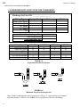
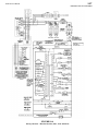
Air-Cooled Condenser Wiring
FIGURE 3-7
Wiring For BOHN BNHS02A015(8)/BNHS02A015(12) with Cold Weather Valve and
Two Fan, 50/25/25 Condenser Split
4/15/14
05TA Service Manual
3-14
INSTALLING YOUR TUBE-ICE® MACHINE
Air-Cooled Connections (See FIGURE 3-2A for connection sizes)
Follow these procedures to make a tight joint:
1. Silver solder or braze condenser tubing ends to the female Rota-lock connectors.
2. Remove dust caps if used, making sure that component plastic seals are intact.
3. Wipe off connector and spud threaded surfaces with a clean cloth to prevent the inclusion of dirt
or any foreign material in the system.
4. Connector coupling nut should be screwed onto Rota-lock spud using the proper amount of torque.
Spud Size
7/8”
1 1/8”
1 3/8”
Amount of Torque
50-60 FT LBS
80-100 FT LBS
100-110 FT LBS
TABLE 3-6
Rota-lock Connector Torque Ratings
Pressure Relief Valves Pressure relief valves are installed on the freezer, receiver and the
water cooled condenser. These valves are designed to vent in emergency conditions. This ensures
vessel internal pressure does not exceed maximum allowable pressures.
Vent the relief valve outlet to a safe outdoor location in the approved manner away from people and
building openings. Vent line piping must have drain line at low point to drain conde
nsate from line per ASME Boiler and Pressure Code, Section VIII, Division 1.
PRESSURE RELIEF VALVES MUST BE REPLACED AFTER 5 YEARS OF SERVICE.
BEFORE REPLACING RELIEF VALVE, REVIEW REQUIREMENTS PER CURRENT
LOCAL AND NATIONAL CODE.
VALVE REPLACEMENT SHOULD BE MADE BY PROPERLY TRAINED PERSONNEL ONLY.
NOTE: IF RELIEF VALVE DISCHARGES, VALVE MUST BE REPLACED AFTER DISCHARGING
BECAUSE SETTING OR SEAT TIGHTNESS MAY BE ALTERED.
CONTACT VOGT ICE PARTS DEPARTMENT FOR REPLACEMENT VALVES.
PHONE: 502-635-3000
3/7/14
05TA Service Manual
3-15
INSTALLING YOUR TUBE-ICE® MACHINE
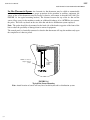
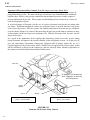
Ice Bin Thermostat Sensor An electronic ice bin thermostat may be added to automatically
cycle machine operation. To assure proper protection for the machine or auxiliary equipment, the
sensor of the ice bin thermostat must be located so that ice will contact it when the bin is full (See
FIGURE 3-8 for typical mounting bracket). The distance between the top of the ice bin and the
sensor allows space for the machine to make an additional discharge of ice AFTER the ice contacts
the probe. This will vary based on the size of the bin and the ice distribution system employed.
Note: The probe should also be mounted on the back side of the bracket, opposite of the front of the
bin to reduce the possibility of damage from ice removal equipment.
The control panel is electrically connected so that the bin thermostat will stop the machine only upon
the completion of a harvest period.
NOTE: Use front of
angle to protect
probe
STAINLESS
STEEL
ANGLE
FIGURE 3-8
Typical Bin Sensor Mounting
Note: Actual location of sensor will vary based on bin layout and ice distribution system.
3/7/14
05TA Service Manual
3-16
INSTALLING YOUR TUBE-ICE® MACHINE
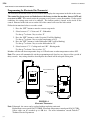
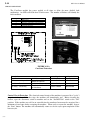
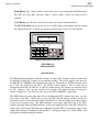
Programming the Electronic Bin Thermostat
The electronic bin thermostat has an LCD readout that displays the temperature in the bin at the sensor.
The control has been preset and locked out at the factory to shut the machine down at 38°°F and
to re-start at 40°°F. The control retains the program even if power is cut to the machine. Under special
conditions, the settings may need to be changed. The lockout switch is located on the inside of the
control. Removal of the four screws on the face of the control will reveal the lock-switch.
Follow the instructions below to reset the switch.
1. Press the “SET” button to enter the sensors setup mode
2. Select between “C”- Celsius and “F” - Fahrenheit
Use the up ↑ or down ↓ key to select “F”
3. Press the “SET” button to set the Set point (S1 will be blinking)
Use the up ↑ or down ↓ key to set the temperature at 38°F
4. Press the “SET” button to set the Differential (DIF 1 will be blinking)
Use the up ↑ or down ↓ key to set the differential at 2°F
5. Select between “C1”- Cooling mode and “H1” - Heating mode
Use the up ↑ or down ↓ key to select “C1”
Machine will shut off when temperature drops to 38°F and come on when temperature reaches 40°F.
Note: The sensor will automatically exit the programming mode if no keys are depressed for a period of
thirty seconds. Any settings that have been input to the control will be accepted at that point.
DIGITAL TEMPERATURE
READING
SENSOR
SENSOR POWER
CONNECTION
CONTROL CIRCUIT
CONNECTION
FIGURE 3-9
Electronic Thermostat
Note: If damaged, the sensor can be replaced without replacing entire unit.
Replacement sensor part #12A2117G0901. Electronic temperature control part #12A2117G09.
Sensor cable can be extended up to 400 feet. For more information, consult Tube-Ice®
Technical Service Department.
3/7/14
05TA Service Manual
3-17
INSTALLING YOUR TUBE-ICE® MACHINE
! IMPORTANT !
Be sure to follow the wiring schematic and electrical
specification table when incorporating overloads.
This is necessary to provide proper protection
for the Tube-Ice machine and its component parts.
! IMPORTANT !
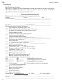
Installation Review: A Checklist. Make a visual check to be sure these steps have been taken
BEFORE continuing.
CHECK: ____ PRIOR TO OPENING VALVES, check all joints for leaks which may have
developed during shipment.
(NOTE: the machine was shipped with a positive pressure of 20-25 PSIG, verify on
the freezer pressure gage.)
CHECK: ____ All refrigerant piping, water supply and drain connections for conformity to
requirements stipulated in this manual and properly connected to inlets and outlets.
CHECK: ____ Electrical supply for proper size of fuses and for compliance to local and national
codes. See the machine nameplate for minimum circuit ampacity and maximum fuse
size.
CHECK: ____ All field installed equipment (augers, conveyors, cooling towers, bin level controls,
etc.) for proper installation.
CHECK: ____The applicable portion of the warranty registration/start-up report for proper
completion.
CHECK: ____ Cutter gear reducer oil level oil should run out of side pipe plug when removed.
CHECK: ____ The water distributors at top of freezer to make sure they are all in position
! CAUTION !
The compressor crankcase heater should be energized for a minimum of
Two (2) hours before attempting to start the compressor.
! CAUTION !
3/14/14
05TA Service Manual
3-18
INSTALLING YOUR TUBE-ICE® MACHINE
BLANK PAGE
3/7/14
05TA Service Manual
4-1
HOW YOUR TUBE-ICE MACHINE WORKS
4.
How Your Tube-Ice® Machine Works
Principle of Operation For a detailed description of the functions of each control panel component,
see Section 6. Operation of the machine is controlled by “Clean/Off/Ice”, “Start” and “Stop”
switches located in the control panel of the freezing unit. Automatic operation can be controlled by
an optional ice bin thermostat which will automatically stop and start the ice maker by the level of
the ice in the storage bin (NOTE: See FIGURE 3-8, “Ice Bin Thermostat Location” for instructions
on installation of the control sensor of the ice bin thermostat(s)). The type ice produced (cylinder or
crushed) is determined by how the machine cutter is set-up (cylinder is standard, crushed or
automatic is optional). The control wiring is arranged so that the unit will stop only upon the
completion of a thawing period whether by action of the “Clean/Off/Ice” switch in the “Off”
position or the ice bin thermostat.
The “Clean/Off/Ice” switch must always be set in the “Ice” position during normal ice-making
operation. It is set in the “Clean” position only when the equipment is to be cleaned as outlined in
the “Cleaning Procedure” (Section 7) and instructions shown on the water tank cover.
If it should become necessary to instantly stop the machine, push the “Stop” button. To restart the
machine, push the “Start” button. The machine will restart in a harvest, to clear out any ice
remaining in the freezer, if stopped during a freeze period.
FIGURES 4-1 & 4-2 illustrate the piping diagram of the refrigerant and water circuits of the TubeIce® machine with numbers for easy reference. Throughout this manual, the numbers you see in
parentheses refer to the numbers in this piping schematic.
The freezer (2) is a shell and tube-type vessel. During the freezing period, water is constantly
recirculated through the vertical tubes of the freezer by a centrifugal pump (6). Make-up water is
maintained by a float valve (12) in the water tank (7). The liquid feed solenoid valve (20),
sometimes referred to as the “A” valve, is open and the thawing gas solenoid valve (18), sometimes
referred to as the “D” valve, is closed.
Refrigerant gas from the top of the freezer (2) passes through the suction accumulator (88), the heat
exchanger (13), and to the compressor (3). Here the cool gas is compressed to a high temperature,
high pressure gas which discharges through the oil separator (14) and into the condenser (15). In the
condenser, heat is removed and the gas is condensed to a high temperature, high-pressure liquid.
The high-pressure liquid goes through the accumulator boil out coil (88) and suction line heat
exchanger (13) where it gives up heat to the suction gas for compressor protection. In addition, this
liquid is subcooled and carried to the receiver (15R). Liquid refrigerant from the receiver flows
through the filter/drier (46), thawing chamber (16), liquid feed solenoid valve (“A” valve) (20) and
hand expansion valve (17) into the freezer. The float switch (22) is wired to the “A” solenoid valve
(20). The float switch energizes and de-energizes the “A” solenoid in response to the level of
refrigerant in the freezer. The cold liquid refrigerant enters the freezer where it absorbs heat from
the circulating water. Cool gas is pulled out of the freezer at the suction outlet thereby completing
the cycle.
The freezing period is completed by action of the freezer pressure switch in the control panel. The
water pump (6) is stopped and solenoid valve “A” (20) is closed. The thawing period then begins.
Solenoid valve “D” (18) is opened, the cutter motor (5M) is started and the harvest (thaw) timer is
activated. Warm gas from the receiver is discharged into the freezer through valve (18), thereby
slightly thawing the outer edge of the ice, which drops on the rotating cutter for sizing. See “Freezer
Period and Harvest Period” for more detailed description of operation.
7/19/2013
05TA Service Manual
4-2
HOW YOUR TUBE-ICE MACHINE WORKS
Air-cooled machines have a solenoid valve (53), sometimes referred to as the “X” valve, in the
compressor discharge line, and a check valve (101) in the liquid return line to the receiver. These
valves prevent the migration of refrigerant to the condenser when the machine is not operating.
Freeze Period. The Tube-Ice® is frozen inside the stainless steel tubes in the freezer (2) by the
direct application of refrigerant to the shell side (outside) of the tubes. The ice is produced from
constantly recirculating water during the freeze period. As the ice thickness increases, the freezer
suction pressure decreases. At a set pressure, the freezer pressure switch initiates the harvest period.
Harvest Period. When the freezer pressure switch (56, FPS) contact closes, a control relay (CR) is
energized. The “CR” relay stops the water pump and starts the cutter motor. The “A” (liquid line)
solenoid valve closes, the “D” (thaw gas) solenoid valve opens and the thaw timer (T) is energized.
The defrost pressure switch (dps) will open and close the “D” valve to maintain the proper pressure
to get the ice to release but not add unnecessary heat. As the ice releases and drops through the
rotating cutter and onto the cutter disc, it is discharged through the side opening of the water tank.
The harvest timer (T) is to be set for the time required to discharge all the ice plus 30 seconds longer
(usually 2 1/2 minutes).
! CAUTION !
Make sure all the ice clears the freezer with at least 30 seconds to spare
before the next freeze period begins. This is to prevent refreezing.
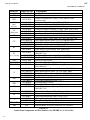
! CAUTION !
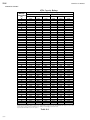
Item No.
1
1PG
2PG
2
3
4PS
5M
5R
6
6A
7
8
12
13
14
15
15R
16
17
18
18S
20
22
22A
23
24
25
28
30
Description
Control Panel
Suction Pressure Gauge
Discharge Pressure Gauge
Freezer
Compressor
Dual High/Low Pressure Switch
Cutter Motor
Gear Reducer
Water Pump
Water Pump Check Valve
Water Tank (includes cutter assembly)
Water Distributing Chamber
Make-Up Water Float Valve
Heat Exchanger
Oil Separator
Condenser
Receiver
Thawing Chamber
Hand Expansion Valve
Thawing Gas Solenoid Valve “D”
Thawing Gas Cycling Pressure Switch “DPS”
Liquid Feed Solenoid Valve “A”
Float Switch
Float Switch Stop Valves
Condenser Water Inlet W/C Machines
Condenser Water Outlet (W/C Machines)
Water Tank Drain Connection (1” FPT)
Refrigerant Charging Valve
Receiver Gage Glass
Item No.
31
32
34
35
37
39
40
41
41A
43
44
46
48
50
51
52
53
55
56
58
59
69
70
88
90
91
94
101
Description
Gage Glass Stop Valve
A/C Condenser Service Connection
Compressor Suction Service Valve
Compressor Discharge Service Valve
Oil Charging/Drain Valve
Water Tank Drain Valve
Automatic Water Tank Blowdown
Condenser Water Regulator (W/C Machines)
Condenser Pressure Control (A/C Machines)
Strainer
Receiver Drain Valve
Filter Drier
Muffler
Receiver Safety Valve
Freezer Safety Valve
Condenser Safety Valve
Cold Weather Solenoid Valve “X” (A/C Machines)
Discharge Line Stop Valve
Freezer/Pressure Switch
Liquid Outlet Valve (King Valve)
Receiver Purge Valve
Freezer Pressure Stop Valve
Oil Return Stop Valve
Accumulator/Heat Exchanger
Thawing Gas Stop Valve
Receiver Liquid Return Stop Valve
Compressor Oil Pressure Safety Control/CoreSense
Check Valve (A/C Machines)
Table 4-1
Piping Nomenclature
7/19/2013
FIGURE 4-1
Water Cooled Piping Schematic
7/19/2013
1PG
56
2PG
1
CONTROL
PANEL
6-PUMP
6A
18S
DPS
16
22A
43
WAT
ER
CIRC
ULA
TING
12
22
5R
17
22A
5M
WATER TANK DRAIN
7-WATER TANK
28
20
2 - FREEZER
69
51
8
23
24
88
39
40
CUTTER
MOTOR
52
13
25-WATER OUT
23A-WATER IN
LIQUID LINE
THAW GAS
LIQUID RETURN
LIQUID RETURN
WATER IN
41
WATER OUT
34
46
37
18
3 - COMPRESSOR
35
4PS
HI-LO
15
CONDENSER
91
90
44
OIL RETURN
70
48
MUFFLER
94
OIL
58
15R
RECEIVER
50
DISCHARGE
14
OIL
SEP.
55
31
30
31
59
05TA Service Manual
4-3
HOW YOUR TUBE-ICE MACHINE WORKS
DISCHARGE
7/19/2013
FIGURE 4-2
Air Cooled Piping Schematic
1PG
56
2PG
1
CONTROL
PANEL
16
22A
43
CIRC
UL
A
T
ING
WAT
ER
6-PUMP
6A
18S
DPS
12
22
5R
17
22A
5M
WATER TANK DRAIN
7-WATER TANK
28
20
2 - FREEZER
69
51
8
88
39
40
CUTTER
MOTOR
32
13
101
25-WATER OUT
23A-WATER IN
34
LIQUID LINE
THAW GAS
LIQUID RETURN
LIQUID RETURN
15
CONDENSER
AIR
FLOW
37
41A
FAN
46
3 - COMPRESSOR
4PS
LO-HI
18
91
35
90
44
OIL RETURN
70
48
MUFFLER
94
OIL
58
15R
RECEIVER
50
DISCHARGE
53
31
30
31
59
DISCHARGE
14
OIL
SEP.
55
4-4
05TA Service Manual
HOW YOUR TUBE-ICE MACHINE WORKS
05TA Service Manual
5-1
START-UP AND OPERATION
5. Start-Up and Operation
Refrigeration System Review. The refrigeration system uses R-22 or R-404a refrigerant, a
compressor, a refrigerant float switch, a flooded evaporator (freezer), and warm gas defrost.
Following the schematic, notice that during the freeze period of the machine’s cycle, the compressed
discharge gas leaves the compressor and goes to the condenser where it is condensed into liquid by
the removal of heat by either air or water passing through the condenser. A reservoir of liquid is
accumulated in the receiver and flows as required, passing through the filter/drier, the thawing
chamber (a lower separate section of the freezer) and the liquid feed solenoid valve (the “A” valve).
The opening of the “A” valve by the float switch during the freeze cycle allows the liquid to be
metered by the hand expansion valve (17). The “A” valve opens and closes in response to the float
switch and refrigerant level in the freezer. Wet refrigerant floods the evaporator and is in contact
with the outside of the ice-making tubes in which water is being circulated. The heat contained in
this water passes through the wall of the tubes, lowering the temperature of the water, causing it to
freeze and form a long tube of ice that adheres to the inside of each of the freezer tubes. The flowing
water keeps the accumulated ice clear by washing separated solids down into the sump area of the
water tank.
The wet suction gas leaves the freezer and any remaining liquid droplets are removed by the
accumulator and suction line heat exchanger. The dry gas enters the compressor and is compressed
then discharged to the condenser completing the cycle.
As the ice is formed in the freezer, the suction pressure steadily reduces until it causes the freezer
pressure switch contacts to close, initiating the harvest period.
During the harvest period, the liquid feed solenoid valve (“A” valve) closes and the thawing gas
solenoid valve (the “D” valve) is open allowing the warm high pressure gas to enter the freezer. This
heat warms the tubes, allowing the ice to release and slide down onto the rotating cutter. This thaw
period lasts approximately 2 1/2 minutes.
Refrigerant Charge. Included with the machine is the required charge (approximately 250 lbs.) of
Refrigerant 22 or 404a, depending on the model, which has been isolated in the receiver (15R).
Before shipment of the machine, the compressor service valves (34), (35), and the stop valves in the
various lines to the condenser and receiver have been closed. These valves are tagged with
instructions that the valves are to be opened prior to start-up of the machine. Before opening these
valves, it is advisable to check all joints for leaks that may have developed during shipment. If no
leaks are present, a positive pressure should show on the suction and discharge pressure gages.
If it should ever become necessary to add refrigerant to the system, charging valve (28) is provided
for this purpose. Through this valve, refrigerant can be added in liquid form. See “Adding
Refrigerant." The compressor crankcase heater must be energized for a minimum of two hours prior
to starting and running the compressor.
7/19/13
05TA Service Manual
5-2
START-UP AND OPERATION
Start-up Checklist. Be sure to complete and return the “Warranty Registration/Start-Up Report”
located at the front of the manual.
_____ 1.
See that water-inlet and outlet connections are attached properly. The
water inlet shutoff valves for the water tank and condenser should be
open. The water level in the water pan should be at a height where the
make-up water float valve will be closed when the machine is idle.
_____ 2.
See that the cutter motor gear reducer is lubricated (see Section 7 “Lubrication”
Cutter gear reducer (5R) for instructions).
_____ 3.
See that compressor crankcase oil level is at proper height of 1/4 to 1/2 of
the sight glass.
NOTE
All valves are tagged with instructions.
NOTE
7/19/13
_____ 4.
Open compressor service valves (34 and 35), the hand-stop valve (90) in the thawing
gas line, the receiver liquid return stop valve (91) in the condenser return line, handstop valve (58) in the liquid line, hand-stop valve (69) to the freezer pressure switch,
top and bottom float switch hand stop valves (22A) and stop valve (70) in the oil
return line. These valves are tagged to indicate that they were closed for shipping
purposes. Gage glass valves (31) on the receiver can be opened for liquid level
observation but should remain closed for unattended operation.
_____ 5.
IMPORTANT! CHECK TO SEE that all stop valves in the various refrigerant lines
are open except charging valves (28 & 44), according to the attached tags.
_____ 6.
Immediately after opening all valves, entire machine should be checked for
refrigerant leaks with electronic leak detector.
_____ 7.
See that “Ice/Off/Clean” Switch (SS) is in the “Ice” position.
_____ 8.
Close exterior disconnect switch to energize crankcase heater and check for
compliance to nameplate.
05TA Service Manual
5-3
START-UP AND OPERATION
! CAUTION !
The crankcase heater should be energized for a MINIMUM of
2 hours and the crankcase must be free of liquid before
attempting to operate the compressor.
! CAUTION !
Off
Clean Ice
Stop
Start/
Manual
Harvest
CONTROL PANEL DOOR)
FIGURE 5-1
Bottom Portion of Control Panel
Start-Up Procedure
Starting the machine in freeze mode:
(NOTE: to start in harvest mode, turn “Clean/Off /Ice selector switch to “Ice” and press “Start”)
1.
Set the “Clean/Off/Ice” selector switch to the “Clean” position.
2.
Push the “Start” button to start the water pump.
3.
The pump can be stopped and started by the “Stop” and “Start” push buttons to purge the
tubing of air.
4.
When there is good water flow, turn the “Clean/Off/Ice” switch to “Ice”. The machine will
then start in a harvest (thaw) period with the compressor running.
5.
At the termination of the harvest period, the machine will begin the freeze period.
NOTE: Be sure to observe several cycles of ice production to confirm the satisfactory
operation of the machine.
6.
3/14/14
Complete the remaining part of the “Warranty Registration/Start-Up Report” and return it to
the Vogt Ice LLC.
05TA Service Manual
5-4
START-UP AND OPERATION
! CAUTION !
If it should become necessary to add refrigerant to the system,
charging valve (28) is provided for this purpose. Be sure to follow
all local and federal regulations regarding the handling of
refrigerants and their illegal emission into the atmosphere.
! CAUTION !
Check the refrigerant level after the machine has operated for a few cycles. It should be slightly
above the minimum operating level, as indicated on the receiver, a few minutes prior to start of a
thawing period. If this level is low at this time, sufficient refrigerant should be added to the system
to raise the level above this point. Add only a small quantity (10 lbs. or less) at a time and operate
the machine several cycles to check the level before adding additional refrigerant. Refrigerant may
be added as a liquid through the charging valve (28) only while the machine is operating. It is
important that no air or other non-condensable gas enter the system when charging refrigerant into
the unit. It is also possible to check the refrigerant level by pumping machine down (See page 9-15).
When the machine is pumped down, a liquid level should be observed in the gage glass on the
receiver.
Adding Refrigerant. When adding refrigerant, use the following procedure:
1.
Make connection between charging valve and refrigerant cylinder using hose or pipe
suitable for R-22 or R-404a service. See instruction card attached to refrigerant cylinder.
2.
Open valve on R-22 or R-404a cylinder and purge air out of charging line at the charging
valve connections.
3.
Open charging valve.
4.
Refrigerant can be added only during the freeze cycle.
closed when the freezer is in a harvest.
The charging valve must be
In order to check the total charge in the system, it is necessary to transfer all refrigerant to the
receiver. A total pumpdown procedure should be performed.
See the name plate for the approximate refrigerant charge for the machine. Remember that the total
charge will vary for air-cooled machines with remote air-cooled condensers.
! DANGER !
Immediately close system charging valve at commencement of
defrost or thawing cycle if refrigerant cylinder is connected. Never
leave a refrigerant cylinder connected to system except during charging
operation. Failure to observe either of these precautions can result in
transferring refrigerant from the system to the refrigerant cylinder,
overfilling it, and possibly causing the cylinder to rupture because
of pressure from expansion of the liquid refrigerant.
! DANGER !
7/19/13
05TA Service Manual
5-5
START-UP AND OPERATION
OPERATING TIPS
•
If the operation of your machine is not controlled by a timer, bin level control or some other
mechanism to automatically start and stop ice production, you should use ONLY the
“Clean/Off/Ice” selector switch to start and stop machine.
By turning the “Clean/Off/Ice” switch “Off”, the machine will stop after the next harvest cycle.
7/19/13
•
Do not use the “Stop” pushbutton or the machine disconnect for normal shutdown of the
machine.
•
Throw the “Disconnect” only in an emergency or for safety when performing certain service or
repairs to the machine. The compressor crankcase heater is de-energized when the disconnect is
thrown.
•
The “Start” push button can be used to initiate a harvest cycle. When it is pushed during a freeze
cycle, it will immediately initiate a harvest cycle.
•
When the machine is stopped with no power to the control circuit and the “Start” button is
pushed, the machine will begin in a harvest cycle when operation is resumed.
5-6
5TA Service Manual
START-UP AND OPERATION
Blank page
7/19/13
05TA Service Manual
6-1
ELECTRICAL CONTROLS
6. Electrical Controls
PB2
PB1
SS
FIGURE 6-1
Control Panel (Standard)
3/10/14
05TA Service Manual
6-2
ELECTRICAL CONTROLS
FIGURE 6-2
Control Panel Components (Standard)
3/10/14
05TA Service Manual
6-3
ELECTRICAL CONTROLS
OPTIONAL POWER MONITOR
LOCATED ON BACK OF
ENCLOSURE DOOR.
SWITCHES LOCATED ON
OUTSIDE OF CONTROL
PANEL DOOR
FIGURE 6-2A
Control Panel Door (Standard) and Optional Power Monitor
3/10/14
05TA Service Manual
6-4
ELECTRICAL CONTROLS
FIGURE 6-2B
Control Panel Components (CE & Australian Approved)
3/10/14
05TA Service Manual
6-5
ELECTRICAL CONTROLS
Item No.
Vogt Part No.
AX
BT
12A7518E33UL
12A2117G09
CB2
12A7515E22
CC
12A7516E33
12A7518E30
12A7518E32
12A7516E28
12A7518E30
12A7518E44
12A7517E27
12A7516E23
12A7530E54UL
12A7530E52UL
12A7530E53UL
12B7503E17
12B7503E18
200V,
208/230V
CC
400V/ 460V
CR
CU
ET
FC
Air Cooled Only
FPS
FU1 & FU2
FU10-FU60
P
PB1
PB2
PF
PM
SS
T
TB1 & TB
TB2
12A7516E25
12A7530E57UL
12A7530E58UL
12A2117E04
12A7504E18
12A7504E29
12A7516E23
12A7530E54UL
12A7530E55UL
12A7530E56UL
12A7500E57
12A7500E76
12A7500E56
12A7500E73
12A7516E23
12A7700P01
12A7500E61
12A7500E77
12A7503E22
12A7503E39
N/A
N/A
Description
Aux Trip Indicator, 6A, 1NO / 1NC
Bin Thermostat
Control Circuit Breaker, 6 Amp, 2 Pole (400V & 460V
machines only)
Compressor Motor Contactor (85 Amp, 3 Pole)
Aux. Contact (10 Amp, 1 N.O./1 N.C., Side Mount)
Aux. Contactor (5 Amp, 2 N.O., Top Mount)
Compressor Motor Contactor (37 Amp, 3 Pole, w/N.O. Aux)
Aux. Contact (10 Amp, 1 NO/1NC, Side Mount)
Aux. Contact (2 Amp, 2 N.O., Side Mount)
Control Relay (10 Amp, 2 N.O./2 N.C., 208/240V Coil)
Contactor (9Amp, 3 Pole, with 1 N.O. Aux, 208/240V Coil)
Cutter Manual Motor Starter, 1.6-2.5A (200/208/230V)
Cutter Manual Motor Starter, 0.63-1.0A (460V)
Cutter Manual Motor Starter, 1.0-1.6A (400V)
Timer, Elapsed, Panel Mount, 220V (50Hz only)
Timer, Elapsed, Panel Mount, 220V (60Hz only)
Condenser Fan Contactor (16 Amp, 3 Pole, 1 N.O. Aux. Contact,
208/240V Coil)
Fan Manual Motor Starter, 6.3-10.0A (400/460V)
Fan Manual Motor Starter, 10.0-16.0A (200/230V)
Freezer Pressure Switch
Fuses, 5A, 600V, Class CC, Time Delay
Fuses, 1A, 600V, Class CC, Fast Acting (For use w/optional
Power Monitor)
Contactor (9Amp, 3 Pole, with 1 N.O. Aux, 208/240V Coil)
Pump Manual Motor Starter, 1.6-2.5A (460V, 60hz)
Pump Manual Motor Starter, 2.5-4.0A (400V, 50hz)
Pump Manual Motor Starter, 4.0-6.3A (200/208/230V, 50/60hz)
Stop Push Button (Red)
Contact Block/Mounting Latch (1 N.C.)
Start Push Button (Green)
Contact Block/Mounting Latch (2 N.O.)
Power Failure Contactor (9 Amp, 3 Pole, 1 N.O. Aux. Contact,
208/240V Coil)
Power Monitor, Universal Phase Protector (Optional)
Selector Switch, 3 Position (Clean/Off/Ice)
Contact Block/Mounting Latch (2 N.O./1 N.C.)
Thawing Timer (Delay On Make) 100-240V
Timer Base (8 Pin, Guarded Terminal)
Main Terminal Block Assembly
Terminal Block Assembly Connections for Customer
TABLE 6-1
Control Panel Components and Part Numbers (See FIGURE 6-1, 6-2A & 6-2B)
3/10/14
05TA Service Manual
6-6
ELECTRICAL CONTROLS
Description of Component Function
AX –
CB2 –
CC –
CR –
CU –
CS –
DS –
ET –
FC –
FPS –
FU1 & FU2 –
FU10-FU60 –
P–
PB1 –
PB2 –
PDB –
PF –
PM –
SS –
T–
TB –
TB1 –
TB2 –
Auxiliary trip indicator for manual motor starters. Switches when cutter or pump motor starter
trips.
Overload and short circuit protection for control circuit and crankcase heater. (400/460V machines
only)
Provides power to the compressor motor. Continuously energized during freezing and thawing.
Auxiliary contacts control main power for control circuit components, crankcase heater, control
relay and harvest timer.
Controls sequencing of Freezing and Thawing circuits. Energized during thawing period.
Cutter Motor Starter (Manual motor starter and contactor). Starts and stops cutter motor. Provides
short circuit and over current protection. Stops cutter motor and ice machine in the event of a
mechanical or electrical malfunction that results in excessive motor amperes.
CoreSense replaces Copeland Sentronic Oil Pressure Safety module on all Discus compressors and
the Electronic Motor Protector module in 4D & 6D compressors. Note: 2D & 3D compressor will
still have Internal Line Break overload protection.
Disconnect switch (CE and Australian Approved machines only)
Indicates hours of machine operation. Energized when compressor is operating.
Cutter Motor Starter (Manual motor starter and contactor). Cycles the fan motor(s) of air-cooled
condenser on and off. Activated by the condenser pressure switch (Air-cooled Machines ONLY).
Provides short circuit and over current protection. Stops fan motors in the event of a mechanical or
electrical malfunction that results in excessive motor amperes.
Regulates the ice thickness by reading freezer pressure and initiating the thaw period at the set
point.
Short circuit protection for control circuit and crankcase heater on 200/230V machines.
Protection for primary side of transformer on 400/460V machines
Short circuit protection for power monitor (Optional)
Pump Motor Starter (Manual motor starter and contactor). Starts and stops pump motor. Provides
short circuit and over current protection. Stops water pump motor in the event of a mechanical or
electrical malfunction that results in excessive motor amperes.
Used to stop machine immediately (Should be used for emergency stopping only).
Used for starting machine or manually harvesting. Will initiate a harvest cycle whenever pushed
with the “Clean/Off/Ice” selector switch in the “Ice” position and machine operating in a freeze
cycle.
Power distribution block.
Stops the machine when there is a power failure or interruption. Also, stops the machine when the
high/low pressure switch, oil pressure safety control, pump overload, cutter overload, compressor
overload or the control circuit breaker is tripped. If the “Stop” button was pushed, any of the
safeties tripped, or there was a power outage, the machine must be manually restarted by pushing
the “Start” button.
(Optional) Phase monitor for compressor motor. Monitors voltage in / out of compressor motor
contactor. Will shut machine off in voltage is outside of set parameters.
Used to select operating mode of machine. When in clean position, only the water pump will run.
This allows cleaner to be circulated through the freezer without making ice. In the off position, the
machine will shut down after the completion of a freeze and harvest period. In the ice position,
machine will cycle on and off based on a control signal (i.e. bin thermostat or timer) or run
continuously until manually stopped by setting the switch to the “Off” position.
Controls the time of the thawing period.
Numbered for multiple wire connections and ease of troubleshooting.
Customer connections for remote Air Cooled condenser.
Customer connections for auxiliary contacts on cutter, pump and compressor contactors.
TABLE 6-2
Description of Control Panel Component Function
3/10/14
05TA Service Manual
6-7
ELECTRICAL CONTROLS
FIGURE 6-3
Electrical Schematic All Voltages, 50-60 Hz.
3/10/14
05TA Service Manual
6-8
ELECTRICAL CONTROLS
FIGURE 6-4
Compressor Schematic Detail All Voltages, 50-60 Hz.
3/10/14
05TA Service Manual
7-1
MAINTENANCE
7. Maintenance
Ice Making Section. The ice-making section of the Tube-Ice® machine should be cleaned at least
twice a year (more often if water conditions cause mineral build-up). Use an approved food-grade
ice machine cleaner. The water pump is used to circulate the cleaner through the system by setting
the “Clean/Off/Ice” selector switch to “Clean" and starting and stopping the pump by the
“Start/Manual Harvest” and “Stop” switch. For complete instructions, refer to the “Cleaning
Procedure” attached to the equipment and duplicated here.
NOTE: Before cleaning or sanitizing any Tube-Ice machine, pump the machine down and make sure
the crankcase heater is working properly. This will eliminate the possibility of refrigerant migrating
to the compressor while circulating warm water through the evaporator.
Cleaning Procedure
1. Before cleaning any Tube-Ice machine, pump the machine down and make sure the crankcase heater is
working properly. This will eliminate the possibility of refrigerant migrating to the compressor while
circulating warm water through the evaporator.
2. Set “Clean/Off/Ice” selector switch (SS) to the “Off” position. If the machine is running, it will shut
down on completion of the next ice harvest period.
3. Remove ice from storage area or cover opening into it.
4. Shut off water supply and drain water tank (7) by opening drain valve (39). Remove any loose sediment
from tank.
5. Close drain valve (39) and fill water tank (approximately 15 gallons) with warm water. Close the
petcock on the water pump during the cleaning period.
6. Add 40 ounces (8 ounces per 3 gallons) of Calgon ice machine cleaner or equivalent (a food grade
liquid phosphoric acid) to water tank during the refill period. Note: Tank capacity = 14.5 gallons
7. Inspect the water distributors by looking through clear freeze cover. If required, remove the cover.
Clean and remove any solid particles from the distributor orifices (two orifices in each distributor).
Clean the rubber cover gasket and reinstall the cover.
8. To run the pump only, set the selector switch (SS) to the “Clean” position and press “Start”.
9. Circulate cleaning solution until deposits are dissolved or solution is neutralized. Repeat cleaning if
necessary.
10. Press “Stop” button to stop pump, then drain and flush water tank with fresh water. Open water supply
to machine.
11. Drain and flush tank and then refill with fresh water.
12. Clean inside of ice storage area and remove any solution that entered during the cleaning process.
Remove cover if one was installed over opening into storage area.
13. Start ice-making cycle by setting the “Clean/Off/Ice” selector switch (SS) to “Ice”. Check for water
leaks around the freezer cover and tighten nuts if needed.
14. Adjust setting of pump petcock per instructions under “Adjustable Blow down” in Section 9.
7/19/13
05TA Service Manual
7-2
MAINTENANCE
Sanitizing Procedure
1. After pumping machine down, set “Clean/Off/Ice” selector switch (SS) to the “Off” position.
2. Remove ice from storage area.
3. Shut off water supply and drain water tank (7) by opening drain valve (39). Remove any loose sediment
from tank.
4. In a clean container, mix 15 gallons of warm water (90°F–115°F / 32°C-46°C) and 24 ounces of NuCalgon® IMS-II Sanitizing Concentrate or equivalent. Note: Concentration should be 200-ppm active
sanitizing solution. (Nu-Calgon® IMS-II: 1.6 ounces of sanitizer per 1 gallon of water = 200 ppm).
Note: Tank capacity =14.5 gallons
5. Close drain valve (39) and fill water tank with sanitizing solution. Close the petcock (adjustable blow
down) on the water pump.
6. To run the pump only, set the selector switch (SS) to the “Clean” position and press “Start” button to
circulate the sanitizing solution.
7. Mix an additional 5 gallons of warm water (90°F–115°F / 32°C-46°C) and 8 ounces of Nu-Calgon® IMSII Sanitizing Concentrate or equivalent in the clean container. Note: Concentration should be 200-ppm
active sanitizing solution. (Nu-Calgon® IMS-II: 1.6 ounces of sanitizer per 1 gallon of water = 200 ppm.
8. Submerge a clean sponge in the sanitizing solution and wipe all inside surfaces of water box and water
box cover, including the makeup water float valve.
9. With the water pump running, add the additional 5 gallons of sanitizing solution to the water tank. Install
water box cover on water tank and allow sanitizing solution to circulate for at least 20 minutes.
10. While circulating sanitizing solution, open petcock valve (adjustable blow down) and allow solution to
flow down the drain. With petcock valve open, allow water to circulate for a minimum of 3 minutes.
11. Press “Stop” button to stop pump, then drain and flush water tank with fresh water. Open water supply to
machine.
12. To sanitize inside the ice storage area, flood the area with sanitizing solution, making sure to wet all
surfaces completely for at least 60 seconds. Note: Concentration should be 200-ppm active sanitizing
solution. (Nu-Calgon® IMS-II: 1.6 ounces of sanitizer per 1 gallon of water = 200 ppm).
13. Drain, flush tank and refill with fresh water.
Return machine to ice making operation
1.
Make sure the water tank drain valve is closed, and the “Selector” switch is in the “Off” position. Turn
on the water supply and refill tank with clean water.
2. Manually open the thaw gas solenoid valve “D-valve” (18), by running the stem in. This will allow the
pressure to rise in the evaporator and allow the machine to operate. After approximately 1 minute, put
“D-valve” back into the automatic position.
3. When tank is full, turn the selector button to the “Ice” position and push the “Start” button for immediate
start-up in the ice production mode.
4. Make use the adjustable blow down petcock is adjusted properly.
Note: The petcock should be adjusted to the minimum rate required to maintain production of clear ice.
(Should be no more than 1 gallon/5 minutes)
7/19/13
05TA Service Manual
7-3
MAINTENANCE
Water Distributors. The water distributors are located under the freezer cover (8) at the top of the
freezer. These distributors may require occasional or periodic cleaning to remove solids and foreign
particles accumulated from the make-up water. The frequency of this cleaning operation will depend
on the characteristics of the water supply. The cleaning operation is needed when the inside
diameter of a large proportion of the ice becomes irregular (due to channeling of water), or if some of
the ice is opaque, or if there is a noticeable decrease in ice capacity.
To clean distributors, stop the unit and remove the freezer cover (8) on top of the freezer. The water
distributors (one in each tube) may then be removed with pliers for cleaning. Use pliers on the
distributor’s top part with a twisting upward motion.
Note: When re-installing distributors on the outside row, make sure holes are away from the gasket
Size Ice
1”
1 1/4”
1 1/2”
Number of Tubes
156
102
72
Water Distributor
12B2185N11
12B2185N21
12B2185N31
Vogt Part #
Freezer Cover
12B2145C03
Freezer Cover Gasket
12A2600G15
Table 7-1
Number of Water Distributors Per Tube Size
Water Tank. The production of opaque ice can indicate that the water in the water tank contains a
concentrated amount of solids or salts.
Remove cover plate. Open drain valve (39). Clean tank thoroughly by flushing out with a hose and
scrubbing with a stiff brush. Fill the water tank with fresh water.
When restarting the machine, be sure that the water pump is circulating water. It is possible that air
may have collected in the pump impeller housing and the pump may have to be stopped and started
several times to expel the air.
Water Cooled Condenser
Checking Operation. Scheduled maintenance for water-cooled condensers is based primarily on
the operating conditions found at the machine. The condenser should be inspected at least annually
and cleaned as required. For extreme operating conditions where water quality is poor the condenser
may need to be cleaned several times a year. .
Proper operation of cooling towers will increase the interval between cleaning considerably. The
tower overflow rate should be checked frequently. If a tower is operated with insufficient overflow,
nominal 1-1/2 to 3 gallons per hour bleed depending on water quality, the resulting mineral
concentration in the water can cause rapid and heavy fouling inside the condenser tubes, requiring
excessively frequent cleaning. Also, these conditions often lead to severe corrosion.
Chemical additives, including those to stop algae and related growths, should be obtained only from
a reputable, established supplier, and used specifically according to directions. Excessive treatment
of the water can cause more harm than good and the condensers, pumps, piping, and the towers
themselves may be damaged.
7/19/13
05TA Service Manual
7-4
MAINTENANCE
It is advisable to double-check the system to make sure that fouling is actually causing the trouble.
High head pressure alone does not mean a fouled condenser.
The following possibilities should always be checked before cleaning is undertaken:
1.
Non-condensables in system or faulty head pressure gauge? Check standby pressures
against refrigerant tables.
2.
Incorrectly set or defective water regulator valve? Check its setting and operation.
3.
Partly closed compressor discharge service valve? Check its setting. Stem should be
backseated.
4.
High water temperatures entering condenser? Check tower fan and system.
After the above possibilities have been eliminated, determine the temperature difference between the
water leaving the condenser and the refrigerant condensing temperature (saturation temperature,
from pressure-temperature chart, corresponding to head pressure). If this difference is more than
10°F, cleaning is indicated because this difference indicates a good heat exchange is not being made.
If this difference is less than 8°F, something other than a fouled condenser may be causing the high
head pressure. In normal operation, this difference will stay between 5°F and 10°F regardless of
water inlet temperature when the water flow is regulated by a pressure operated water valve. If this
difference is less than 5°F, restricted water flow or a low supply pressure is indicated. A restriction
can occur with foreign matter in the condenser, but it is also likely to be somewhere else in the
system.
Draining Condenser. Draining of water cooled condensers is recommended in preparation for the
winter cold where units may be left exposed to ambient temperatures below 32°F. Theoretically, it is
easy to drain a condenser. In practice, the problem can be complex.
Despite the fact that a condenser my have vent and drain fittings, the opening of these fittings is not
sufficient for a natural gravity flow. Water will be retained in a tube due to (1) surface tension and
(2) the normal curvature between tube supports. Our experience shows that as much as 20% of the
water in the condenser can be retained. To break the surface tension on the tubes and to drain all
tubes completely, it is necessary to remove the back plate and actually tilt the condenser a minimum
of 5 degrees. Whether water left in the tubes will cause damage during a freeze-up will be dependent
upon how quickly the freeze occurs and the location of the water inside the condenser.
In the field it is recommended that the tubes be blown out individually with air. Alternatively, a
minimum of 25% ethylene glycol in the system will also prevent a freeze, which can rupture the
tubes.
Water Cooled Condenser Cleaning.
! CAUTION !
The following directions and precautions should be observed
when cleaning is undertaken. The warranty on condensers is void if
they are damaged by improper cleaning tools or methods. If
harsh chemicals are used, be sure to follow the manufacturer’s
recommendations regarding safety in handling those solutions.
! CAUTION !
7/19/13
05TA Service Manual
7-5
MAINTENANCE
Chemical Cleaning. Vogt Tube-Ice makes no recommendation for any particular chemical
preparation. The same chemical may not be effective for all situations.
a) Use only preparations from an established, reliable source.
b) Follow directions exactly, particularly regarding amounts to use, and flushing or neutralizing
procedure after cleaning.
c) Close the water supply stop valve. Remove the condenser water-regulating valve (41).
d) Circulate the solution through the condenser until it is considered clean.
e) Flush the condenser according to directions.
f) Install the water regulating valve and connecting piping.
g) Open the water supply stop valve and check for leaks.
Mechanical Cleaning.
Part I.
a) Close the stop valve in the water supply line.
b) Drain the water from the condenser.
c) Remove water regulating valve (41) and attached piping to the condenser.
d) Remove the cover plate on the side of the frame to expose the condenser end plate.
e) Remove the nuts, water plates, and gaskets from both ends of the condenser. If the gasket does
not lift off with the end plate, do not try to pry it off. The seal surface may be damaged, which
would cause a water leak. To free a sticking gasket, replace the water plate and tap it on the
outside face with a mallet or a block of wood. After a few taps, the gasket will spring free and
will then slip off with the water end plate.
f) Gaskets need only be rinsed in running water: rust, scale or dirt will not stick to gasket material.
A rag or soft brush is all that is required to remove any foreign matter.
Part II.
The inside of the water end plates and the outer tube sheet surfaces should be cleaned only with clear
water and a rag or a soft bristle brush. A worn paintbrush is excellent.
These surfaces have been coated with a special material that will give years of protection against
corrosion unless damaged. Never use a wire brush or a strong caustic on these surfaces.
Flush condenser tubes clear with air, water, or a piece of rag on a stick or wire. In many cases this is
all that is required. If the inside surfaces are smooth, even though discolored, further cleaning is not
necessary. It is not necessary to get a bright copper surface on the inside of the tubes. They will
discolor almost immediately in service and the condenser has been designed with an adequate
reserve for moderate fouling on these surfaces.
If, however, a rough coating remains inside the tubes after flushing and wiping, further cleaning is
desirable. The color of this coating varies with water conditions, but roughness indicates cleaning
tools should be used.
7/19/13
05TA Service Manual
7-6
MAINTENANCE
Any type tool to be considered should be tried first on a piece of copper tubing held in a vise or flare
block. Nylon, brass, or copper brushes are recommended. If any flakes of copper appear or if score
marks are made inside the tube, the tool should not be used. Never use anything with sharp or rigid
edges, which could cut into the copper tubing.
Lubrication
Compressor. When starting and charging the unit, the oil sight glass (33) in the crankcase of the
compressor should be watched carefully for the first hour to make certain the proper lubrication is
being maintained. The oil may become low in the crankcase on an initial start-up if electrical current
has been interrupted to the machine, thus de-energizing the compressor crankcase heater.
Before starting the machine again, the heater should be energized for a time period of at least two
hours to evaporate refrigerant that may have condensed in the crankcase during the shutdown period.
If the level is low after start-up, it should begin to return after a short period of operation.
To Oil Separator
Oil Return shut-off valve
(from oil separator)
Suction
Service
Valve
Oil Sightglass
Oil Charging Connection
(1/4” access fitting with shrader)
FIGURE 7-1
Copeland Discus Compressor (10HP)
The oil level should be checked frequently, particularly during the start-up operation, to see that a
sufficient amount of oil remains in the crankcase. While it is important to observe the oil splash
during operation, the true level can be obtained only when the compressor is stopped. With the
compressor idle, the oil level should be at a height of 1/4 to 1/2 of the sight glass but never above the
top of the sight glass.
Although the machine was shipped with the oil charge, which was originally added for the test
operation, it may be necessary to add some oil when or if new refrigerant is added to the system.
Refrigerant
R-22
R-404A
Recommended Lubricants
Type of Lubricant
Suniso 3GS, Texaco WF32, Calumet RO15 (Witco)
Mineral Oil
Mobil EAL ARCTIC 22 CC, ICI (Virginia KMP) Emkarate RL 32S Polyol Ester Oil
TABLE 7-2
Recommended Lubricants
7/19/13
05TA Service Manual
7-7
MAINTENANCE
Compressor
3DT3R & 3DTHR
4DE3R (50hz machines before 2013)
HP
10
12
Oil Charge (oz)
125
135
TABLE 7-3
Compressor Oil Capacity
An oil pump should be used to force any oil that may be required into the system. Oil may be added
to the compressor through the low pressure test connection adjacent to the high/low pressure switch
or through the compressor suction service valve. The compressor suction service valve should be
“backseated” to shut off pressure to the gauge port when connecting the oil pump. Air should be
purged from the oil pump discharge line by forcing some oil through the line before tightening the
charging connection.
Cutter Gear Reducer. The oil level for the gear reducer should be checked if there is evidence of a
leak. It should be level with the plugged opening in the side of the gear housing. Use Mobile 600W
cylinder oil or equal. Change oil once a year.
Vent Plug
Gear Reducer (10:1)
Part #: 12A4030R12
Vent Plug
Replacement food grade oil:
Part #: 19T3020C01
Texaco Cygnus 220
Oil Capacity: 8 ounces
Oil Level Plug
Drain Plug
Note: Ventless gear reducer used after August 2010
FIGURE 7-2
Gear Reducer
7/19/13
05TA Service Manual
7-8
MAINTENANCE
Preventive Maintenance. A careful inspection of the Tube-Ice® machines refrigeration system for
leaks and correct operational functions at time of installation will start its long satisfactory life of
service. In order to insure this degree of dependability, a systematic maintenance program is
recommended. Therefore, the following schedule is suggested as a minimum.
(A) Daily
1. Check “ice-out” time (maintain 30 second free running after last ice is out).
2. Check clarity of ice produced and hole size.
3. Check compressor oil level.
4. Check refrigerant charge by observing operation level in receiver gage glass (30).
(B) Weekly
1. Check system for leaks with suitable leak detector for the first four weeks of operation.
2. Check oil level and condition.
(C) Monthly (in addition to weekly checks)
1. Check calibration and operation of all controls (high and low pressure switches, oil pressure
switch, etc.)
2. Check cooling tower for scaling and algae (consult water treatment suppliers for corrective
measures).
3. Check water distributors in freezer for scale accumulation.
4. Check water tank for solids to be removed.
5. Check all motor drive units (compressor, cutter and pump motors, cooling tower fan and
pump, etc.) for abnormal noise and/or vibrations.
6. Check oil level in gear reducer.
(D) Yearly (in addition to weekly and monthly)
1. Check entire system for leaks (see “B”).
2. Drain water from condenser and cooling tower and check condenser tubes. Check closely for
damage by corrosion or scale.
3. Remove all rust from all equipment, clean, and paint.
4. Check all motors for shaft wear and end play.
5. Check operation and general condition of all electrical controls, relays, motor starters, and
solenoid valves.
6. Check freezing time, ice release time, and ice out time.
7. Change oil in gear reducer box once a year.
PRESSURE RELIEF VALVES MUST BE REPLACED AFTER 5 YEARS OF SERVICE.
BEFORE REPLACING RELIEF VALVE, REVIEW REQUIREMENTS PER CURRENT
LOCAL AND NATIONAL CODE.
NOTE: IF RELIEF VALVE DISCHARGES, VALVE MUST BE REPLACED BECAUSE SETTING OR SEAT
TIGHTNESS MAY BE ALTERED.
CONTACT VOGT ICE PARTS DEPARTMENT FOR REPLACEMENT VALVES.
PHONE: 502-635-3000
3/10/14
05TA Service Manual
7-9
MAINTENANCE
For The Manager Who Depends Upon This Machine For Efficient Operation.
“Preventive Maintenance” simply means that you or a delegated employee makes a daily visual
check of your Tube-Ice® machine. Here is what to look for and why:
Daily checklist:
1. Is the machine running or is the bin full
2. Bin doors kept closed
3. Thermostat bulb in bracket
4. Ice quality (clarity and uniformity)
5. Does all ice discharge during harvest
6. Cleanliness
7. Unusual noises
Why? When you make these simple observations on a daily basis, you insure the smooth production
of ice for your facility. When you are aware of the proper operating conditions and observe them on
a daily basis, changes in these conditions can alert you to changes in the operation of the machine
which may require maintenance--long before a service situation arises.
“An ounce of prevention is worth a pound of cure!”
7/19/13
05TA Service Manual
7-10
MAINTENANCE
Note To Manager or Owner:
This page is a complete Preventive Maintenance Schedule that should be performed each 90 days.
The Preventive Maintenance page may be copied and given to your service person. It should be
signed, dated, and returned to you for permanent record.
Preventive Maintenance Program
This form can be removed and duplicated for keeping accurate records.
Model # ___________________
Serial # ____________________
Date _____________
Customer/Address ___________________________________________________________
____________________________________________________________
Mgr. Name ______________________ Service Tech Name __________________________
The following service performed and checked:
_____ Last maintenance performed (approx. date)
_____ Scale condition of water tank & tubes (good - fair - poor)
_____ All drains freely draining (water tank, drip pan, ice bin)
_____ Water distributors cleaned
_____ Ice machine cleaner circulated through system
_____ Condenser clean (if applicable)
_____ Voltage at machine (actual reading) ________, ________, ________
_____ Compressor amps (halfway through the freeze cycle) ________, ________, ________
_____ Cutter motor amps (cutting ice) ________, ________, ________
_____ Water pump amps ________, ________, ________
_____ AC condenser motor amps (if applicable) ________, ________, ________
_____ Crankcase heater heating
_____ Refrigerant leak (okay - high - low)
_____ Leak checked system ______ leaks found & repaired
_____ Compressor oil level (i.e., 1/4 - 1/2 - 3/4 - low - high)
_____ Gear reducer oil (okay - low)
_____ PSIG, low pressure switch set @
_____ PSIG, high pressure switch set @
_____ Bin stat(s) installed and operating properly
_____ Make-up water float valve adjusted okay
_____ Adjustable blowdown adjusted for clear ice
CYL__________
CRU________
Suction PSIG at end of freeze
CYL_____/____
CRU____/____
Suction PSIG during harvest (high/low)
CYL__________
CRU________
Discharge PSIG at end of freeze
______°F/°C at machine
______ °F/°C outside ambient (at condenser if applicable)
______ °F/°C make-up water temperature
_____ Freeze cycle time (minutes)
_____ Harvest cycle time (minutes)
_____ First ice out (seconds)
_____ All ice out (seconds)
_____ Pounds of ice per cycle
X 1440 = _________ lbs. (24 hr. capacity)
Capacity check: ice weight per cycle
total cycle time (min) _____
Remarks:_________________________________________________________________________
_________________________________________________________________________________
7/19/13
05TA Service Manual
8-1
TROUBLESHOOTING
8. Troubleshooting
NOTE: With the exception of bin control, anytime the machine stops, it must be manually re-started
by pushing the "Start" push-button. If it stopped while in a freeze cycle, it will then start in a thawing
cycle.
Always check the machine thoroughly after remedying the problem to prevent the same cause from
reoccurring.
Symptom
Machine Won’t Run
Freeze-up Due To Extended Freeze Period
Freeze-up Due To Ice Failing To Discharge
Low Ice Capacity
Low Compressor Oil Level
Poor Ice Quality
High Head Pressure (Water Cooled Machines)
High Head Pressure (Air-Cooled Machines)
7/19/13
Page
8-2 & 8-3
8-4
8-5
8-6
8-7
8-8
8-9
8-10
05TA Service Manual
8-2
TROUBLESHOOTING
SYMPTOM: Machine won't run.
POSSIBLE CAUSE
Power failure ++ Intermittent power
interruption
Compressor motor overload (CM-OL) trips.
Note: Used on 4D & 6D compressors without
Coresense. All 3D compressor have
Internal Line Break for overcurrent
protection.
Coresense on 4D compressors combines
overcurrent & oil pressure protection.
(after March 2011)
3.0 amp circuit breaker (CB) in the control
panel tripped.
High/Low safety pressure switch tripped.
7/19/13
POSSIBLE REMEDY
Check electrical fused disconnect or circuit
breaker supplying power to the machine. If
power has been off, make sure the compressor
crankcase heater is energized, the crankcase is
warm, and there is no liquid refrigerant in the
crankcase prior to running the machine. Push
the "Start" button to initiate startup in a
thawing cycle.
Check for a loose connection on motor
contactor and compressor terminals, which
could have caused excessive amp draw.
Check amperage, power supply, and head
pressure.
Excessive temperature may be caused by gas
leakage between suction and discharge port of
the compressor. Check for broken cylinder
head gasket or valve assemblies. Replace
broken or defective parts. Restart the machine
and check motor amps and temperature of
compressor body.
Note: Switch on 4D compressors without
Coresense and 3D compressors (with line
break protection) will reset automatically after
the motor has cooled sufficiently.
Check compressor crankcase heater, coils of
relays, contactors, starters, solenoid valves,
and thawing timer for a ground. Repair or
replace any defective part, and reset breaker.
Make sure there is no liquid refrigerant in the
compressor crankcase prior to re-starting the
machine.
If the machine stops by low pressure cut-out,
the switch will reset automatically when the
pressure raises to the " cut-in " setting. If it
stops by high pressure cut-out, the switch will
have to be manually reset after the pressure
drops below the " cut-in " setting. Check
switch settings and push the "Start" push
button to start the machine in a thawing cycle.
Check the head pressure during the next freeze
cycle.
See FIGURE 9-2, Section 9,
(High/Low Pressure Switch).
05TA Service Manual
8-3
TROUBLESHOOTING
SYMPTOM:
Machine won't run (CONT.)
POSSIBLE CAUSE
POSSIBLE REMEDY
Low oil pressure/Coresense tripped.
If the machine stops because of low oil
Note: Coresense replaced Sentronic oil safety pressure, the switch will have to be manually
switch in March 2011.
reset. Check the crankcase oil level. Restart
the machine by pushing the "Start" push
button. Check the oil level and net oil pressure
(net oil pressure = pressure reading at the oil
pump end bearing housing minus suction
pressure). The oil level should be 1/4 - 3/4
level in the glass. If above 3/4, drain some oil
out. See Figure 9-11, Section 9 (Oil Pressure
Sensor ).
Cutter motor overload tripped.
Check and clear the cutter area and ice
discharge path of all ice. Check voltage and
overload range adjustment against motor
rating. Reset the switch and restart the
machine by the "Start" push button. Check the
cutter operation and motor amp draw. If
tripping repeats, but ice is not jammed, check
the cutter bearing for wear, the gear reducer
for resistance, and the motor for defect or
single phasing.
Pump motor overload tripped.
Check voltage and overload range adjustment
against motor rating. Reset the switch, set the
"Clean/Off/Ice" selector switch to the "Clean"
position and restart the machine by the "Start"
push button. Check the pump operation and
motor amps. If tripping repeats, check for a
defective overload, defective motor, or single
phasing.
Bin thermostat or bin level control stops Adjust or replace the bin stat or level control.
machine.
Make sure bin stat bulb or level control is
located properly in the bin. See FIGURE 3-8,
Section 3 (Bin Thermostat).
Defective control panel component such as,
See FIGURE 6-3, Section 6 (Wiring
PF (Power failure relay), CC (Compressor contactor), Schematic). Check for open circuit. Refer to
PB1 (Stop push button), CB3 (Control circuit breaker), FIGURE 6-2, Section 6 (Control Panel) to
T (Harvest timer), Etc.
identify parts. Replace defective part, restart
machine and check power supply and current
draw.
7/19/13
05TA Service Manual
8-4
TROUBLESHOOTING
SYMPTOM: Freeze-up due to extended freeze period.
POSSIBLE CAUSE
Freezer pressure switch setting too low or
defective.
Water tank drain valve (39) open or leaking, or
make-up water float valve (12) stuck open.
Thawing gas solenoid valve (18) leaking
through during the freeze cycle.
Refrigerant float switch stuck.
Liquid feed, ”A” valve (20) stuck open
7/19/13
POSSIBLE REMEDY
Adjust freezer pressure switch, or replace if
defective. See FIGURE 9-3, Section 9.
Close valve, repair, or replace as necessary.
Check the manual opening stem to make sure
it is in the automatic position (stem screwed
out). Check for leakage through the valve by
sound and temperature difference. Close the
stop valve (90) at the receiver to confirm
suspicion of leakage. Repair or replace the
valve as needed.
Check to make sure the float switch is opening
and closing.
Check to make sure the “A” Valve (20) is not
in the manual open position. Disassemble
valve and inspect for debris that could hold the
valve open.
05TA Service Manual
8-5
TROUBLESHOOTING
SYMPTOM: Freeze-up due to ice failing to discharge.
POSSIBLE CAUSE
Insufficient heat for thawing because of low
condensing
pressure,
non-condensables
(usually air) in system, low refrigerant charge,
or thaw gas pressure switch adjusted too low.
POSSIBLE REMEDY
The head pressure should be maintained at
approximately 210 PSIG for R-22 or 250
PSIG for R-404a, which relates to 105 oF (37.8
C). This is done by a water-regulating valve
(water-cooled units) FIGURE 9-5A, Section 9,
or a Fan cycling switch (air-cooled units)
FIGURE 9-5B, Section 9.
If noncondensables are present with the refrigerant,
the saturated temperature will not relate to the
pressure reading at the receiver.
The
refrigerant level in the receiver should be near
the operating mark at the end of a freezing
cycle to provide enough volume for
harvesting. (1" = approx. 11 lbs. of R-22 or
R-404a).
Thawing time too short.
Check the thaw timer (T) which should be
adjusted to allow all the ice to clear the cutter
and ice discharge opening with at least 30
seconds to spare.
Cutter or cutter disc does not turn.
Check cutter reducer and drive gear for proper
operation and alignment. Check for broken
cutter disc or drive pin and replace as
necessary.
Ice backs up into cutter or discharge opening, Ice mushy due to concentration of solids in the
jamming cutter
water tank. Perform "Cleaning Procedure" and
check automatic and adjustable blowdown. If
the machine discharges ice into a chute, it
should slope at an angle of 30 degrees for
cylinder ice and 45 degrees for crushed ice.
Check bin stat or level control to make sure it
will stop the machine before ice backs-up into
the cutter.
Extended freeze period.
Check freezer pressure switch adjustment, see
FIGURE 9-3, Section 9, (Freezer Pressure
Switch) and TABLE 11-6, Section 11
(Operating Vitals).
Compressor not unloading.
Check compressor amps during harvest. A
noticeable drop in amperage should occur.
Check unloader solenoid coil. If coil is okay,
replace unloader head assembly.
7/19/13
05TA Service Manual
8-6
TROUBLESHOOTING
SYMPTOM: Low ice capacity.
POSSIBLE CAUSE
Low refrigerant charge.
Restriction in liquid line.
Float switch stuck or failed in open position
Thawing gas solenoid valve (18) leaking
through during the freeze cycle.
Water distributors at top of freezer may be
stopped up.
Inadequate water for ice making.
POSSIBLE REMEDY
Check for and repair leaks, and add
refrigerant.
Check for a partially closed valve or an
obstruction at the drier, strainer, solenoid
valve, or expansion valve. The liquid line will
normally have frost on the downstream side of
a restriction, especially as the suction pressure
decreases.
Make sure the float switch is opening and
closing. Make sure the “A1” valve is getting
power.
Check the manual opening stem to make sure
it is in the automatic position (stem screwed
out). Check for leakage through the valve by
sound and temperature difference. Close the
stop valve (90) at the receiver to confirm
suspicion of leakage. Repair or replace the
valve as needed.
Remove freezer cover and clean the
distributors. See Water Distributors, Section 7.
Check water pressure (30 PSIG minimum
recommended). Check for a restriction in the
water supply line or at the make-up water float
valve.
Repair, replace or adjust float valve, or close,
repair, or replace water tank drain valve.
Make-up water float valve (12) stuck open,
adjusted too high, or water tank drain valve
(39) open or leaking
Controls for regulating freezing and thawing For highest capacity, cylinder ice should have
cycles not adjusted properly.
a small hole and crushed ice should be about
3/16" thick. Check the freezer pressure switch
and thaw timer for proper adjustment, Section
9.
Excessively high head pressure.
Check water regulating valve or fan control
adjustment. Check to make sure the WC or
AC condenser is clean. Check refrigerant
tables for pressure/temperature relation.
Warm make-up water for ice making.
Capacity of the machine is proportional to ice
making water temperature. Warmer water will
reduce the ice making capacity. See Section
11, Capacity Table.
Drain valve (39) open.
Close drain valve (39).
7/19/13
05TA Service Manual
8-7
TROUBLESHOOTING
SYMPTOM: Low compressor oil level.
POSSIBLE CAUSE
Oil separator not returning oil.
POSSIBLE REMEDY
Check oil separator float and oil return stop
valve (70) and line for a restriction. The oil
return line should be above ambient
temperature most of the time as it returns oil.
It may be cooler at the start of a freeze cycle.
Repair or replace defective parts.
Repeated short cycling (refrigerant carrying oil Usually caused by freeze-up, low refrigerant
out of compressor).
charge, low head pressure, faulty timer, faulty
pressure switch or expansion valve clogged.
Use process of elimination.
Worn piston rings.
This condition is hard to detect without
dismantling the compressor and checking
piston ring tolerances. Normally there will be a
little puddle of oil laying on top of the piston
when the head and valve plate are removed. It
is best to replace the compressor.
7/19/13
05TA Service Manual
8-8
TROUBLESHOOTING
SYMPTOM: Poor ice quality.
POSSIBLE CAUSE
POSSIBLE REMEDY
Excessive concentration of solids in the water Perform a cleaning procedure as well as
tank usually indicated by a build-up of mineral removing the freezer cover and cleaning the
deposits on the sides and bottom of the tank.
water distributors.
Adjust continuous
blowdown.
Insufficient water supply indicated by a low Check water pressure, 30 PSIG is
level in the tank.
recommended minimum. Check for a water
line restriction, partially closed valve, or
defective make-up water float valve. Make
sure the water tank drain valve is closed.
Water pump rotation wrong direction.
Check rotation in relation with arrow on pump
housing, and reverse two wires at the motor if
necessary.
Low refrigerant charge.
Check refrigerant level mark on the receiver,
and on the painted portion of the gage glass
guard. Perform a pumpdown if necessary. Be
sure to close the gage glass cocks after
checking the level.
Insufficient blowdown during harvest
Check for proper operation of the blowdown
siphon and restrictions or traps in the water
tank drain assembly.
7/19/13
05TA Service Manual
8-9
TROUBLESHOOTING
SYMPTOM: High head pressure. (Water cooled machine)
POSSIBLE CAUSE
POSSIBLE REMEDY
Misadjusted or defective water regulating valve Adjust or replace the valve. Never adjust the
valve stem as far open as it will turn, because
it will not close when the head pressure drops.
Insufficient water supply.
Check size of water line and pump output at
the condenser. Refer to the specification sheet
for water requirements. Check cooling tower
sump level and make-up water supply.
Cooling tower needs maintenance.
Check cooling tower fan belt and tighten or
replace as needed. Check spray nozzles and
sump screen and clean as needed.
Non-condensables (usually air) in system.
Check refrigerant tables for correct
pressure/temperature relation.
If noncondensables are present, Perform a total
pumpdown, let stand for at least 6 hours,
allowing non-condensables to gather in the
upper part of the receiver. Evacuate the
freezer and attach a recovery unit to the top
receiver purge valve (59). Open the valve and
recover the vapor for about five minutes.
When the freezer is evacuated, open the thaw
gas solenoid valve manually for about 15
seconds letting the top vapor in the receiver
blow into the freezer. Close the solenoid
valve and evacuate the freezer again.
Evacuate to 500 microns and restart the
machine.
Fouled (dirty) condenser.
Follow the diagnostic procedure outlined on
page 7-3, Section 7, and clean the condenser
per instructions under Condenser Cleaning,
7/19/13
05TA Service Manual
8-10
TROUBLESHOOTING
SYMPTOM: High head pressure (Air-cooled machine).
POSSIBLE CAUSE
Condenser fan(s) not running.
Dirty condenser causing restricted airflow.
Non-condensables (usually air) in the system.
7/19/13
POSSIBLE REMEDY
Defective motor, fan control switch, fan
contactor, or tripped circuit breaker in control
panel (CB2) Replace defective part. Check
condenser fan disconnect for thrown switch, or
blown fuse. Replace fuse and reset switch. If
the condenser is split, check the normally open
solenoid valve to make sure it is open, also
check the fan sequencing thermostats and fan
motor contactors to make sure they are
functioning properly. Replace any defective
parts.
Visually inspect condenser and clean as
necessary.
Follow same procedure as specified for
removing non-condensables from Water
Cooled machine, except evacuate the AirCooled condenser also.
9-1
05TA Service Manual
SERVICE OPERATIONS
9. Service Operations
Adjustable Blowdown (for clearer ice) A petcock is installed on the overflow of the water pump to
provide means for obtaining blowdown from the water tank during the freezing period. The petcock
was set at the factory to discharge enough water during the freeze cycle to produce clear ice. After
installation it should be adjusted to the minimum rate required to maintain clear ice and checked
after a few days of ice making.
Adjustable Blowdown
(petcock valve)
Automatic
Blowdown
Water Pump
FIGURE 9-1
Water Pump / Blowdown Assembly
Automatic Blowdown (Harvest Cycle). A feature of this machine is the automatic blowdown (40)
which is provided to eliminate or reduce the necessity for frequent flushing or cleaning of the water
tank (7) and to remove accumulated salts or solids in the water as a result of the freezing action.
During the harvest water returning from the freezer raises the tank level and causes an overflow of
water which creates a siphon to remove a fixed amount of water from the tank.
Float Valve (make-up water). Part #: 12A4200H0402 The make-up float valve (12) maintains the
proper pumping level in the water tank for ice making. The valve should be set to maintain a water
level in the water tank during the freezing period, so that there will be a quantity of by-pass or
blowdown only during the thaw mode. The water level during the freeze mode should always be
below the by-pass piping to prevent excessive waste of cold water, resulting in loss of ice capacity.
If it should become necessary to clean the float valve, close the stop valve in the make-up water line
to the machine and remove the float valve. After the valve has been cleaned and reinstalled, check
to ascertain if the proper water level is being maintained. After the machine is stopped and the water
in the tank seeks its normal level, there should be no water flow through the float valve or drain bypass.
It is advisable to install a large area strainer in the water supply line to protect the float valve from
dirt or solids in the water, which would necessitate frequent cleaning.
7/24/13
05TA Service Manual
9-2
SERVICE OPERATIONS
Float Switch. The float switch is installed on a header assembly that is attached to the freezer shell.
Valves are provided for isolation of the float switch assembly if replacement or servicing is
necessary. The float switch closes as the level of refrigerant in the freezer rises and opens as the
level falls.
The float switch is connected to the “A” solenoid valve coil. This is the solenoid valve directly
before the hand expansion valve. Therefore when the refrigerant level in the freezer drops, the float
switch closes, thereby energizing and opening the “A” liquid feed solenoid until sufficient level has
been reached to open the float switch. The float switch has a fixed 1/2” differential.
The float switch is installed at the correct height at the factory and should not need to be adjusted.
The float switch is installed at the position that provides highest capacity. The correct height will
produce compressor superheat which climbs throughout the freeze cycle to approximately 30° F.
Magnet
Lever Arm
Attractor
Switch assembly only
Part #: 12A7500E24
Float switch assembly
Part #: 12A7500E22
Spring
s
Float calling for
refrigerant
Float satisfied – Not
calling for refrigerant
FIGURE 9-2
Hansen Refrigerant Float Switch
7/24/13
9-3
05TA Service Manual
SERVICE OPERATIONS
Hand Expansion Valve. Vogt Part #: 12A4200C0406
The hand expansion valve is located after the
“A” solenoid valve. This valve should be set at a point where the float switch is open for a length of
time approximately equal to the time it is closed.
Freezer Pressure Switch. The freezer pressure switch (FPS), located inside the control panel,
controls the freezing time period for the production of cylinder or crushed ice.
This switch was set at the factory to produce ice of recommended thickness. Look at the “Certificate
of Test” which was provided with the machine for a sample set of pressure readings with
corresponding time periods and water temperatures. Also see TABLE 11-6, Operating Vitals for
typical settings. Do not make adjustments until several ice discharging cycles have been completed.
Vogt Part #: 12A2117E04
Turn top screw to adjust the pressure setting
(also referred to as the Range)
Clockwise = increase pressure setting (thinner ice)
Counterclockwise = decrease pressure setting (thicker ice)
FIGURE 9-3
Allen Bradley Pressure Switch
The following procedure is recommended for initially setting an AB pressure switch that has not
been previously adjusted:
1.
Turn the bottom screw (differential) approximately 1/2 turn to the Left (counter clockwise).
The pointer arrow, which is at the top middle of the switch, will be at the “F” setting.
2.
Turn the top screw (range adjustment) approximately 4 1/2 turns to the Left (counter
clockwise). The pointer on the range setting will be between 40 psi and 50 psi.
3.
After the machine is running, the range adjustment (top screw) will have to be fine-tuned to get
the proper ice thickness. (Clockwise = Thinner Ice) (Counter Clockwise = Thicker Ice)
The freezing time can be such that a small percentage of the ice is frozen solid. If so, some ice from
the top and bottom of the freezer should have a small hole in the center to insure that the freezing
time has not been extended to where a loss in capacity would result.
It is preferable that the freezing cycle be such that a small diameter hole remains in the center of the
ice cylinder. (1/16” diameter for 7/8” diameter ice, 1/8” diameter for 1 1/8” diameter ice, 1/4”
diameter for 1 3/8” diameter ice) This insures that the freezing cycle is not extended unnecessarily
and eliminates a possible opaque core in the center of the ice.
When crushed ice is produced, the freezer pressure switch (FPS) (FIGURE 9-3) should be set to
produce ice having a wall thickness of approximately 3/16”.
7/24/13
05TA Service Manual
9-4
SERVICE OPERATIONS
High-Low Pressure Safety Switch. The high-low pressure switch (HPS) (FIGURE 9-4) is a two pole dual
function switch. Located in the machine mounted to the frame near the compressor. It protects the machine
from possible damage due to abnormal pressure during operation.
! CAUTION !
When this switch causes the machine to stop, the cause should be
identified and corrected before resuming normal operation.
! CAUTION !
The LOW pressure cut-in should be set at 40 psig and the cutout set at 20 psig for R-22
The LOW pressure cut-in should be set at 52 psig and the cutout set at 28 psig for R-404a.
After tripping at the cutout setting, the switch will reset automatically when the pressure rises to the
cut-in setting.
The HIGH pressure cutout should be set at 300 psig for R-22 and 350 psig for R-404a. After
tripping, reset the switch manually.
Differential Adjusting Screw
Set at 20 PSIG
(CW Raises Setting)
Range Adjusting Screw
Set at 40 PSIG (R-22)
Set at 52 PSIG (R-404A)
(CW Raises Setting)
Reset Button
Vogt Part #: 12A2117D02
Low Pressure
Test Connection
High Pressure
Test Connection
High Pressure Adjustment
Set at 300 PSIG (R-22)
Set at 350 PSIG (R-404A)
(CW Raises Setting)
Differential Factory Set
CE Approved machine
Vogt Part #: 12A2117D01CE
FIGURE 9-4
High-Low Pressure Switch
If it becomes necessary to install a new high/low pressure switch, the following procedure is
recommended for its adjustment:
Turn the adjusting screws clockwise to raise the pressure setting. Turn counter-clockwise to lower
the setting. Adjust the switch to the indicated pressure settings and test with an accurate gage to be
sure the switch functions properly before installation.
Head Pressure. The head pressure should be maintained at 190-210 psig for R-22 and 230-250 psig
for R-404a during the freeze cycle. This pressure can be checked at the test connection in the high
pressure line near the high-low pressure switch.
Water-Cooled Units. A water regulating valve (FIGURE 9-5A) located in the condenser water inlet
line is used to control the water flow through the condenser. This valve should be adjusted to
maintain a head pressure of 195 psig for R-22 and 235 psig for R-404a. Increasing the water flow
lowers the head pressure and decreasing the water flow raises the head pressure. The valve is
adjusted during the factory test. The valve stem should not be opened as far as it will go or the valve
will not close fully when the head pressure drops below its setting.
3/10/14
05TA Service Manual
9-5
SERVICE OPERATIONS
Air-Cooled Units. The condenser fan switch mounted to the frame (lower right side) (FIGURE 95B) (CPS) is used to regulate the head pressure. This is an adjustable pressure switch located on the
right-hand front of machine. It controls the operation of the condenser fan motor(s) through a
contactor (FC) (FIGURE 6-2) located in the control panel. The switch is set to cycle the fan motor(s)
“On” at 210 psig and “Off” at 190 psig for R-22 and “On” at 250 psig and “Off” at 230 psig for R404a. Higher settings may be necessary for 0°F and below ambient conditions to assure there is
enough warm gas for ice harvesting.
Adjusting Stem
Set at 200 PSI (R-22)
Set at 235 PSI (R-404A)
(CW Lowers Setting)
Vogt Part #: 12A4200E1001
1 1/4” FPT Connection
(water connections)
Connected to High Side of
Water Cooled Condenser
FIGURE 9-5A
Water Regulating Valve
Cut In Adjusting Screw
Set at 210 PSIG (R-22)
Set at 250 PSIG (R-404A)
(CW Lowers Setting)
Cut Out Adjusting Screw
Set at 190 PSIG (R-22)
Set at 230 PSIG (R-404A)
(CW Raises Setting)
Vogt Part #: 12A2117F05
Connected to
Compressor Discharge
FIGURE 9-5B
Condenser Fan Switch
4/2/14
CE Approved machine
Vogt Part #: 12A2117F05CE
05TA Service Manual
9-6
SERVICE OPERATIONS
Solenoid Valves. All solenoid valves are pilot operated with “floating” type diaphragms. For
satisfactory operation be sure that the manual opening stem is in the closed or automatic position. This
means the stem is backed all the way out. Correct direction of stem rotation should be labeled on the
stem seal nut.
Sporlan 1 1/8” Solenoid Valve
Vogt Part #: 12A4200A0904
Sporlan #: ME34S290
Note: Manual stem not shown
FIGURE 9-6A
“X” Solenoid Valve (Sporlan ME34S290)
Air cooled machines before August 2006
Sporlan 1 1/8” Solenoid Valve
Vogt Part #: 12A4200A09041
Sporlan #: ME35S190
FIGURE 9-6B
“X” Solenoid Valve (Sporlan ME35S190)
Air cooled machines only after August 2006
Vogt #
12A4200A0904
12A4200A09041
Sporlan
ME34S290
ME35S190
Rebuild Kit #
12A4199V46 – KS-E34
12A4199V56 – KS-E35
Table 9-1
Sporlan Valve Part #’s
2/18/14
Coil #
12A2105C16 – MKC-2
12A2105C28 – MKC-1
9-7
05TA Service Manual
SERVICE OPERATIONS
Hansen 1 1/4” Solenoid Valve
Vogt Part #: 12A4200A1001
Coil – 208/230V
Vogt Part #: 126229
Hansen Rebuild Kit – HS7
Vogt Part #: 12A4199V52
FIGURE 9-7A
“D” Solenoid Valve (Hansen)
Hansen 1/2” Solenoid Valve w/strainer
Vogt Part #: 12A4200A0606
Hansen Rebuild Kit – HS8
Vogt Part #: 12A4199V51
FIGURE 9-7B
“A” Solenoid Valve (Hansen)
7/24/13
Coil – 208/230V
Vogt Part #: 126229
05TA Service Manual
9-8
SERVICE OPERATIONS
Oil Separator. A coalescent oil separator is used to separate the oil from the discharge gas and
return it to the compressor.
Line to
condenser
Temprite Oil Separator
Vogt Part #: 12A3025S14
(Add 16 ounces of oil when
installing new or after changing
filter)
Oil return line
to compressor
AC&R Oil Separator
Vogt Part #: 12A3025S12
(Add 12 ounces of oil when
installing new separator)
Line to
condenser
Replacement filter
Vogt Part #: 12A3025F03
Gasket – supplied with filter
Discharge line
from compressor
Oil return line to
compressor
Discharge
line from
compressor
FIGURE 9-8
Oil Separator
Vogt Part #: 12A7509E12
Compressor Crankcase Heater.
When electrical power is supplied to
terminals L1, L2 & L3 of the control panel, the crankcase heater is energized when the machine is
not operating. It is de-energized when the compressor is operating.
Oil Return shut-off valve
(from oil separator)
To Oil Separator
Suction
Service
Valve
Compressor
Unloader
Discharge
Service
Valve
Suction Screen
(Behind suction valve)
Oil Sightglass
Oil Pump
Oil Charging Connection
(1/4” access fitting with shrader)
Sentronic Oil
Pressure Safety
Switch
Oil Pump Screen
Crankcase Heater
FIGURE 9-9
Copeland Discus Compressor (3D shown)
4/2/14
9-9
05TA Service Manual
SERVICE OPERATIONS
Compressor Motor Protector, Electronic (4D & 6D compressors before March 2011). Copeland
compressors using solid state protection have PTC (Positive Temperature Coefficient) internal
sensors with an avalanching resistance in the event of high temperatures. The sensors are calibrated
for proper motor protection.
The solid state sensor protectors provide excellent protection against high motor temperatures
resulting from locked rotor, loss of charge, or motor overload. The combination of low voltage
sensing and time delay provide positive protection against low voltage conditions which can occur in
the pilot circuit in the event of a single phase condition on a three phase circuit.
The low voltage protection feature removes the compressor from the line in the event of low voltage
("brown-out") conditions. The module locks the compressor off the line until the voltage rises to the
cut-in setting. The time delay provides a two minute delay before restarting each time the power
circuit is opened. Pressing the start button before the two minute delay will have no effect. Service
and test personnel must be alert to this feature since it is possible in checking the compressor or
system, power may be applied, disconnected, and reapplied in less than two minutes. In such case
the time delay feature will prevent operation until the time delay has expired and this may be
misinterpreted by service personnel as a module malfunction.
The time delay would be energized in the event of a discharge pressure or short circuit protector trip,
low voltage, or a break in the power supply to the module. The time delay is not energized on
opening of the high or low pressure switches.
There are two major components in the protection system.
1. The protector sensors are mounted internally in the motor windings. The characteristics of the
sensor are such that a change in temperature causes a change in the sensor's electrical resistance.
2. The control module is a sealed enclosure containing a relay or triac, transformer, and several
electronic components. Leads from the internal motor sensors are connected to the module as shown
on the wiring diagrams. While the exact internal circuitry is quite complicated, basically the module
senses the change in resistance of the sensors. As the motor temperature rises or falls, the resistance
also rises or falls, triggering the action of the control circuit at predetermined opening and closing
settings.
Protector modules have two terminals on the module marked "T1-T2" or "L1-L2". These are to be
connected to a power source of the proper voltage, normally the line terminals on the compressor
motor contactor or the control circuit transformer as required.
The control circuit is to be connected to the two terminals marked "control circuit". When the
proper voltage is present and the motor temperature is within limits, the "M1-M2" circuit is closed
and the pilot circuit is energized after the two minute off-cycle time delay. If the motor temperature
rises beyond safe limits, the resistance of the motor sensors rises, causing the control circuit to open.
The solid state module cannot be repaired in the field, and if the cover is opened or the module
physically damaged, the warranty on the module is voided. No attempt should be made to adjust or
repair this module, and if it becomes defective, it must be returned intact for replacement.
7/24/13
05TA Service Manual
9-10
SERVICE OPERATIONS
Electronic Motor Protector / CoreSense Protection High-Potential Testing. The solid state
sensors and the electronic components in the solid state module are delicate and can be damaged by
exposure to high voltage. Under no circumstances should a high potential test be made at the sensor
terminals with the sensor leads connected to the solid state module. Even though the power and pilot
circuit leads are not connected, the module can be damaged.
Note: 4D & 6D Compressors manufactured before March 2011 have Electronic Motor Protector.
Compressor with Electronic
Motor Protection
FIGURE 9-10
Compressor Protection Wiring
3/14/14
Compressor with CoreSense
Motor Protection
9-11
05TA Service Manual
SERVICE OPERATIONS
Electronic Motor Protector Field Trouble Shooting (4D & 6D compressors before March 2011).
In the event the motor compressor is inoperable or is not operating properly, the solid state control
circuit may be checked as follows:
1.
If the compressor has been operating and tripped on the protector, allow the compressor to cool
for at least one hour before checking. This allows time for the motor to cool and the control
circuit to reset.
! WARNING !
Before checking the TI31AA model for its attached wiring sensor, be aware
that the sensor terminal “C” has the same voltage as terminal L1.
! WARNING !
2.
Disconnect control circuit power to deenergize the module. Connect a jumper wire across the
"control circuit" ("M1-M2") terminals on the module control circuit terminal board. This will
bypass the "control contact" of the module.
3.
Reconnect control circuit power. If the compressor will not operate with the jumper wire
installed, then the problem is external to the solid state protection system. If the compressor
operates with the module bypassed, but will not operate when the jumper wire is removed, then
the control circuit relay or triac in the module is open.
4.
If after allowing time for motor cooling, the protector still remains open, the motor sensors may
be checked as follows.
a)
Disconnect control circuit power to deenergize the module. Remove the jumper of Step 2.
Remove wiring connections from the sensor and common terminals on the module control
circuit terminal board.
b) CAUTION: Use Ohmmeter with a maximum of 9 VAC for checking. The sensors are
sensitive, easily damaged, and no attempt should be made to check continuity through them
with other than an ohmmeter. Any external voltage or current applied to the sensors may
cause damage requiring compressor replacement.
c)
Measure the resistance from each sensor terminal to the common terminal. The resistance
should be in the following range:
500 ohms (cold) to 20,000 + ohms (hot. compressor tripped)
Resistance readings in this range indicate the sensors are good. A resistance approaching
zero indicates a short; a resistance approaching infinity indicates an open connection.
Proper operation of the control system is dependent on a continuous parallel circuit through
all three sensors with no individual resistance reading higher than 10,000 ohms. On initial
start-up, and after any module trip due to high temperatures, the resistance of the sensors
must be below the module reset point before the module circuit will close. Reset values are
2700-4500 ohms.
5.
7/24/13
If the sensors have the proper resistance, and are below 2700 ohms resistance, the compressor
will run with the control circuit bypassed, but will not run when connected properly, the solid
state module is defective, and must be replaced. The replacement module must be the same
voltage and be compatible with the original module on the compressor.
05TA Service Manual
9-12
SERVICE OPERATIONS
Sentronic Oil Pressure Safety Control (4D & 6D compressors before March 2011).
All Sentronics utilize a pressure sensor and an electronic control module to precisely measure oil
pump differential pressure. The main advantage of Sentronic is the elimination of the traditional
capillary tubes, bellows, and pressure connections that mechanical pressure switches require to
measure differential oil pressure. These require careful handling and are known to be a source of
leaks in refrigeration systems.
A second advantage of Sentronic is in the use of a precise electronic clock for the two minute time
out circuit. Traditional mechanical controls use resistance heaters to provide the time to trip in the
event of low oil pressure. 208 volt systems, low ambient temperatures or brown-out type conditions
cause the heater output to be reduced, thus increasing the time out period from two minutes to three
or four minutes when low oil pressure conditions exist. With the electronic clock, the time out will
always be the same.
As a result of the elimination of the capillary tube measuring system and a more precise timing
circuit, Sentronic will improve the overall reliability of the refrigeration system. As in the past, all
new and replacement Copelametic compressors equipped with oil pumps require the use of a
Copeland approved oil pressure safety switch. Failure to use an approved oil pressure safety switch
will be considered as misuse of the compressor, and can adversely affect warranty replacement of
the compressor should a lubrication connected failure occur.
Oil Pump
Oil Sightglass (4D compressor)
Note: Sightglass on other side
of 3D compressors
Copper
Washer
Reset Button
Sensor
Module
Sentronic Oil Safety (Sensor Only)
Part #: 12A2117A0501
Sentronic Oil Safety Control (Entire Unit)
Part #: 12A2117A05
FIGURE 9-11
Sentronic Oil Pressure Safety Control
7/24/13
9-13
05TA Service Manual
SERVICE OPERATIONS
Sentronic Sensor (2D, 3D, 4D & 6D compressors before March 2011). The same oil pressure
sensor is used for all Sentronics. It mounts directly into the oil pump. The Sentronic sensor
measures oil pump differential pressure. It has an internal contact that opens on low oil pressure
and signals the Sentronic electronic control module to begin time out. The same contact closes
when proper oil pressure is present and stops the module time out. Should oil pressure fall
below 7-9 PSID for a period of two minutes, the Sentronic module will open the control circuit,
using its Normally-Closed (N) contact, and shut the compressor off.
Approximate oil pressure can be measured in the field. Oil pumps are furnished with a Schrader
valve mounted on the oil pump discharge port. To measure oil pressure, subtract crankcase
pressure from discharge oil pressure. Tripping of the oil pressure safety switch is a warning that
the system has been without proper lubrication for too long a time. Repeated trips of the oil
pressure safety control are a clear indication that something in the system requires immediate
remedial action.
Sentronic Module (2D, 3D, 4D & 6D compressors before March 2011). The Sentronic has in
addition to the (N) contact, used for compressor shutdown, a Normally Open (N.O.) contact that
can be used in an alarm circuit. The Single Pole Double Throw (S.P.D.T.) contact of Sentronic
can be electrically isolated from the control circuit power supply, and used to control a circuit
with a different voltage. Sentronic has a timing circuit that actually compares the amount of time
with good oil pressure to that with insufficient oil pressure and has a memory that will shut the
compressor down after a period of more than two minutes if the compressor has a "history" of oil
pressure fluctuations with more unacceptable than acceptable pressures.
Sentronic also has a memory that retains the compressor oil pressure "history" for up to one
minute in the event of a power loss. Sentronic uses a permanent magnet integral with the reset
button to reset its output control relay in the event of a trip. When the reset button is depressed,
it magnetically pulls the Sentronic relay's armature to its original, reset position. Sentronic needs
no voltage present to reset.
Coresense Protection
Discus compressors manufactured after March 2011 will be supplied with CoreSense Protection.
CoreSense replaces the Sentronic Oil Pressure Safety Module on all Discus compressors and the
Electronic Motor Protector Module on 4D & 6D compressors. Note: 2D & 3D compressors will
continue to have Internal Line Break overload protection.
The oil pressure monitoring portion of the CoreSense will act very similar to the Sentronic Oil
Pressure Safety switch. A current transformer (CT) in the compressor junction box determines
when the compressor is running and starts monitoring oil pressure. Note: Wire “T1” passes
through CT before connecting to compressor terminal.
7/24/13
05TA Service Manual
9-14
SERVICE OPERATIONS
The CoreSense module has power applied at all times to allow for more detailed fault
notification. An LED will flash when a fault occurs. The number of flashes will identify the
fault condition.
# of Flashes
1
2
3
4
5
Condition
Oil Pressure
Motor Protection Trip
Discharge Temperature (optional add-on)
Current Sensor Fault
Communication Error
3
22
22
6
FIGURE 9-11A
CoreSense Protection
Description
Crankcase Heater
Oil Pressure safety switch
CoreSense Protection
Oil safety – sensor only
100 W (insert type)
Sentronic3
Module and Sensor
Module and Sensor
For Sentronic, Sentronic 3
or CoreSense
Vogt #
12A7509E12
Copeland #
518-0028-01
12A2117A05
585-1076-02
12A2117A07
943-0109-00
12A2117A0501
998-0162-00
Control Circuit Protection. The electrical control circuit of the machine is protected by a 2 pole 3
amp circuit breaker. If breaker trips, the machine will immediately stop. Before resetting the
breaker, open the disconnect switch to machine and set the “Ice/Off/Clean” switch to the “Off”
position. If the machine was off for an extended time the crankcase heater must be energized for a
minimum of two hours before restarting the machine. When ready to restart the machine, depress
the “Start” button. The machine will automatically return to a freeze cycle upon completion of the
harvest cycle.
7/24/13
9-15
05TA Service Manual
SERVICE OPERATIONS
Circulating Water Pump Motor. The motor bearings are prelubricated and sealed. They require
no further lubrication. The pump should operate with the water level above the impeller housing.
The pump is equipped with a mechanical seal that is self-adjusting and requires no lubrication.
However, the pump should not be operated unless circulating water. The pump manufacturer
recommends that a mechanical seal be kept as a spare. When ordering a seal, specify pump size,
type, serial number, and manufacturer’s name as indicated on the nameplate.
Pump Discharge (1 1/2” FPT)
Pump Suction (2” FPT)
Seal Kit Part #: 12A4080S12
Pump Part #: 12A4020G01
FIGURE 9-12
Water Pump
Cutter Gear Reducer. The oil level for the gear reducer should be checked if there is evidence of a
leak. It should be level with the plugged opening in the side of the gear housing. Use Mobile 600W
cylinder oil or equal. Change oil once a year.
The motor bearings are prelubricated and require no further lubrication. For additional information,
refer to manufacturer’s instructions.
Vent
Plug
Gear Reducer (10:1)
Part #: 12A4030R12
Vent
Plug
Replacement food grade oil:
Part #: 19T3020C01
Texaco Cygnus 220
Oil Capacity: 8 ounces
Oil Level Plug
Drain Plug
Note: Ventless gear reducer used after August 2010
FIGURE 9-13
Gear Reducer
7/24/13
Gear Reducer (5:1)
Crushed Ice Only
Part #: 12A4030R14
05TA Service Manual
9-16
SERVICE OPERATIONS
Thawing Timer. The thawing timer governs the ice thawing period. It is located inside the control
panel (FIGURE 6-2). It is started by action of the freezer pressure switch (FPS) which energizes the
“CR” relay. This timer is set prior to shipment for approximately a two minute period.
Crouzet Timer (White)
Syrelec Timer (Orange)
Timer Part #: 12A7503E22
Range: Set
to “1-10
min”
Light
indicates
timer has
timed out
Light
indicates
timer is timing
Voltage rating: 24-240V
Scale: Set to
“X1”
Light flashing when timing
Light Solid when timed out
Time Base:
Set to “min”
Allen Bradley Timer (White)
Power Light (green)
Light blinks while "timing"
Light solid when "timed out"
POWER
UP
6
Up Light (red)
Light off while "timing"
Light solid when "timed
8
4
2
10
Units: Set to “min”
Range: Set to
“0 to 12”
12
0
RANGE
Min
UNIT
Time Range
adjustment
0 - 1.2
0-3
0 - 12
0 - 30
Unit adjustment
sec
min
hrs
10h
FIGURE 9-14A
Thawing Timer
Set the thawing period for at least 30 seconds longer than the time required to harvest the entire
discharge of ice. If it should be necessary to change the setting of the timer, turn the adjustment
screw clockwise to increase the time or counter-clockwise to decrease the time. Check thaw time
after each adjustment.
FIGURE 9-14B
Thawing Timer Wiring
7/24/13
9-17
05TA Service Manual
SERVICE OPERATIONS
Condenser Cleaning. See “Water Cooled Condensers”, “Maintenance”, Section 7.
Air-Cooled Condenser. Visual inspection will indicate if dirt is accumulating and clogging the fin
face of the condenser. A vacuum cleaner, compressor air or a brush may be used to remove any
accumulation of dirt from the fin section of the condenser.
Pumpdown. The function of the pumpdown is to transfer all of the liquid refrigerant from the
freezer (evaporator) into the receiver. Pump-down should only be performed when the freezer is
clear of ice. Its main purposes are:
1.
Before Cleaning machine
2.
To check the total refrigerant charge.
3.
To perform service or repair work on the machine.
4.
To winterize the machine.
5.
To prepare the machine for disconnecting and moving.
To perform a pumpdown, follow this procedure:
7/24/13
1.
Push manual harvest button to clear the freezer of all ice and stop operation.
2.
3.
Close the liquid stop valve (58) at the receiver.
Open the water tank drain valve (39) partially to allow a continuous flow
of warm make-up water into the water tank, and still maintain a good
level in the tank. An auxiliary supply of warm water (not to exceed 100°F)
may be used if available. Warmer water affords a more complete pumpdown.
4.
Start the machine and allow it to operate and complete one harvest
5.
During the thaw cycle, close the 1/4" valve (69) at the top of the freezer to
isolate the freezer pressure switch and prevent another thaw cycle.
6.
Allow the machine to operate until the low pressure switch stops the machine
@ 20 PSIG. If a lower pressure is desired, it can be accomplished by lowering the
low pressure switch and starting and stopping the machine by the "Start" and "Stop"
push buttons. Continually observe the oil level to make sure the oil is not carried
from the compressor while operating at a low pressure.
7.
Close the thawing gas stop valve (90), the receiver liquid return stop valve (91),
the compressor suction valve (34), the compressor discharge valve and the oil
return stop valve (70).
05TA Service Manual
9-18
SERVICE OPERATIONS
Removal Of Refrigerant From The Machine. To transfer the refrigerant charge from the machine
into a separate container, proceed as instructed above under “Pumpdown”. This will isolate most of
the refrigerant in the receiver and the recovery unit can be connected to the access port (44) of the
hand stop valve (58) at the bottom of the receiver. Open the valve access port by turning the valve
stem in (front seat) and operate the recovery unit until the system is considered empty.
! WARNING !
Approved recovery equipment, hoses, gages, and refrigerant containers must be
used to comply with all local and federal EPA regulations.
! WARNING !
! WARNING !
Follow these instructions carefully.
Severe personal injury can result from improper
discharge of refrigerant.
! WARNING !
! WARNING !
It is not recommended that refrigerant be transferred from a refrigeration system
into a cylinder. If such a transfer is made, the refrigerant cylinder must be an
approved CLEAN cylinder -- free of any contaminants or foreign materials--and
must be weighed continuously to assure contents do not exceed net weight specified
by cylinder manufacturer or any applicable code requirements.
! WARNING !
Refrigerant Leaks. In addition to testing the machine for leaks as instructed under “Refrigerant
Charge”, it is advisable to again make a leak test after the unit has been in operation approximately
one week. Any noticeable change in operating conditions, other than shown on the “Certificate of
Test” may indicate a loss of refrigerant due to a leak. Always remove the refrigerant pressure from
the vessel or tubing before repairs are attempted.
Non-condensable Gases. Satisfactory operation of the machine is not possible if non-condensable
gases (usually air) are present in the system. Excessive condensing pressure is an indication of such
gases. Excessive condensing pressure in water cooled condensers may also be due to the
accumulation of scale in the cooling coil or due to insufficient cooling water or excessive water
temperature. See “Water Cooled Condensers”, Section 7.
7/24/13
9-19
05TA Service Manual
SERVICE OPERATIONS
Compressor Motor Burnout. There are several causes of compressor motor burnout. Some of
these are described below.
1. Low line voltage. A compressor motor is designed to operate within the range of plus or minus
10% of its nameplate voltage. Low voltage requires the motor windings to carry more current at
the same compressor load. When this current gets too high or is applied for an extended period,
the motor windings overheat, resulting in a failure or burnout.
2. Loss of refrigerant. The hermetic compressor motor is maintained at proper operating
temperature by passing cool suction gas over the motor windings. A loss of refrigerant can
cause the winding to overheat resulting in a failure or burnout.
3. High head pressure. The system is designed to operate at 200 psig. Excessive head pressure
adds refrigerating load on the compressor, which can cause the windings to overheat and result
in a failure or burnout.
4. Moisture. Moisture in contact with refrigerant oil and the presence of heat will form
hydrochloric or hydrofluoric acid. The acid will destroy the insulation on the motor winding
causing a short circuit, which can increase motor temperature in excess of 3000°F. This extreme
temperature will also create a sludge or black residue in the system.
5. Mechanical failure. Mechanical failure has been determined as a major cause of motor burnout.
Bearing wear or wipe-out may allow rotor to drag--overheating the windings and burnout.
Whenever there is a compressor failure due to a motor burnout, it is important that the system be
thoroughly cleaned before replacing the damaged compressor or otherwise the new compressor may
also be damaged.
7/24/13
05TA Service Manual
9-20
SERVICE OPERATIONS
Capacity Control (Internal) Valve Construction. A schematic illustration of the internal valve
operation is shown in FIGURE 9-15.
In the normal (full capacity) operating position with the solenoid valve de-energized, the needle
valve is seated on the lower port, and the unloading plunger chamber is exposed to suction pressure
through the suction port. Since the face of the plunger is open to the suction chamber, the gas
pressures across the plunger are equalized, and the plunger is held in the open position by the spring.
When the solenoid valve is energized, the needle valve is seated on the upper port, and the unloading
plunger chamber is exposed to discharge pressure through the discharge pressure port. The
differential between discharge and suction pressure forces the plunger down, sealing the suction port
in the valve plate, thus preventing the entrance of suction vapor into the unloaded cylinders.
The seal on the unloading plunger minimizes any leakage in pressure so that a pumpdown cycle may
be used with the valve either energized or de-energized without excessive compressor cycling.
FIGURE 9-15
Loaded Operation (during freeze). This capacity control valve is controlled by an electric
solenoid. When the solenoid is de-energized, the valve loads the cylinder bank (2 cylinders) as
shown in the above figure.
Unloaded Operation (during thaw only). During the thaw cycle, the solenoid coil is energized.
The needle valve is seated on the upper port, and the unloading plunger chamber is exposed to
discharge pressure through the discharge pressure port. The differential between discharge and
suction pressure forces the plunger down, sealing the suction port in the valve plate, thus preventing
the entrance of suction vapor into the unloaded cylinders.
7/24/13
9-21
05TA Service Manual
SERVICE OPERATIONS
Cutter Motor. The cutter motor’s bearings are prelubricated and sealed and require no further
lubrication. If the motor needs replacing, proceed as follows:
1. Turn power off and lock out disconnect.
2. Check terminals with volt meter to confirm power is off.
3. Remove motor terminal cover and disconnect wires. Mark wires for ease of replacement.
4. Remove four cap screws around the motor flange and separate the motor from the reducer.
Watch for shaft key which must be reinstalled later.
5. Check the motor electrically to confirm it is defective.
6. Apply Never Seize lubricant to the shaft of the replacement motor.
7. Position the shaft key in the motor key-way, align it with the reducer key-way and install the
motor. Make sure the key stays in.
8. Install the four cap screws to hold the motor in place on the reducer.
9. Connect the wires and install the terminal cover.
10. Check motor rotation to make sure the cutter turns in the proper direction. Reverse two wires at
the motor if necessary to change rotation direction.
Cutter Gear Reducer. To remove the gear reducer, proceed as follows: (See FIGURE 9-17)
1. Turn power off and lock-out disconnect.
2. Remove motor from reducer.
3. Loosen (slightly) the four bolts and nuts holding the gear reducer in place.
4. Remove the four bolts holding the mounting plate to the water tank gear enclosure and remove
the reducer and mounting plate from the tank.
5. Measure the distance between the top of drive gear and the mounting plate for future reference.
6. Remove the three cap screws from the gear and hub and install two 1/4”-20 x 2” long all thread
set or cap screws in the threaded holes of the drive gear. These two screws can be used as
jacking bolts to remove the gear from the tapered split hub.
7. In necessary, the split hub can be removed by driving a screw driver in the split and sliding the
hub off the shaft.
8. The new gear reducer can then be installed by reversing the removal procedure.
9. Be sure the gear and hub is properly positioned on the shaft so it will have a full vertical mesh
with the cutter ring gear.
10. Final gear meshing should be adjusted so there is only a slight amount of play between the ring
gear and drive.
11. Make sure all bolts are tightened securely and there is no excessive gear noise when the cutter
motor is running.
7/24/13
05TA Service Manual
9-22
SERVICE OPERATIONS
Water Tank Removal.
1.
2.
3.
4.
5.
6.
Turn off and lock out power to the machine.
Turn off water supply and disconnect lines from the tank.
Drain the tank and disconnect pump suction tube and drain line tubing and water lines.
Disconnect the ice discharge chute.
Loosen water tank clamp that couples the plastic tank to the cutter housing assembly.
The tank can then be removed to the side of the machine.
Cutter and Bearing Removal/Installation. Refer to FIGURES 9-16, 9-17,& 9-18A for parts
identification and location
1. Turn off and lock out power to the machine.
2. Remove the cutter motor from the reducer.
3. Remove the water tank assembly and then the cutter assembly.
4. With a 1/4” or slightly smaller punch, reach in through the ice discharge opening, drive the spiral
pin out of the disc hub and cutter shaft, and push or drive the disc off the shaft.
5. Lift the cutter assembly out of the bearing surface of the cutter. The surface should be smooth
and free from nicks or burrs.
6. Inspect the bearing for wear. There should be no side movement between the shaft and bearing
and the bearing thrust flange should be no thinner than 3/16” (it is 1/4” thickness new).
7. Before removing the bearing, reference mark the location of the bearing support on the side of
the tank.
8. Loosen and remove the three cap screws from the bearing support ends and lift the support out of
the water tank.
9. Drive the 3/16” x 1/2” pin located in the side of the support hub in and through the bearing wall.
10. Now the bearing can be pressed or driven out of the support hub.
11. Try the new bearing on the cutter shaft to make sure it turns easily.
12. Press or drive the new bearing into the hub. Be careful not damage the bearing surfaces (the old
bearing may be used as a driver).
13. Drill a 3/16” hole through the bearing wall, using the original hub hole as a pilot. Insert and
drive the 3/16” pin flush with the outside of the hub, making sure the pin doesn’t extend beyond
the inner surface of the bearing.
14. Slide the new bearing and support onto the cutter shaft to make sure it spins freely. If it is tight,
ream the bearing inner surface slightly until it turns free.
15. Install the bearing support in the tank, using the reference marks as a guide.
16. Slide the cutter and shaft into the bearing and check the cutter alignment. By laying a straight
edge across the tank top flange, there should be 0” to 1/16” clearance between the rim of the
cutter and the top of the tank flange. Loosen the bearing support cap screws and drive the
support arms up or down for the proper alignment.
17. Tighten the support screws securely and finish assembly of the cutter and cutter disc.
18. Install the tank and other parts, reversing the procedure of removal.
7/24/13
9-23
05TA Service Manual
SERVICE OPERATIONS
CUTTER BEARING (47)
BEARING
SUPPORT
BRACKET
GASKET
ICE DEFLECTOR
PLATE
3/8” BOLTS FASTEN BEARING
SUPPORT TO CUTTER HOUSING
DRIVE PIN FOR
BEARING
CUTTER DISC
DRIVE PIN FOR CUTTER DISC
CUTTER HOUSING
FIGURE 9-16
Cutter Housing Assembly
12A2240A1108
Hex Nut 5/16” SS
12A2250B108
Lock Washer 5/16” SS
12A2250A108
Cut Washer 5/16” SS
12A4030R12
Gear Reducer (10:1)
Gear Box Mounting Plate
(Bolted to Cutter Housing
Assembly - 19T4500S1805)
12A2215G1108
Cap Screw 5/16” X 3/4” Hex Head SS
12A2160H0101
Hub for Cutter Drive Gear
19T2615D01
Drive Gear
(W/Tapered Hole)
12A2215F1112
Cap Screw 1/4” X 1 1/4”
Hex Head SS
19T2615D01
Drive Gear
(W/Tapered Hole)
FIGURE 9-17
Cutter Drive Parts
7/24/13
05TA Service Manual
9-24
SERVICE OPERATIONS
12A2615R02
Cutter Ring Gear
19T2160C0202
Cutter Assembly
(Cutter, ring gear, cutter shaft)
12A2010A12
Adapter Plate (1” & 1 1/4“ ice)
19T4090S04
Cutter Shaft
12B2020R01
Cutter Bearing
12A3040S02
Spiral Pin (holds cutter bearing in
bearing support) 3/16”X1/2”long
19T2025B0101
Cutter Bearing Support
19T2163D0202
Cutter Disc Assembly
12A2600G05
Cutter Housing Gasket
12A3040S01
Spiral Pin (holds disc assembly to cutter shaft)
1/4” X 1 1/2” long
12A4030R12
Gear Reducer (10:1)
19T4001S0230
Ice Deflector Plate
12A2900M0508
Cutter Motor
1/2 HP, 1745 RPM
19T4001S0230
Cutter Tank Assembly
12A2600G17
Water Tank Gasket
12A2100C0701
Water Tank Clamp
FIGURE 9-18A
Cutter Parts (cylinder ice)
7/24/13
9-25
05TA Service Manual
SERVICE OPERATIONS
Crushed Ice Cutter
Part#: 126413B
Install Deflector Plate on this side
when making crushed ice
Gear Reducer (5:1)
Part#: 12A4030R14
Crushed Ice Cutter Motor
3/4 HP, 1140/1000 RPM
Part#: 12A2900M0601 (60hz)
Part#: 12A2900M0603 (50hz)
Ice Deflector Plate
Cutter Housing
Assembly
FIGURE 9-18B
Cutter Parts (crushed ice option)
Crushed Ice Production. Your 05TA Tube-Ice® machine is capable of producing crushed ice with
no loss of capacity. However, there are certain changes to be made in order to convert to crushed ice
production:
1. Add new 5:1 gear reducer and 3/4 HP cutter motor (1140 RPM @60hz)
2. Reverse cutter direction.
3. Reverse deflector.
4. Change the freezer pressure switch setting to make ice 3/16” thick (average).
This conversion process should normally be accomplished by two people in 3-4 hours (or less).
There must be ample room around the machine for the water tank removal.
It is recommended that you have good quality water when attempting to produce crushed ice. If the
ice is opaque and cloudy, it is subject to clog the cutter mechanism restrict ice discharge and bind
the cutter. Refer to Technical Service Bulletin No. 88-5, page 9-24.
Also, you should not attempt to produce crushed ice when the make-up water temperature is below
50°F (10°C). Colder water can cause a build-up of ice fines in the tank and eventually result in
“short-cycling”.
7/24/13
05TA Service Manual
9-26
SERVICE OPERATIONS
Defrost Pressure Switch –DPS (R404A Machines only). The DPS is used to regulate the pressure
in the freezer during the harvest cycle. This pressure switch is wired in series with the D-valve (thaw
gas valve), which opens and closes during the harvest cycle to maintain 90 to 95 psig in the
evaporator.
CUT OUT (OPEN) ADJUSTING SCREW
SET AT 95 PSIG
(CW RAISES SETTING)
CUT IN (CLOSE) ADJUSTING SCREW
SET AT 90 PSIG
(CW LOWERS SETTING)
Vogt Part #: 12A2117B03
CE Approved machine
Vogt Part #: 12A2117B03CE
Defrost Pressure Switch (DPS)
FIGURE 9-19
Pressure Relief Valves. Pressure relief valves are installed on the freezer, receiver and the water
cooled condenser. These valves are designed to vent in emergency conditions. This ensures vessel
internal pressure does not exceed maximum allowable pressures.
PRESSURE RELIEF VALVES MUST BE REPLACED
AFTER 5 YEARS OF SERVICE.
BEFORE REPLACING RELIEF VALVE, REVIEW REQUIREMENTS PER
CURRENT LOCAL AND NATIONAL CODE.
VALVE REPLACEMENT SHOULD BE MADE BY PROPERLY TRAINED
PERSONNEL ONLY.
NOTE: IF REFIEF VALVE DISCHARGES, VALVE MUST BE REPLACED BECAUSE
SETTING OR SEAT TIGHTNESS MAY BE ALTERED.
CONTACT VOGT ICE PARTS DEPARTMENT FOR REPLACEMENT VALVES.
PHONE: 502-635-3000
3/10/14
05TA Service Manual
9-27
SERVICE OPERATIONS
Technical Service Bulletin
No. 88-5
All Models
Subject: Water Conditioning For Ice Cube Machines
The quality of the ice produced by a commercial ice cube machine can only be as high as the quality
of the water which is used. Water which contains turbidity or sediment or which has a high
concentration of dissolved minerals or gases will produce cloudy or opaque ice.
Ion exchange (zeolite) softening is used to advantage in many cases, as the softener removes iron and
most forms of turbidity, and also prevents scale formation in the ice machines. However, softening
the water by ion exchange does not reduce the concentration of minerals. In addition, most machines
require a considerable blowdown to waste to prevent the buildup of the total dissolved solids and
thus a considerable amount of softened water will be wasted.
All the sulfates, chlorides, and the sodium carbonate (listed below) have in general the same effect
on the appearance of raw water ice and therefore, in this rough tabulation, can be grouped together.
Generally, the sodium carbonates can be considered 1 1/4 times as objectionable as the sulfates, and
the chlorides about 3/4 as objectionable as the sulfates. Therefore, total the sulfates and chlorides
separately and apply the factors:
Calcium Sulfate
Magnesium Sulfate
Sodium Sulfate
Sodium Carbonate
Calcium Chloride
Magnesium Chloride
Sodium Chloride
Total Sulfates x 1.0
=
__________
Total Chlorides x 0.75
=
__________
Sodium Carbonate x 1.25
=
__________
Sum Total
=
__________
Dissolved solids below 171 ppm (10 grains per gallon) produces first quality ice, 256 ppm (15 g.p.g.)
good quality ice, and 342 ppm (20 g.p.g.) an ice that is still marketable. If dissolved solids are
between 342 ppm and 684 ppm (40 g.p.g.), acceptable ice quality ice is questionable, over 684 ppm,
marketable ice cannot be expected.
When cloudy or opaque is produced because of the water quality, it is suggested that the water be
analyzed by a reputable laboratory and their advice be followed.
Vogt Tube Ice L.L.C.
Louisville, KY
3/10/14
05TA Service Manual
9-28
SERVICE OPERATIONS
Blank
3/10/14
10-1
05TA Service Manual
OPTIONS AND ACCESSORIES
10. Options and Accessories
Power Monitor
Wagner Model #: DTP-3
All Vogt Tube-Ice machine models are available from the factory with a three phase line voltage power monitor with
LCD display. The units are also available for after market or retrofit installation. These units monitor line voltage inputs
from 190 to 610 volts and provide protection against line voltage variances which can damage or destroy the compressor
motor. Features include automatic system shutdown and restart based on current line conditions, a voltmeter, and a nonvolatile system memory so settings are retained even if power is lost. If machine is ordered with this option the power
monitor can be factory set to customer specifications. The Vogt Part number for a power monitor retrofit kit is
12A7700K01.
FIGURE 10-1
Power Monitor (Voltage Monitor)
The Display
The display normally shows the AB BC CA line voltages.
If the unit is waiting on a timer, that timer will be displayed. The timer display may be switched off by pressing
SELECT. The LCD will then display the normal AB BC CA line voltage pairs.
Pressing the SELECT button once shows the contactor load side voltages (if the load side option is connected). The
display automatically returns to the display of line side voltage after a few seconds.
Press the Select button to step through the parameters. As you step through the parameters, the selected
parameter will flash. Use the up and down arrow keys to adjust to the desired operating value.
10-2
05TA Service Manual
OPTIONS AND ACCESSORIES
Parameter limits
Parameter
Line Side Voltage (Nominal Voltage)
Over Voltage (tolerance)
Under Voltage (tolerance)
Phase Unbalance
Lockout Time (Delay on Break)
Delay Time (Delay on Make)
Response Time (Delay on Fault)
Control Mode
Contactor Test
Minimum Maximum
90
650
6
18
6
18
2
25
0.1
25
0
30
0.1
20
Off / Auto / On
OFF
5
Default
208
12
12
6
0.5
0
2
Auto
OFF
Recommended Settings
Supply voltage
10
10
5
120
0
2
On
OFF
Unit
Volts
%
%
%
Seconds
Seconds
Seconds
N/A
Volt Diff
TABLE 10-1
Power Monitor Parameters
Parameters adjustment (in order of display)
Active display of Line Voltage (this is the default normal display)
Active display of Load Side Voltage (if connected)
Voltage Set Point
(VAC Flashes) The value may be adjusted by pressing the up and down arrows. This may be set to the normal
operating voltage of the device being protected in one volt increments.
Under/over Voltage Tolerance in %
(UNDERVOLTAGE/OVERVOLTAGE flashes)
The value may be adjusted by pressing the up and down arrows.
Imbalance Voltage Tolerance in %
(% IMBALANCE flashes) The value may be adjusted by pressing the up and down arrows.
Lockout Time in seconds
(SECONDS flashes) The value may be adjusted by pressing the up and down arrows. (This is the delay on break timer
value)
Delay time in seconds and tenths of seconds
(RESP. SECONDS flashes) The value may be adjusted by pressing the up and down arrows. This is the time that a
fault is allowed before shutdown occurs.
Control mode
(ON OFF AUTO flashes) The value may be adjusted to OFF (load will not turn on), ON (load will turn on whenever
there are not faults and timers are finished) and AUTO (Load will turn on when there is a control input).
Contactor fault monitor mode
(CONTACTOR FAULT flashes) This option allows you to monitor the contactor and lock it out if the line voltage and
load side varies by more than 5 volts. Pressing the up and down arrows selects off (default) or on. The load side of the
contactor must be connected to the load terminals of the DTP-3 to use this option.
Display of fault memories
(MEM flashes) Pressing up or down displays the last fault conditions that took the unit off line. The first 25 faults are
recorded. The top number displayed represents the fault memory. The middle number represents the total number of
faults that have occurred since the fault memory was cleared.
To clear the memory, press and hold the up and down keys until the display is cleared.
10-3
05TA Service Manual
OPTIONS AND ACCESSORIES
Notes
If you press SELECT and do not change a parameter by pressing the up or down arrow keys, the
DTP-3 automatically returns to displaying the line voltage in a few seconds.
The new settings are saved in permanent memory when the display returns to displaying the
line voltage. The new settings may be verified by pressing the select button to sequence
through the various parameters.
To prevent tripping on a 1 volt change, the DTP-3 automatically calculates cut-in voltages for the
return from undervoltage conditions. The cut-out voltage is always based on user voltage and
tolerance settings, while the cut-in voltage is 3% closer to the nominal voltage setting. This
quality is sometimes referred to as hysterisis. This is to help reduce oscillation that may occur
on weak power distribution system. When the load is switched off due to undervoltage, the line
voltage will increase. Without the hystersis, the monitor would switch the load back on, the line
voltage would again drop, and cause a continuous on-off-on cycling.
10-4
05TA Service Manual
OPTIONS AND ACCESSORIES
PLC (Programmable Logic Controller)
Tube-Ice® machines are available with a Mitsubishi Fx1N 24MR programmable controller,
FX2N-8ER expansion module and a Mitsubishi E1012 Operator interface. The E1012 interface
contains a real-time clock and 6 programmable function keys that allow for easy screen
navigation and enhanced machine operation over the standard Tube-Ice® machine mechanical
controls.
Note: The E1012 interface replaces the E150 and requires a 24VDC power supply to power the
unit, where the E150 was power by the plc.
The PLC/Interface add features such as selectable “Automatic Restart” after a power failure,
choice of timed or pressure switch controlled freeze cycles and Freezer “pumpdown”. For
package units, the machine will automatically “Pumpdown” before cycling off.
The PLC/Interface provides programmable:
• Cutter delay (amount of time at start of harvest before cutter comes on)
• Conveyor control contacts (delay at start of harvest before conveyor comes on and run time).
• Automatic Restart after a Power Failure (enable/disable)
• Auto-restart time (delay time before restarting – recommended 2 hours for package
machines)
The PLC provides Machine Fault indication with an alarm relay. The PLC will log when the
“fault” occurred (time and date) and were in the cycle the machine was when the fault occurred.
Machine Faults:
• Compressor high discharge pressure
• Compressor low suction pressure
• Compressor oil pressure
• Compressor motor fault
•
•
•
•
•
Cutter motor overload
Water pump motor overload
Long cycle - a freeze cycle lasting more than 60 minutes
Short cycle - 3 consecutive freeze cycles 5 minutes or less in duration
Power failure / Power return
Pumpdown Cycle
Package Machines: When machine is turned “off” or the bin control tells the machine to
cycle off, the machine will complete the harvest cycle then go to the Pumpdown Mode.
During the Pumpdown cycle, the compressor and water pump will be “on”. When the FPS
(freezer pressure switch) makes, the machine will go through a 60 sec Pumpdown harvest.
(Note: Pumpdown harvest can be turned off using the Main Setup screen.)
After
completing this short harvest, the machine will continue to pump down until it shuts off on
low pressure.
.
10-5
05TA Service Manual
OPTIONS AND ACCESSORIES
Fault History log (5 faults) will be created and can be viewed through the E150 Interface.
The PLC also logs (time and date) when a “power failure” occurs and when power is
returned.
Cycle History log (10 cycles) will also be created and viewed with the interface.
The PLC I/O Status screen can be used to view PLC Inputs and Outputs without opening
the control panel door. A Total cycle counter and hour meter can also be view with the.
VOGT TUBE-ICE
--------------------------
.
MONITOR/
SETUP
START/
HARVEST
HISTORY
-
7
8
9
.
4
5
6
0
1
2
3
PLC I/O
STATUS
F1
F2
E
1012
Mitsubishi E1012 Operator Interface
FIGURE 10-2
Mitsubishi HMI
MITSUBISHI PLC
The Mitsubishi Programmable controller contains 14 inputs and 10 outputs on the base unit with
an additional 4 input and 4 outputs on an expansion module. The power supply for the unit can
be 100-240VAC, 50/60 Hz and is internally fused for 3A. The inputs are 24VDC internally fused
for 5-7mA and supplied by the PLC. All 24VDC control wiring is blue in color and is
distinguished from the red 240VAC or 120VAC control wiring. The outputs are externally fused
for 2A. Outputs 1 and 2 are dry contacts used for high side control interlock and conveyor
control. Outputs 0, 3-11 & 20-23 are relay type with 120V or 200/240 V connections.
The LED indicators on the right hand side of the Mitsubishi PLC indicate the power, run and
error status of the PLC. When power is on to the PLC and the run/stop switch is in the run
position the power and run indicators will be illuminated. A solid or flashing error light indicates
a processor or program error. The LED indicators on the upper right hand side of the PLC,
indicates the input status and LED indicators on the lower right hand side of the PLC indicate the
output status. If the input (X#) indicator is illuminated, then the PLC is receiving the input. If the
output (Y#) indicator is illuminated, then the PLC is sending the output. Use of these LED’s will
be helpful in troubleshooting the machine.
10-6
05TA Service Manual
OPTIONS AND ACCESSORIES
MITSUBISHI
Mitsubishi FX1N-24MR PLC and FX2N-8ER-ES/UL
FIGURE 10-3
Mitsubishi PLC
Inputs
0
1
2
3
4
5
6
7
10
11
Description
Outputs
12
13
14
15
Not used
Not used
Start / Manual Harvest Button
Selector Switch (Clean position)
Selector Switch (Ice position) in series w/Bin control
Freezer Pressure switch
Compressor overload for 4D & 6D without CoreSense
Cutter Motor overload
Pump Motor overload
CoreSense (Oil press safety for comp without
CoreSense)
High / Low pressure safety
Not used
Not used
Not used
20
21
22
23
Not used
Not used
Not used
Not used
0
1
2
3
4
5
6
7
10
11
Expansion Module
20
21
22
23
TABLE 10-2
PLC Input / Output Table
Description
Not used
High Side Control Interlock
Conveyor Control Contact
ET - Elapsed Timer
Water Pump motor starter
Alarm
D-sol (defrost solenoid valve)
Not used
Float switch / A-sol (liquid feed valve(s))
Cutter motor starter
UN-sol (compressor unloader)
Not used
Not used
Not used
10-7
05TA Service Manual
OPTIONS AND ACCESSORIES
FIGURE 10-4
Wiring Schematic – Mid Size Machine (P112, P118 & P18XT)
Blank page
05TA Service Manual
11-1
TABLES & CHARTS
11. Tables & Charts
3/10/14
05TA Service Manual
11-2
TABLES & CHARTS
05TA SPECIFICATIONS, 208-230 Volt-3 Phase- 60Hz
inches (cm)
Tube Size
Nominal Capacity(1)
lbs/day
(Kg/day)
Overall Dimensions (LxWxH)
Shipping Weight
Operating Weight
Refrigerant Charge
Total FLA Water Cooled(2)
Total FLA Air Cooled(2)
Maximum Fuse
Minimum Ampacity
Compressor -HP/KW/FLA
Water Pump -HP/KW/FLA
Cutter Motor -HP/KW/FLA
inches (meters)
THR
Btu/hr
Water Requirements
-makeup(3)
-condenser(4)
gpm
(m3/ Hr)
gpm
(m3/ Hr)
Connection Sizes
-makeup water
-tank drain
-condenser water inlet
-condenser water outlet
-AC condenser inlet
-AC condenser outlet
lbs
(Kg)
lbs
(Kg)
lbs
(Kg)
WC / AC
WC / AC
(kW)
FPT
FPT
FPT
MPT
ODC
ODC
(5)
Marley Cooling Tower
ft (meters)
-dimensions (LxWxH)
-shipping weight
-operating weight
lbs
(Kg)
lbs
(Kg)
-fan (HP/KW/FLA)
Tower Pump
-flow
-TDH minimum
(m3/Hr)
gpm
ft (m)
-HP/KW/FLA
-connections (inlet x outlet)
-shipping weight
FPT
lbs
(Kg)
(6)
Bohn Air-Cooled Condenser
- # of Fans / HP
-total KW/FLA/V
-inlet connection
-outlet connection
-shipping weight
-operating weight
ODC
ODC
lbs
(Kg)
lbs
(Kg)
1 (2.54)
11,000 (4,990)
1 1/4
10,000
(3.17)
(4,536)
(4,309)
60 x 32 x 84 (1.5x0.81x2.1)
3200 (1452)
2975 (1349)
260 (118)
66.9
80.9
145/160
81.8/95.8
10/7.5/59.6
1.5 / 1.9 / 4.8
0.5 / 0.7 / 1.9
60 x 32 x 84 (1.5x0.81x2.1)
3200 (1452)
2975 (1349)
260 (118)
66.9
80.9
145/160
81.8/95.8
10/7.5/59.6
1.5 / 1.9 / 4.8
0.5 / 0.7 / 1.9
170,000 (49.8)
170,000 (49.8)
170,000 (49.8)
1.2
37
(0.27)
(8.40)
3/4”
1”
1 1/4”
1 1/4”
1 5/8”
1 1/8”
1.2
37
(0.27)
(8.40)
3/4”
1”
1 1/4”
1 1/4”
1 5/8”
1 1/8”
1.2
37
(0.27)
(8.40)
3/4”
1”
1 1/4”
1 1/4”
1 5/8”
1 1/8”
4821
4821
4821
5x 4 x 6.5 (1.5x1.2x2.0)
740 (336)
1340 (608)
5x 4 x 6.5 (1.5x1.2x2.0)
740 (336)
1340 (608)
5x 4 x 6.5 (1.5x1.2x2.0)
740 (336)
1340 (608)
1 / 0.8 / 3.6
1 / 0.8 / 3.6
1 / 0.8 / 3.6
78
80
(17.7)
(24.4)
78
80
(17.7)
(24.4)
78
80
(17.7)
(24.4)
3 /2.2 / 9.6
1.5” x 1”
65 (29.5)
3 /2.2 / 9.6
1.5” x 1”
65 (29.5)
3 /2.2 / 9.6
1.5” x 1”
65 (29.5)
BNHS02A015(8)
BNHS02A015(8)
BNHS02A015(8)
2 / 1.5
2.2/ 14.0/208-230
1 5/8”
1 1/8”
805 (365)
680 (308)
2 / 1.5
2.2/ 14.0/208-230
1 5/8”
1 1/8”
805 (365)
680 (308)
2 / 1.5
2.2/ 14.0/208-230
1 5/8”
1 1/8”
805 (365)
680 (308)
(2) FLA for 460 volt models is approximately 1/2 that of 230 volt models. Total FLA does not include cooling tower.
(3) Makeup water is maximum value and includes 10 gallons per cycle blowdown.
(4) Condenser flow rate is for 85°F entering water temperature and 100°F condensing.
(5) Tower sized for 80°F wet bulb temperature.
Vogt reserves the right to change designs and specifications without notice.
Table 11-1
3/10/14
(3.18)
60 x 32 x 84 (1.5x0.81x2.1)
3200 (1452)
2975 (1349)
260 (118)
66.9
80.9
145/160
81.8/95.8
10/7.5/59.6
1.5 / 1.9 / 4.8
0.5 / 0.7 / 1.9
(1) Nominal capacity is based on 70°F makeup water, 100°F condensing temperature, 70°F ambient, and 0% blowdown.
(6) Recommended air-cooled condenser is based on 15°F TD.
1 1/2
9,500
05TA Service Manual
11-3
TABLES & CHARTS
05TA SPECIFICATIONS, 380 Volt-3 Phase- 50Hz
inches (cm)
Tube Size
Nominal Capacity(1)
lbs/day
(Kg/day)
Overall Dimensions (LxWxH)
Shipping Weight
Operating Weight
Refrigerant Charge
Total FLA Water Cooled(2)
Total FLA Air Cooled(2)
Maximum Fuse
Minimum Ampacity
Compressor -HP/KW/FLA
Water Pump -HP/KW/FLA
Cutter Motor -HP/KW/FLA
inches (meters)
THR
Btu/hr
Water Requirements
-makeup(3)
-condenser(4)
gpm
(m3/ Hr)
gpm
(m3/ Hr)
Connection Sizes
-makeup water
-tank drain
-condenser water inlet
-condenser water outlet
-AC condenser inlet
-AC condenser outlet
lbs
(Kg)
lbs
(Kg)
lbs
(Kg)
WC / AC
WC / AC
(kW)
FPT
FPT
FPT
MPT
ODC
ODC
(5)
Marley Cooling Tower
ft (meters)
-dimensions (LxWxH)
-shipping weight
-operating weight
lbs
(Kg)
lbs
(Kg)
-fan (HP/KW/FLA)
Tower Pump
-flow
-TDH minimum
(m3/Hr)
gpm
ft (m)
-HP/KW/FLA
-connections (inlet x outlet)
-shipping weight
FPT
lbs
(Kg)
(6)
Bohn Air-Cooled Condenser
- # of Fans / HP
-total KW/FLA/V
-inlet connection
-outlet connection
-shipping weight
-operating weight
ODC
ODC
lbs
(Kg)
lbs
(Kg)
1 (2.54)
10,450 (4,740)
1 1/4
9,500
(3.17)
(4,309)
60 x 32 x 84 (1.5x0.81x2.1)
3200 (1452)
2975 (1349)
260 (118)
33.2
40.2
70/80
40.4/47.4
10 / 7.5 / 29.0
1.5 / 1.9 / 2.9
0.5 / 0.7 / 1.1
60 x 32 x 84 (1.5x0.81x2.1)
3200 (1452)
2975 (1349)
260 (118)
33.2
40.2
70/80
40.4/47..4
10 / 7.5 / 29.0
1.5 / 1.9 / 2.9
0.5 / 0.7 / 1.1
170,000 (49.8)
170,000 (49.8)
170,000 (49.8)
1.2
37
(0.27)
(8.4)
3/4”
1”
1 1/4”
1 1/4”
1 5/8”
1 5/8”
1.2
37
(0.27)
(8.4)
3/4”
1”
1 1/4”
1 1/4”
1 5/8”
1 5/8”
1.2
37
(0.27)
(8.40)
3/4”
1”
1 1/4”
1 1/4”
1 5/8”
1 5/8”
4821
4821
4821
5x 4 x 6.5 (1.5x1.2x2.0)
740 (336)
1340 (608)
5x 4 x 6.5 (1.5x1.2x2.0)
740 (336)
1340 (608)
5x 4 x 6.5 (1.5x1.2x2.0)
740 (336)
1340 (608)
1 / 0.8 / 3.6
1 / 0.8 / 3.6
1 / 0.8 / 3.6
78
80
(17.7)
(24.4)
78
80
(17.7)
(24.4)
78
80
(17.7)
(24.4)
3 /2.2 / 9.6
1.5” x 1”
65 (29.5)
3 /2.2 / 9.6
1.5” x 1”
65 (29.5)
3 /2.2 / 9.6
1.5” x 1”
65 (29.5)
BNHS02A015(12)
BNHS02A015(12)
BNHS02A015(12)
2 / 1.5
2.2/ 7.0 / 380
1 5/8”
1 5/8”
815 (370)
690 (313)
2 / 1.5
2.2 / 7.0 / 380
1 5/8”
1 5/8”
815 (370)
690 (313)
2 / 1.5
2.2 / 7.0 / 380
1 5/8”
1 5/8”
815 (370)
690 (313)
(2) FLA for 200-volt models is approximately 2 times that of 380-volt models. Total FLA does not include cooling tower.
(3) Makeup water is maximum value and includes 10 gallons per cycle blowdown.
(4) Condenser flow rate is for 85°F entering water temperature and 100°F condensing.
(5) Tower sized for 80°F wet bulb temperature.
Vogt reserves the right to change designs and specifications without notice.
Table 11-2
3/10/14
(3.18)
(4,093)
60 x 32 x 84 (1.5x0.81x2.1)
3200 (1452)
2975 (1349)
260 (118)
33.2
40.2
70/80
40.4/47.4
10 / 7.5 / 29.0
1.5 / 1.9 / 2.9
0.5 / 0.7 / 1.1
(1) Nominal capacity is based on 70°F makeup water, 100°F condensing temperature, 70°F ambient, and 0% blowdown.
(6) Recommended air-cooled condenser is based on 15°F TD.
1 1/2
9,025
05TA Service Manual
11-4
TABLES & CHARTS
05TA Capacity Ratings
Makeup
Water Temp.
(°F)
40
41
42
43
44
45
46
47
48
49
50
51
52
53
54
55
56
57
58
59
60
61
62
63
64
65
66
67
68
69
70
71
72
73
74
75
76
77
78
79
80
81
82
83
84
85
86
87
88
89
90
Rated Capacity (lbs/day)
1"
60Hz
1 1/4"
1 1/2"
11630
11645
11655
11670
11675
11680
11685
11685
11680
11680
11670
11660
11650
11635
11615
11595
11575
11550
11525
11495
11460
11425
11390
11350
11305
11260
11215
11165
11110
11055
11000
10935
10875
10810
10740
10670
10600
10525
10445
10365
10285
10195
10110
10020
9925
9830
9730
9630
9530
9425
9315
11800
11720
11640
11560
11480
11400
11360
11320
11280
11240
11200
11160
11120
11080
11040
11000
10960
10920
10880
10840
10800
10720
10640
10560
10480
10400
10320
10240
10160
10080
10000
9920
9840
9760
9680
9600
9520
9440
9360
9280
9200
9120
9040
8960
8880
8800
8720
8640
8560
8480
8400
11100
11060
11020
10980
10940
10900
10860
10820
10780
10740
10700
10660
10620
10580
10540
10500
10420
10340
10260
10180
10100
10060
10020
9980
9940
9900
9820
9740
9660
9580
9500
9420
9340
9260
9180
9100
9020
8940
8860
8780
8700
8620
8540
8460
8380
8300
8220
8140
8060
7980
7900
1"
50Hz
1 1/4"
1 1/2"
11360
11290
11220
11150
11080
11010
10975
10940
10910
10875
10840
10770
10700
10630
10560
10490
10455
10415
10385
10350
10315
10245
10175
10105
10035
9965
9895
9825
9755
9685
9615
9545
9475
9405
9335
9265
9195
9125
9055
8985
8915
8810
8705
8600
8495
8390
8320
8250
8180
8110
8040
10315
10245
10175
10105
10035
9965
9930
9895
9860
9825
9790
9755
9720
9685
9649
9615
9580
9545
9510
9475
9440
9370
9300
9230
9160
9090
9020
8950
8880
8810
8740
8670
8600
8530
8460
8390
8320
8250
8180
8110
8040
7970
7900
7830
7760
7690
7620
7550
7480
7410
7340
9700
9665
9630
9595
9560
9525
9490
9455
9420
9385
9350
9315
9280
9245
9210
9175
9105
9035
8965
8895
8825
8790
8755
8725
8690
8655
8590
8515
8445
8375
8305
8235
8165
8095
8025
7955
7885
7815
7745
7675
7605
7535
7465
7395
7325
7255
7185
7115
7045
6975
6905
Capacity rating based on 70°F ambient condition, 100°F Condensing Temperature, making cylinder ice.
For Crushed ice capacity, multiply cylinder ice capacity by 1.04. Capacity rating is average for the model. Individual machines may vary up to 5% above or below.
Capacity rating is for clear ice production with makeup water containing no more than 200ppm total dissolved solids.
Note: Both 50hz & 60hz machines use the same compressor.
Table 11-3
3/10/14
05TA Service Manual
11-5
TABLES & CHARTS
Condensing
Temp. °F
Entering Water
Temp. °F
Leaving Water
Temp. °F
Water Flow
gpm
Pressure
Drop
Average Total Heat
of Rejection
100
100
100
100
100
100
100
100
105
110
50
55
60
65
70
75
80
85
90
95
92
92
92
92
93
93
94
94
95
100
8
9
11
13
15
19
25
37
68
68
1
1
1
1
1
1
2
5
15
15
170,000
170,000
170,000
170,000
170,000
170,000
170,000
170,000
170,000
170,000
Table 11-4
Condenser Water Usage
1”
1.15
Cylinder Ice
Tube Size
1 1/4”
1.10
1 1/2”
1.09
60
1.10
1.04
1.05
0.99
70
1.00
80
90
Make-Up Water
Temp. °F
40
50
1”
1.19
Crushed Ice
Tube Size
1 1/4”
1.15
1 1/2”
1.14
1.04
0.98
1.14
1.08
1.09
1.02
1.09
1.02
0.94
0.93
1.03
0.98
0.97
0.94
0.89
0.88
0.98
0.92
0.92
0.90
0.84
0.83
0.94
0.88
0.87
Includes 15% blowdown
Table 11-5
Make-Up Water Usage (gpm)
Suction Pressure
(psig)
End of Freeze
R22
R404A
Discharge Pressure
Harvest Times
(psig)
(secs)
Average during Freeze First All Ice
Total
R22
R404A
Ice
Out
Harvest
Freeze Time
(minutes)
Water Temperature (deg. F)
90
80
70
60
50
60
HZ
C
Y
L
C
R
U
1"
1 1/4"
1 1/2"
1"
1 1/4"
1 1/2"
36
33
30
41
38
35
47
44
40
52
49
47
200
200
200
200
200
200
240
240
240
240
240
240
15
15
15
15
15
15
90
90
120
90
90
90
120
120
150
120
120
120
147
152
170
109
113
126
20.5
22.9
26.1
14.1
15.8
18.1
19.5
21.5
24.6
13.3
14.8
17.0
18.4
20.3
23.2
12.5
14.0
16.0
17.4
19.3
22.0
11.8
13.2
15.1
16.4
17.9
20.5
11.1
12.2
14.0
50
HZ
C
Y
L
C
R
U
1"
1 1/4"
1 1/2"
1"
1 1/4"
1 1/2"
35
32
29
40
37
34
47
43
40
47
43
39
200
200
200
200
200
200
240
240
240
240
240
240
15
15
15
15
15
15
90
90
90
90
90
90
120
120
120
120
120
150
147
152
170
109
113
126
22.6
24.4
27.9
15.5
16.9
19.3
21.3
23.2
26.5
14.6
16.0
18.3
20.3
21.8
24.9
13.9
15.0
17.2
19.0
20.4
23.5
12.9
14.0
16.2
17.8
19.1
21.8
12.1
13.1
14.9
Normal Operating Vitals
Table 11-6
3/10/14
Ice per
cycle
Average
(lbs)
05TA Service Manual
11-6
TABLES & CHARTS
RECOMMENDED SPARE PARTS LIST
Vogt Model 05TA Tube-Ice® Machine
QTY PART NUMBER
DESCRIPTION
1
12A2117E04
Freezer pressure switch
1
12A7503E22
Thawing timer (24-240VAC)
1
12A7517E27
CR Relay, 208/230v, 50/60hz.
2
12A7516E23
Cutter, Pump and PF Contactor, 9A, 208/230v, 50/60hz
1
See Page 6-3
CU/P Starter
1
See Page 6-3
Compressor Contactor
1
12A2900M0508
Cutter motor, 3ph, 1/2 HP
2
12A4200H0402
Make-up water float valve
1
12B2020R01
Cutter bearing
1
12A2600G15
Gasket for freezer cover
1
12A2600G05
Gasket for water tank
1
12A7509E12
Crankcase heater, 100 W, insertion type (Discus Compressor)
1
12D2590G08
Suction pressure gage (R-22)
1
12D2590G09
Discharge pressure gage (R-22)
1
12D2590G1
Suction pressure gage (R-404A)
1
12D2590G11
Discharge pressure gage (R-404A)
1
12A7500E22
Float Switch
1
126229
Coil for Hansen solenoid valve
1
12A4199V51
Valve Repair Kit, for Hansen HS8 Valves
1
12A4199V52
Valve Repair Kit, for Hansen HS7 Valves
TO ORDER SPARE PARTS, PLEASE CONTACT YOUR DISTRIBUTOR.
3/10/14
05TA Service Manual
11-7
TABLES & CHARTS
TEMPERATURE - PRESSURE CHART
FOR COMMON REFRIGERANTS
DegF
R-12
R-22
R-502
R-134a
-50
-48
-46
-44
-42
-40
-38
-36
-34
-32
-30
-28
-26
-24
-22
-20
-18
-16
-14
-12
-10
-8
-6
-4
-2
0
2
4
6
8
10
12
14
16
18
20
22
24
26
28
30
32
34
36
38
40
42
44
46
48
50
-7.6
-7.2
-6.8
-6.3
-5.8
-5.4
-4.9
-4.4
-3.8
-3.3
-2.7
-2.1
-1.5
-0.8
-0.1
0.6
1.3
2.1
2.8
3.7
4.5
5.4
6.3
7.2
8.2
9.2
10.2
11.2
12.3
13.5
14.6
15.8
17.1
18.4
19.7
21.0
22.4
23.9
25.4
26.9
28.5
30.1
31.7
33.4
35.2
36.9
38.8
40.7
42.7
44.7
46.7
-3.0
-2.4
-1.7
-1.0
-0.2
0.5
1.3
2.2
3.0
4.0
4.9
5.9
6.9
7.9
9.0
10.1
11.3
12.5
13.8
15.1
16.5
17.9
19.3
20.8
22.4
24.0
25.6
27.3
29.1
30.9
32.8
34.7
36.7
38.7
40.9
43.0
45.3
47.6
49.9
52.4
54.9
57.5
60.1
62.8
65.6
68.5
71.5
74.5
77.6
80.7
84.0
0.2
0.7
1.5
2.3
3.2
4.1
5.0
6.0
7.0
8.1
9.2
10.3
11.5
12.7
14.0
15.3
16.7
18.1
19.5
21.0
22.6
24.2
25.8
27.5
29.3
31.1
32.9
34.9
36.9
38.9
41.0
43.2
45.4
47.7
50.0
52.5
54.9
57.5
60.1
62.8
65.6
68.4
71.3
74.3
77.4
80.5
83.8
87.0
90.4
93.9
97.4
-9.0
-8.7
-8.3
-8.0
-7.6
-7.1
-6.7
-6.3
-5.8
-5.3
-4.8
-4.2
-3.8
-3.0
-2.4
-1.8
-1.1
-0.4
0.3
1.1
1.9
2.8
3.6
4.5
5.5
6.5
7.5
8.5
9.6
10.8
12.0
13.1
14.4
15.7
17.0
18.4
19.9
21.4
22.9
24.5
26.1
27.8
29.5
31.3
33.2
35.1
37.0
39.1
42.0
43.3
45.5
MP-39 R-404a
-9.1
-8.7
-8.3
-7.9
-7.4
-7.1
-6.6
-6.1
-5.6
-5.2
-4.4
-4.1
-3.4
-2.9
-2.2
-1.7
-1.0
-0.2
0.4
1.4
2.2
3.1
3.9
4.8
5.7
6.7
7.7
8.8
9.9
11.0
12.2
13.4
14.6
15.9
17.2
18.6
20.0
21.5
23.0
24.6
26.2
27.9
29.6
31.3
33.2
35.0
37.0
39.0
41.0
43.1
45.3
0.0
0.8
1.6
2.5
3.4
5.5
6.5
7.5
8.6
9.7
10.8
12.0
13.2
14.5
15.8
17.1
18.5
20.0
21.5
23.0
24.6
26.3
28.0
29.8
31.6
33.5
35.6
37.4
39.4
41.6
43.9
46.0
48.3
50.7
53.1
55.6
58.2
59.9
63.6
66.5
69.4
72.3
75.4
78.5
81.8
85.1
88.5
91.9
95.5
99.2
102.9
DegF
R-12
R-22
R-502
R-134a
MP-39 R-404a
50
52
54
56
58
60
62
64
66
68
70
72
74
76
78
80
82
84
86
88
90
92
94
96
98
100
102
104
106
108
110
112
114
116
118
120
122
124
126
128
130
132
134
136
138
140
142
144
146
148
150
46.7
48.8
51.0
53.2
55.4
57.7
60.1
62.5
65.0
67.6
70.2
72.9
75.6
78.4
81.3
84.2
87.2
90.2
93.3
96.5
99.8
103.1
106.5
110.0
113.5
117.2
120.9
124.7
128.5
132.4
136.4
140.5
144.7
148.9
153.2
157.7
162.2
166.7
171.4
176.2
181.0
185.9
191.0
196.2
201.3
206.6
212.0
217.5
223.1
228.8
234.6
84.0
87.3
90.8
94.3
97.9
101.6
105.4
109.3
113.2
117.3
121.4
125.7
130.0
134.5
139.0
143.6
148.4
153.2
158.2
163.2
168.4
173.7
179.1
184.6
190.2
195.9
201.8
207.7
213.8
220.0
226.4
232.8
239.4
246.1
252.9
259.9
267.0
274.3
281.6
289.1
296.8
304.6
312.5
320.6
328.9
337.3
345.8
354.5
363.4
372.3
381.5
97.4
101.0
104.8
108.6
112.4
116.4
120.4
124.6
128.8
133.2
137.6
142.2
146.8
151.5
156.3
161.2
166.2
171.4
176.6
181.9
187.4
192.9
198.6
204.3
210.2
216.2
222.3
228.5
234.9
241.3
247.9
254.6
261.5
268.4
275.5
282.7
290.1
297.6
305.2
312.9
320.8
328.9
337.1
345.4
353.9
362.6
371.4
380.4
389.5
398.9
408.4
45.5
47.7
50.1
52.3
55.0
57.5
60.1
62.7
65.5
68.3
71.2
74.2
77.2
80.3
83.5
86.8
90.2
93.6
97.1
100.7
104.4
108.2
112.1
116.1
120.1
124.3
128.5
132.9
137.3
142.8
146.5
151.3
156.1
161.1
166.1
171.3
176.6
182.0
187.5
193.1
198.9
204.7
210.7
216.8
223.0
229.4
235.8
242.4
249.2
256.0
263.0
45.3
60.0
62.0
65.0
68.0
70.0
73.0
76.0
79.0
82.0
85.0
89.0
92.0
95.0
99.0
102.0
106.0
109.0
113.0
117.0
121.0
125.0
129.0
133.0
138.0
142.0
146.0
151.0
156.0
160.0
165.0
170.0
175.0
180.0
185.0
191.0
196.0
202.0
207.0
213.0
219.0
225.0
231.0
237.0
243.0
250.0
256.0
263.0
269.0
277.0
283.0
TABLE 11-7
All pressures are in lbs/in2 gage (psig).
3/10/14
102.9
109.0
113.0
117.0
121.0
125.0
130.0
134.0
139.0
144.0
148.0
153.0
158.0
164.0
169.0
174.0
180.0
185.0
191.0
197.0
203.0
209.9
215.0
222.0
229.0
235.0
242.0
249.0
256.0
264.0
271.0
279.0
286.0
294.0
302.0
311.0
319.0
328.0
336.0
345.0
354.0
364.0
373.0
383.0
392.0
402.0
412.0
423.0
434.0
444.0
449.0
05TA Service Manual
11-8
TABLES & CHARTS
REFERENCE INFORMATION
CONVERSION FACTORS: English to Metric
To Convert
Area
From
ft2
in2
To
m2
m2
Multiply by
9.2903e-2
6.416 e-4
Energy
BTU
Hp
KW
Joule (J)
BTU/Hr
hp
1054.48
2546.2
1.34
Length
ft.
in.
m.
m.
0.3048
0.0254
Pressure
lbf/ft2
lbf/in2 (psi)
in. Hg
in H2O
Paschal
Paschal
psi
psi
47.88
6894.76
0.491
0.03612
°F
°C
°C
°F
TC=5/9*(TF - 32)
TF=(9/5*TC) + 32
ft3
gal (U.S.)
ft3
m3
m3
gal (U.S.)
2.8317e-2
3.7854e-3
7.48
Temperature
Volume
TABLE 11-8
CONSTANTS
Specific heat of Water
Specific heat of Air
1 BTU/(lbm °F)
4.19 kJ/(kg °C)
0.24 BTU/(lbm °F)
Tube-Ice Density
32-35 lbs/ft3
Ice Latent Heat
144 BTU/hr
Water Sensible Heat
1 BTU/(lb °F)
Ice Melting Effect (IME)
1 Ton Refrigeration
12,000 BTU/hr
Atmospheric pressure
14.7 psia
62.4 lbs/ft3
8.33 lbs/gal
Weight of Water
1 gpm water
Weight of air
12013 lb/day
0.0749 lbs/ft3
0.0100 lbs/gal
1 Horsepower
2545.6 BTU/hr
1 Kilowatt
1.34 horsepower
9.81 m2/sec
Gravitational accel.
TABLE 11-9
3/10/14
05TA Service Manual
12-1
INDEX
12. Index
A
A Valve (Liquid Feed) ----------------------------- 4-1, 5-1, 9-7
Accumulator ----------------------------------------------- 4-1, 5-1
Adding Refrigerant ---------------------------------------------- 5-4
Air - cooled Condenser Wiring (3 phase) --------------- 3-12
Air-Cooled Condenser ---------------------------------------- 9-17
Air-Cooled Condenser Data ---------------------------------- 3-9
Air-Cooled Condenser Installation-------------------------- 3-7
Air-Cooled Piping Schematic -------------------------------- 4-4
Air-Cooled Units ------------------------------------------------- 9-5
Allen-Bradley Switch ------------------------------------------- 9-3
Assembly Drawing, Air-Cooled ------------------ 1-4, 1-5, 1-6
Assembly Drawing, Water Cooled ------------- 1-7, 1-8, 1-9
Automatic blowdown ------------------------------------------- 9-1
B
Basic Product Warranty -------------------- inside back cover
Bearing, Cutter-------------------------------------------------- 9-21
Bill of Lading------------------------------------------------------ 2-1
Bin, Thermostat Installation --------------------------------- 3-15
Blowdown -------------------------------------------------------- 9-1
Burnout, Compressor ----------------------------------------- 9-19
C
Capacity Control Valve (Unloader) ------------------------ 9-20
Capacity Ratings ----------------------------------------------- 11-4
Centrifugal Pump ---------------------------------------------- 9-15
Charging Refrigeration Systems ---------------------- 1-2, 5-4
Check Valve ------------------------------------------------------ 4-2
Checklist, Daily -------------------------------------------------- 7-8
Checklist, Installation Review------------------------------- 3-17
Checklist, Start-up ---------------------------------------------- 5-2
Chemical Cleaning --------------------------------------------- 7-5
Circuit Breaker, Control --------------------------------------- 6-2
Circulating Water Pump Motor ----------------------------- 9-15
Clean / Off / Ice Switch ---------------------------------- 5-3, 6-3
Cleaning Procedure -------------------------------------------- 7-1
Compressor ------------------------------------------------------ 7-6
Compressor Crankcase Heater ----------------------------- 9-8
Compressor Lubrication --------------------------------------- 7-6
Compressor Motor Burnout --------------------------------- 9-19
Compressor Unloader ---------------------------------------- 9-20
Compressor, Contactor----------------------------------- 6-2,6-4
Compressor, Motor Protection ------------------------------ 9-9
Condenser Cleaning ------------------------------------7-5, 9-17
Condenser Fan Contactor (FC) ----------------------------- 6-3
Condenser Fan Switch ---------------------------------------- 9-5
Condenser Piping (Cold Weather Valve Kit) ----------- 3-11
Condenser Water Usage ------------------------------------ 11-5
Condenser, Air-cooled Cleaning --------------------------- 9-17
Condenser, Air-cooled Heat Rejection -------------------- 3-9
Condenser, Fan Switch (CPS) ----------------------------- 9-5
Condenser, Water Cooled Maintenance------------------ 7-3
Control Circuit Protection ------------------------------------ 9-14
4/15/14
Control Panel ---------------------------------------------------------- 6-1
Control Panel Parts -------------------------------------------------- 6-5
Control, Relay (CR) -------------------------------------------------- 6-3
Cooling Tower --------------------------------------------------------- 3-2
CoreSense ----------------------------------------------6-8, 9-13, 9-14
Crankcase Heater -------------------------------------------- 7-6, 9-14
Crushed Ice Production------------------------------------------- 9-25
Current Unbalance -------------------------------------------------- 3-6
Cutter & Bearing Removal/Installation------------------------ 9-22
Cutter, Assembly --------------------------------------------------- 9-23
Cutter, Bearing --------------------------------------- 9-21, 9-22, 9-23
Cutter, Bearing Support ----------------------------------- 9-21, 9-22
Cutter, Disc Assembly -------------------------------------------- 9-22
Cutter, Drive Parts ------------------------------------------------- 9-23
Cutter, Gear Reducer ------------------------ 7-7, 9-13, 9-21, 9-22
Cutter, Housing Assembly --------------------------------------- 9-23
Cutter, Motor--------------------------------------------------------- 9-21
Cutter Parts (crushed Ice) --------------------------------------- 9-25
Cutter/Water Tank Parts (cylinder ice) ----------------------- 9-24
D
D Valve (Thawing Gas) --------------------------------- 4-1, 5-1,9-7
Daily Check List ------------------------------------------------------ 7-8
Drive gear ------------------------------------------------------------ 9-23
E
Electrical Connection ------------------------------------------------ 3-5
Electrical Schematic All Voltages 50-60 Hz. ------------------ 6-7
Electrical, Controls --------------------------------------------------- 6-2
Electronic Motor Protector --------------------------9-9, 9-10, 9-11
Energy Saving--------------------------------------------------------- 1-1
Equivalent Feet Due To Friction, Worksheet --------------- 3-12
F
Fan Contactor (FC) -------------------------------------------------- 6-4
Filter/Drier -------------------------------------------------------------- 4-1
Float Switch ------------------------------------------------------------ 9-2
Float Valve (Make-Up Water) ------------------------------------- 9-1
Freeze Period --------------------------------------------------------- 4-2
Freeze-Up Due To Extended Freezing Period --------------- 8-4
Freeze-Up Due To Ice Failing To Discharge------------------ 8-5
Freezer ------------------------------------------------------------------ 4-1
Freezer Pressure Switch ------------------------------------------- 9-3
G
Gear Reducer ---------------------------------- 7-7, 9-13, 9-19, 9-22
H
Hand Expansion Valve ---------------------------------------------- 9-3
Harvest Period -------------------------------------------------------- 4-2
Head Pressure -------------------------------------------------------- 9-4
Heat Exchanger------------------------------------------------------- 4-1
Heater, Crankcase --------------------------------------------------- 9-8
05TA Service Manual
12-2
INDEX
H (Cont.)
High Head Pressure (Air-Cooled) -------------------------- 9-6
High Head Pressure (Water Cooled) ---------------------- 9-5
High/Low Pressure Switch ----------------------------------- 9-4
History, Tube-Ice®---------------------------------------------- 1-1
HMI, Interface --------------------------------------------------- 10-5
Hub, Cutter Drive Gear --------------------------------------- 9-23
I
Ice Bin Thermostat Location -------------------------------- 3-15
Ice Capacity ---------------------------------------------------- 11-4
Ice-Making Section --------------------------------------------- 7-1
Important Safety Notice --------------------------------------- 1-2
Inspection, First Arrival ---------------------------------------- 2-1
Installation -------------------------------------------------------- 3-1
Installation Review: A Checklist ---------------------------- 3-17
Introduction ------------------------------------------------------- 1-1
J, K
L
Low Compressor Oil Level ----------------------------------- 8-7
Low Ice Capacity ------------------------------------------------ 8-6
Low Pressure Switch------------------------------------------- 9-4
Lubrication -------------------------------------------------- 7-6,7-7
Lubrication, Compressor --------------------------------- 7-6,7-7
Lubrication, Cutter Gear Reducer -------------------------- 7-7
M
Machine Ratings (50 Hz., 12 HP)-------------------------- 11-3
Machine Ratings (60 Hz., 10 HP)-------------------------- 11-2
Machine Room--------------------------------------------------- 2-1
Machine Won’t Run -------------------------------------- 8-2, 8-3
Maintenance------------------------------------------------------ 7-1
Maintenance Program ----------------------------------------- 7-8
Make-Up Water-------------------------------------------------- 3-1
Manual Harvest Push Button -------------------- 5-3, 5-5, 6-3
Metric Conversion---------------------------------------------- 11-8
Mechanical Cleaning ------------------------------------------- 7-5
N
Nomenclature, Piping Schematic ----------------- 4-2,4-3,4-4
Non-Condensable Gases ------------------------------------ 9-18
Normal Operating Vitals -------------------------------------- 11-5
Note To Manager ----------------------------------------------- 7-8
O
Oil Pressure Safety Control --------------------------------- 9-11
Oil Separator ----------------------------------------------------- 9-7
Operating Tips --------------------------------------------------- 5-5
Operation Vitals ------------------------------------------------ 11-5
P
Phase Check ----------------------------------------------------- 3-6
Pin, Stainless Steel ------------------------------------ 9-22, 9-24
Piping and Drain Connections ------------------------------- 3-1
Piping Schematic, Nomenclature --------------------------- 4-2
4/15/14
Piping Schematic, Water-cooled, Air-cooled ----------- 4-3, 4-4
PLC (Programmable Logic Controller) --------------- 10-4,10-64
Poor Ice Quality ------------------------------------------------------- 8-8
Power Connection---------------------------------------------------- 3-5
Power Monitor ----------------------------------------- 10-1,10-2, 10-3
Preventive Maintenance -------------------------------------------- 7-8
Preventive Maintenance Program ----------------------------- 7-10
Preview------------------------------------------------------------------ 1-1
Principle of Operation ----------------------------------------------- 4-1
Pumpdown ----------------------------------------------------------- 9-17
Pump, Contactor ----------------------------------------------------- 6-4
Q
R
R-22 (HCFC-22) ------------------------------------------ 1-2, 2-2, 5-1
R-404a (HFC “SUVA” HP62) -------------------------- 1-2, 2-2, 5-1
Receipt of Machine -------------------------------------------------- 2-1
Receiver ---------------------------------------------------------------- 4-1
Refrigerant, Charge -------------------------------------- 1-2, 5-1, 5-4
Refrigerant, Leaks ------------------------------------------------- 9-18
Refrigerant, Removal ---------------------------------------------- 9-18
Refrigeration System Review ------------------------------------- 5-1
Rotation (Phase) Check -------------------------------------------- 3-5
S
Safety Notice ---------------------------------------------------------- 1-2
Safety Symbols and What They Mean ------------------------- 1-3
Safety Valves ---------------------------------------------------------- 2-1
Sanitizing Procedure ------------------------------------------------ 7-2
Sentronic Oil Pressure Safety Switch------------------ 9-11, 9-12
Shipping Papers ------------------------------------------------------ 2-1
Solenoid Valve --------------------------------------------------- 9-6,9-7
Space Diagram (Air-Cooled Machine) -------------------------- 3-3
Space Diagram (Water Cooled Machine) --------------------- 3-4
Special Precautions ------------------------------------------------- 1-2
Start Push Button (PB1) --------------------------- 5-3, 5-5, 6-1,6-3
Start-Up ----------------------------------------------------------------- 5-3
Start-Up Checklist ---------------------------------------------------- 5-2
Storage (prior to installation and start-up) --------------------- 2-2
Suction Cut-Off Unloader ---------------------------------------- 9-20
Symptoms, Troubleshooting -------------------------------------- 8-1
T
Technical Service Bulletin (Water Quality) ----------------- 9-27
Telephone Number, Vogt ------------------------------------------ 1-1
Temperature-Pressure Chart ----------------------------------- 11-7
Thawing, Chamber --------------------------------------------------- 4-1
Thawing, Timer (T) ------------------------------------------- 6-5, 9-16
Thermostat, Bin Installation ------------------------------------- 3-15
Thermostat, Wiring ------------------------------------------------ 3-16
Timer, Thawing ----------------------------------------------- 6-3, 9-16
Trap (AC Piping) ---------------------------------------------------- 3-12
Troubleshooting------------------------------------------------------- 8-1
U
Unloader - Loaded Operation (Freeze Period) ------------ 9-20
Unloader - Unloaded Operation (Harvest Period) -------- 9-20
05TA Service Manual
12-3
INDEX
V
Vitals, Operation ----------------------------------------------- 11-5
W
Warranty (Basic Product) ----------------- inside back cover
Water Conditioning -------------------------------------------- 3-1
Water Cooled Condenser ------------------- 3-2, 7-3, 7-4, 7-5
Water Cooled Condenser Cleaning ----------------------- 7-5
Water Cooled Machine, Installation ------------------------ 3-1
Water Cooled Piping Schematic ---------------------------- 4-3
Water Cooled Units--------------------------------------------- 9-4
Water Distributors----------------------------------------------- 7-3
Water Pump Motor -------------------------------------------- 9-15
Water Quality ---------------------------------------------------- 3-1
Water Regulating Valve --------------------------------------- 9-5
Water Supply and Drain, Water Cooled ------------ 3-1, 3-2
Water Supply and Drains, Air-cooled ---------------- 3-1, 3-3
Water Tank ------------------------------------------------------- 7-3
Water Tank Removal ----------------------------------------- 9-22
Water Usage, Condenser------------------------------------ 11-5
Water Usage, Make-up --------------------------------------- 11-5
Wiring and Electrical Connection --------------------------- 3-5
Wiring Schematic , Air Cooled Condenser ------------- 3-13
Wiring Schematic, All Voltages - 50/60 Hz -------------- 6-7
X
X Valve ------------------------------------------------------------ 9-6
Y, Z
4/15/14
12-4
INDEX
4/15/14
05TA Service Manual