1
IMPORTANT SAFETY INSTRUCTIONS
OPERATION
When installing and operating this electrical control and other associated equipment, basic safety precautions should
always be followed, including the following:
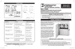
1. Read and follow all instructions.
2. This Control must be installed by a qualified electrician, according to National and Local Electrical Codes.
3. Install this Control not less than 5 feet of inside edge of pool. USE COPPER CONDUCTORS ONLY.
4. Do not exceed the maximum ratings of individual components, wiring devices, and current carrying capacity of
conductors.
5. For grounding and bonding this Control and the installation, refer to section 680 of the National Electrical Code.
6. The Control should not operate any equipment which would cause bodily injury or property damage should it be
activated unexpectedly.
TO SET FILTER TIME SWITCH, follow instructions on the right. The
length of the daily filtration/heating cycle depends on many variables
such as size, shape, and geographic location of the pool, water
chemistry, type of pool equipment, usage and season of year. If not sure,
contact your local pool service professional for advice.
INSTALLATION
1. Select the proper location for the Control Panel and
prepare the necessary conduit run(s) required by the
installation layout.
2. Remove the four #10 hex head screws from the back of
the enclosure and attach mounting brackets to
enclosure.
3. Hang enclosure on a flat vertical surface or other
support, using hardware suitable for the purpose.
4. Properly terminate conduits
at both ends and pull-in the
conductors as specified by
the installation layout.
PRESSURE PLATE
TERMINAL SCREW
MAKE SURE INSULATION
CLEARS PRESSURE PLATE
5. Follow wiring diagram on page 4 of this Manual,
connect LINE1 and LINE 2 OF THE 240 Volt supply
conductors from a 20 Amp. circuit breaker, either in the
main panel or in this subpanel to TB1 terminal block
(see insert above for proper connection) and the
grounding conductor to the Equipment Grounding
Terminal.
6. Connect Filter Pump leads to terminals 2 and 4 of Filter
Pump Time Switch and Cleaner Pump leads to
terminals 2 and 4 of Cleaner Pump leads to terminals 2
and 4 of Cleaner Pump Time Switch. Connect the
grounding leads of each pump to the Equipment
Grounding Terminal at the bottom of the enclosure.
•
enclosure and install stand-offs* in place of screws.
Attach wiring device to stand-offs.
Stand-offs are not furnished. Order 21T156A for a set of four (4)
stand-offs and mounting hardware.
10. If external bonding is required, install bonding lug(s) on
bottom of enclosure (156T11047A may be ordered)
and bond installation according to code requirements.
11. TEST INSTALLATION:
a. Turn the thermostat dial to its lowest setting and
place crushed ice (in plastic bag) inside capillary coil
of Thermostat.
b. Turn ON power to Control Panel, wait 20 seconds
then slowly turn thermostat dial counter-clockwise
until Filter Pump starts.
c. Using the manual lever on Cleaner Time Switch,
turn ON-OFF the Cleaner Pump.
d. Turn OFF power to Control Panel, remove ice,
check wiring, tighten terminal screws if necessary,
reinstall time switch insulators and front plate.
e. Turn ON power to Control Panel and set time
Switches and the Thermostat, see OPERATION
instructions on page 3.
TO SET CLEANER TIME SWITCH, follow instructions on the right.
NOTE: This Control is factory wired to prevent equipment damage by
allowing the Cleaner Pump to operate only when the Filter Pump is
already operating. This requires that the Cleaner Time Switch settings
(ON and OFF times) must be within the operating hours of the Filter
Pump. For example: If the Filter Pump is set to operate from 8 am to 2
pm daily, the Cleaner Pump Time Switch should be set to operate no
longer than 8:30 am to 1:30 pm.
TO SET THERMOSTAT, turn dial, pointing to desired temperature,
marked on the plate, between 32˚F and 45˚F. Again, many variables
must be considered before selecting the “turn ON” temperature of the
Filter Pump and your local pool service professional is the best source of
information. The Thermostat is factory set to turn OFF the Filter Pump
when the ambient temperature rises 5˚F above its set point.
THE FIREMAN SWITCH (Heater Protection Mechanism), if installed, is
factory set and shuts OFF the heater 20 minutes before the Time Switch
turns OFF the filter pump. The Fireman Switch requires no setting or
service.
2. Time Switch Dial stops
at ON or OFF tripper.
4. Dead clock motor. (Clock
motor gears do not rotate.)
5. Filter Pump will not start
when temp. is below 32˚F.
Figure 1
TIME SWITCH OPERATING INSTRUCTIONS
1. TO SET “ON” AND “OFF” TIMES: Hold TRIPPERS
against edge of CLOCK-DIAL, pointing to time (AM or
PM) when ON and OFF operations
CLOCK
DIAL
are desired. Tighten tripper screws
TIME
firmly.
POINTER
2. TO SET TIME-OF-DAY: Pull
OFF
TRIPPER
ON
CLOCK-DIAL outward. Turn in either
MANUAL
TRIPPER
LEVER
direction and align the exact time-ofday on the CLOCK-DIAL (the time now, when switch is
being put into operation) to the POINTER.
DO NOT MOVE POINTER
• TO OPERATE SWITCH MANUALLY: Move MANUAL
LEVER below CLOCK-DIAL left or right as
indicated by arrows, This will not affect next
operation.
• FOR MORE THAN ONE DAILY ON-OFF
OPERATION: Place additional tripper pairs on CLOCKDIAL (order 156T1978A).
• IN CASE OF POWER FAILURE, reset CLOCK-DIAL
to proper time-of-day. See step 2 above.
Figure 2
WARNING: Do not disconnect high limit or pressure switches.
TROUBLESHOOTING
SYMPTOM
1. Time Switch will not keep
time - dial is turning.
7. If the Control Panel is installed in location, where it is
exposed to direct sun most of the day, extend 8 inches
of the copper capillary tube of the thermostat into an
open ended (plastic or metal) conduit, about 10 inches
long, installed at bottom of the enclosure. Handle
capillary tube with care!.
3. Load is ON at all times-dial is turning.
8. If required by the heater manufacturer, install fireman
switch kit 156T4042A (not furnished) on Time Switch
Plate and make the fireman switch connections. Use at
least #18 AWG wiring with insulation rated 300 Volt or
higher. Place heater ON/OFF switch on heater to ON
(see Figure 2). Some heaters may require a special
connecting harness, contact heater manufacturer for
details.
9. To install additional wiring devices inside the
enclosure, first remove rectangular knock-out(s) in
dead front. Next, remove hex head screws in back of
2
CAUSE(S)
CORRECTIVE ACTION
1a. Frequent power outages
1b. Wrong voltage/cycle
1c. Loose clock motor connections
Reset dial
Change clock motor
Check connections
2a. Loose tripper
2b. Bent dial
2c. Defective motor
Check/change tripper
Check/change mechanism
Change clock motor
3a. Welded contacts
3b. Two ON-trippers on dial
3c. No OFF tripper on dial
3d. Defective mechanism
Change
Change
Change
Change
4a. Defective clock motor (open
coil due to lightning or surge)
4b. Loose clock motor connections
4c. Wrong voltage
mechanism
tripper
tripper
mechanism
Change clock motor
Check connections
Change clock motor
5a. Defective thermostat
5b. Defective relay
5c. Faulty wiring
5d. Power outage
Replace thermostat
Replace relay
Check wiring
Install stand-by power
3
BACK
ALL PRINTING TO BE AS PER INTERMATIC
APPROVED ARTWORK.
158PF12441
FRONT
4
INTERMATIC INCORPORATED,
SPRING GROVE, IL. 60081-9698
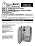
This Pool Equipment Control is designed to automatically operate the Filter Pump, Cleaner Pump
and also to provide freeze protection for the pool equipment. Nevertheless this product is not
intended to be a substitute for insulation, coverings, or maintenance.
Equipment Ground
NOTES:
To 240 V
Breaker
11”
RELEASED TO ELEC. DATA
1
FOLD LINE
SEE B/M FOR ALL PART NUMBERS & QUANTITIES
QUAN.
PT. NO.
DESC.
INTERMATIC INCORPORATED
ITEM
DMB 8/22/2005
APPROVED
DR.: SRB 8/19/2005
CHKD.:
TF 8/22/2005
SCALE:
FINISH:
NAME:
MATL.:
INST SHT - INSTALL, PF1202T
WHITE PAPER STOCK
BLACK PRINTING INK
FRACTIONS + .010 . DECIMALS AS SPECIFIED - ANGLES + 1/2˚
ALL DIMENSIONS MUST BE MET BEFORE PLATING.
:
HEAT TREAT:
DIM
TOL
SUPERSEDES:
MODEL
SIGN.
REVISION
LET.
158PF12441
Because of our commitment to continuing research and improvements, Intermatic Incorporated reserves the right to make
changes, without notice, in the specifications and material contained herein and shall not be responsible for any damages,
direct or consequential, caused by reliance on the material presented.
THE FREEZE PROTECTION THERMOSTAT is
located in the lower left side of the enclosure
and turns ON the Filter Pump when the air
temperature (where the Control Panel is located)
drops below the temperature set by the dial
(between 32˚F and 45˚F).
This warranty service is available, if the defective product or
its defective component is returned with proof of purchase and
date of installation, either (a) to the dealer from whom the unit
was purchased or (b) by shipping prepaid to Intermatic,
Incorporated, Intermatic Plaza, Spring Grove, Il. 60081-9698.
THE CLEANER PUMP TIME SWITCH is located in the upper right side of the enclosure and
operates the Cleaner Pump (Booster Pump). The trippers of this
Time Switch should be set so that the operation of the
Cleaner Pump falls within the operation of the
Filter Pump. To avoid equipment damage, the two
Time Switches are interlocked and the Cleaner
Pump would not operate unless the Filter Pump
is already operating.
The warranty does not cover labor for removal or reinstallation
and does not apply to: (a) damage caused by accident, abuse,
mishandling, or dropping; (b) a unit which has been subject to
unauthorized repair; (c) units not used in accordance with
directions; (d) damages exceeding the cost of the product./
Some states do not allow a limitation of damages so the
foregoing warranty may not apply to you. This warranty gives
you specific legal rights and you may also have other rights
which vary from state to state.
THE FILTER PUMP TIME SWITCH is located in the upper left side of the enclosure and operates
the Filter Pump, as set by the trippers on the yellow dial, on a 24 hour schedule. For setting the
schedule, refer to page 3 of this Manual.
WARRANTY
If within one (1) year from the date of installation, this product
fails due to a defect in material or workmanship, Intermatic
Incorporated will repair or replace it free of charge.
ALTERNATE WIRING FOR
TWO INDEPENDENTLY
WIRED PUMPS
T. Stat
To Filter
Pump
Relay
GENERAL INFORMATION
READ, FOLLOW & SAVE THIS INSTRUCTION MANUAL
To Cleaner
Pump
TB1
Team
Block
...do not permit children to operate the Control Unit or use the Pool/Spa unless they are closely supervised at all times.
...test GROUND FAULT protection regularly. If it fails to reset, DO NOT USE THE POOL or SPA! Contact a qualified
service technician.
...always disconnect electricity before servicing this control or the equipment(s) connected to it. THIS CONTROL IS NOT
TO BE USED AS A POWER DISCONNECT.
DANGER! To Reduce the Risk of Injury:
ELECTRICAL RATING: 3 HP MAX. - 240 VOLT, 60 HZ.
SUITABLE FOR POOL/SPA EQUIPMENT CONTROL
WITH FREEZE PROTECTION IN RAINPROOF ENCLOSURE
TWO CIRCUIT POOL EQUIPMENT CONTROL
MODEL: PF1202T
NOTE: Ground connections
are not shown and
vary with installation.
WIRING
DIAGRAM
INSTALLATION
OPERATION &
SERVICE MANUAL
FREEZE PROTECTION FOR POOLS AND SPAS
240 V.
CLOCK
MOTOR
Cleaner Control
Time Switch
By
FREEZE PROTECTION
By
FOR POOLS, SPAS
AND WATER FEATURES
240 V.
CLOCK
MOTOR
®
81/2”
Filter Control
Time Switch
6. Connect Filter Pump leads to terminals 2 and 4 of Filter
Pump Time Switch and Cleaner Pump leads to
terminals 2 and 4 of Cleaner Pump leads to terminals 2
and 4 of Cleaner Pump Time Switch. Connect the
grounding leads of each pump to the Equipment
Grounding Terminal at the bottom of the enclosure.
2. Time Switch Dial stops
at ON or OFF tripper.
4. Dead clock motor. (Clock
motor gears do not rotate.)
Figure 1
2
Reset dial
Change clock motor
Check connections
3a. Welded contacts
3b. Two ON-trippers on dial
3c. No OFF tripper on dial
3d. Defective mechanism
Change
Change
Change
Change
FINISH:
DMB 8/22/2005
mechanism
tripper
tripper
mechanism
Change clock motor
Check connections
Change clock motor
5a. Defective thermostat
5b. Defective relay
5c. Faulty wiring
5d. Power outage
Replace thermostat
Replace relay
Check wiring
Install stand-by power
3
BACK
:
HEAT TREAT:
DIM
TOL
INST SHT - INSTALL, PF1202T
WHITE PAPER STOCK
BLACK PRINTING INK
NAME:
MATL.:
APPROVED
Check/change tripper
Check/change mechanism
Change clock motor
4a. Defective clock motor (open
coil due to lightning or surge)
4b. Loose clock motor connections
4c. Wrong voltage
5. Filter Pump will not start
when temp. is below 32˚F.
SUPERSEDES:
INTERMATIC INCORPORATED
DR.: SRB 8/19/2005
CHKD.:
TF 8/22/2005
SCALE:
MODEL
1a. Frequent power outages
1b. Wrong voltage/cycle
1c. Loose clock motor connections
FRONT
4
INTERMATIC INCORPORATED,
SPRING GROVE, IL. 60081-9698
Because of our commitment to continuing research and improvements, Intermatic Incorporated reserves the right to make
changes, without notice, in the specifications and material contained herein and shall not be responsible for any damages,
direct or consequential, caused by reliance on the material presented.
This warranty service is available, if the defective product or
its defective component is returned with proof of purchase and
date of installation, either (a) to the dealer from whom the unit
was purchased or (b) by shipping prepaid to Intermatic,
Incorporated, Intermatic Plaza, Spring Grove, Il. 60081-9698.
The warranty does not cover labor for removal or reinstallation
and does not apply to: (a) damage caused by accident, abuse,
mishandling, or dropping; (b) a unit which has been subject to
unauthorized repair; (c) units not used in accordance with
directions; (d) damages exceeding the cost of the product./
Some states do not allow a limitation of damages so the
foregoing warranty may not apply to you. This warranty gives
you specific legal rights and you may also have other rights
which vary from state to state.
WARRANTY
If within one (1) year from the date of installation, this product
fails due to a defect in material or workmanship, Intermatic
Incorporated will repair or replace it free of charge.
T. Stat
NOTES:
To Filter
Pump
Equipment Ground
To 240 V
Breaker
TB1
Team
Block
THE FREEZE PROTECTION THERMOSTAT is
located in the lower left side of the enclosure
and turns ON the Filter Pump when the air
temperature (where the Control Panel is located)
drops below the temperature set by the dial
(between 32˚F and 45˚F).
THE CLEANER PUMP TIME SWITCH is located in the upper right side of the enclosure and
operates the Cleaner Pump (Booster Pump). The trippers of this
Time Switch should be set so that the operation of the
Cleaner Pump falls within the operation of the
Filter Pump. To avoid equipment damage, the two
Time Switches are interlocked and the Cleaner
Pump would not operate unless the Filter Pump
is already operating.
THE FILTER PUMP TIME SWITCH is located in the upper left side of the enclosure and operates
the Filter Pump, as set by the trippers on the yellow dial, on a 24 hour schedule. For setting the
schedule, refer to page 3 of this Manual.
This Pool Equipment Control is designed to automatically operate the Filter Pump, Cleaner Pump
and also to provide freeze protection for the pool equipment. Nevertheless this product is not
intended to be a substitute for insulation, coverings, or maintenance.
GENERAL INFORMATION
To Cleaner
Pump
READ, FOLLOW & SAVE THIS INSTRUCTION MANUAL
...do not permit children to operate the Control Unit or use the Pool/Spa unless they are closely supervised at all times.
...test GROUND FAULT protection regularly. If it fails to reset, DO NOT USE THE POOL or SPA! Contact a qualified
service technician.
...always disconnect electricity before servicing this control or the equipment(s) connected to it. THIS CONTROL IS NOT
TO BE USED AS A POWER DISCONNECT.
DANGER! To Reduce the Risk of Injury:
ELECTRICAL RATING: 3 HP MAX. - 240 VOLT, 60 HZ.
SUITABLE FOR POOL/SPA EQUIPMENT CONTROL
WITH FREEZE PROTECTION IN RAINPROOF ENCLOSURE
TWO CIRCUIT POOL EQUIPMENT CONTROL
MODEL: PF1202T
NOTE: Ground connections
are not shown and
vary with installation.
WIRING
DIAGRAM
FREEZE PROTECTION FOR POOLS AND SPAS
Filter Control
Time Switch
240 V.
CLOCK
MOTOR
Cleaner Control
Time Switch
240 V.
CLOCK
MOTOR
FREEZE PROTECTION
By
FOR POOLS, SPAS
AND WATER FEATURES
By
®
81/2”
ITEM
CORRECTIVE ACTION
2a. Loose tripper
2b. Bent dial
2c. Defective motor
3. Load is ON at all times-dial is turning.
9. To install additional wiring devices inside the
enclosure, first remove rectangular knock-out(s) in
dead front. Next, remove hex head screws in back of
WARNING: Do not disconnect high limit or pressure switches.
CAUSE(S)
1. Time Switch will not keep
time - dial is turning.
8. If required by the heater manufacturer, install fireman
switch kit 156T4042A (not furnished) on Time Switch
Plate and make the fireman switch connections. Use at
least #18 AWG wiring with insulation rated 300 Volt or
higher. Place heater ON/OFF switch on heater to ON
(see Figure 2). Some heaters may require a special
connecting harness, contact heater manufacturer for
details.
Figure 2
TROUBLESHOOTING
SYMPTOM
7. If the Control Panel is installed in location, where it is
exposed to direct sun most of the day, extend 8 inches
of the copper capillary tube of the thermostat into an
open ended (plastic or metal) conduit, about 10 inches
long, installed at bottom of the enclosure. Handle
capillary tube with care!.
SIGN.
THE FIREMAN SWITCH (Heater Protection Mechanism), if installed, is
factory set and shuts OFF the heater 20 minutes before the Time Switch
turns OFF the filter pump. The Fireman Switch requires no setting or
service.
REVISION
5. Follow wiring diagram on page 4 of this Manual,
connect LINE1 and LINE 2 OF THE 240 Volt supply
conductors from a 20 Amp. circuit breaker, either in the
main panel or in this subpanel to TB1 terminal block
(see insert above for proper connection) and the
grounding conductor to the Equipment Grounding
Terminal.
LET.
MAKE SURE INSULATION
CLEARS PRESSURE PLATE
RELEASED TO ELEC. DATA
TERMINAL SCREW
1
4. Properly terminate conduits
at both ends and pull-in the
conductors as specified by
the installation layout.
11. TEST INSTALLATION:
a. Turn the thermostat dial to its lowest setting and
place crushed ice (in plastic bag) inside capillary coil
of Thermostat.
b. Turn ON power to Control Panel, wait 20 seconds
then slowly turn thermostat dial counter-clockwise
until Filter Pump starts.
c. Using the manual lever on Cleaner Time Switch,
turn ON-OFF the Cleaner Pump.
d. Turn OFF power to Control Panel, remove ice,
check wiring, tighten terminal screws if necessary,
reinstall time switch insulators and front plate.
e. Turn ON power to Control Panel and set time
Switches and the Thermostat, see OPERATION
instructions on page 3.
PRESSURE PLATE
ALL PRINTING TO BE AS PER INTERMATIC
APPROVED ARTWORK.
3. Hang enclosure on a flat vertical surface or other
support, using hardware suitable for the purpose.
TO SET THERMOSTAT, turn dial, pointing to desired temperature,
marked on the plate, between 32˚F and 45˚F. Again, many variables
must be considered before selecting the “turn ON” temperature of the
Filter Pump and your local pool service professional is the best source of
information. The Thermostat is factory set to turn OFF the Filter Pump
when the ambient temperature rises 5˚F above its set point.
FRACTIONS + .010 . DECIMALS AS SPECIFIED - ANGLES + 1/2˚
ALL DIMENSIONS MUST BE MET BEFORE PLATING.
QUAN.
DESC.
10. If external bonding is required, install bonding lug(s) on
bottom of enclosure (156T11047A may be ordered)
and bond installation according to code requirements.
PT. NO.
FOLD LINE
2. Remove the four #10 hex head screws from the back of
the enclosure and attach mounting brackets to
enclosure.
Stand-offs are not furnished. Order 21T156A for a set of four (4)
stand-offs and mounting hardware.
TO SET CLEANER TIME SWITCH, follow instructions on the right.
NOTE: This Control is factory wired to prevent equipment damage by
allowing the Cleaner Pump to operate only when the Filter Pump is
already operating. This requires that the Cleaner Time Switch settings
(ON and OFF times) must be within the operating hours of the Filter
Pump. For example: If the Filter Pump is set to operate from 8 am to 2
pm daily, the Cleaner Pump Time Switch should be set to operate no
longer than 8:30 am to 1:30 pm.
TIME SWITCH OPERATING INSTRUCTIONS
1. TO SET “ON” AND “OFF” TIMES: Hold TRIPPERS
against edge of CLOCK-DIAL, pointing to time (AM or
PM) when ON and OFF operations
CLOCK
DIAL
are desired. Tighten tripper screws
TIME
firmly.
POINTER
2. TO SET TIME-OF-DAY: Pull
OFF
TRIPPER
ON
CLOCK-DIAL outward. Turn in either
MANUAL
TRIPPER
LEVER
direction and align the exact time-ofday on the CLOCK-DIAL (the time now, when switch is
being put into operation) to the POINTER.
DO NOT MOVE POINTER
• TO OPERATE SWITCH MANUALLY: Move MANUAL
LEVER below CLOCK-DIAL left or right as
indicated by arrows, This will not affect next
operation.
• FOR MORE THAN ONE DAILY ON-OFF
OPERATION: Place additional tripper pairs on CLOCKDIAL (order 156T1978A).
• IN CASE OF POWER FAILURE, reset CLOCK-DIAL
to proper time-of-day. See step 2 above.
Relay
•
enclosure and install stand-offs* in place of screws.
Attach wiring device to stand-offs.
TO SET FILTER TIME SWITCH, follow instructions on the right. The
length of the daily filtration/heating cycle depends on many variables
such as size, shape, and geographic location of the pool, water
chemistry, type of pool equipment, usage and season of year. If not sure,
contact your local pool service professional for advice.
ALTERNATE WIRING FOR
TWO INDEPENDENTLY
WIRED PUMPS
1. Select the proper location for the Control Panel and
prepare the necessary conduit run(s) required by the
installation layout.
OPERATION
158PF12441
INSTALLATION
INSTALLATION
OPERATION &
SERVICE MANUAL
11”
SEE B/M FOR ALL PART NUMBERS & QUANTITIES
158PF12441
IMPORTANT SAFETY INSTRUCTIONS
When installing and operating this electrical control and other associated equipment, basic safety precautions should
always be followed, including the following:
1. Read and follow all instructions.
2. This Control must be installed by a qualified electrician, according to National and Local Electrical Codes.
3. Install this Control not less than 5 feet of inside edge of pool. USE COPPER CONDUCTORS ONLY.
4. Do not exceed the maximum ratings of individual components, wiring devices, and current carrying capacity of
conductors.
5. For grounding and bonding this Control and the installation, refer to section 680 of the National Electrical Code.
6. The Control should not operate any equipment which would cause bodily injury or property damage should it be
activated unexpectedly.
6. Connect Filter Pump leads to terminals 2 and 4 of Filter
Pump Time Switch and Cleaner Pump leads to
terminals 2 and 4 of Cleaner Pump leads to terminals 2
and 4 of Cleaner Pump Time Switch. Connect the
grounding leads of each pump to the Equipment
Grounding Terminal at the bottom of the enclosure.
2. Time Switch Dial stops
at ON or OFF tripper.
4. Dead clock motor. (Clock
motor gears do not rotate.)
Figure 1
2
Reset dial
Change clock motor
Check connections
3a. Welded contacts
3b. Two ON-trippers on dial
3c. No OFF tripper on dial
3d. Defective mechanism
Change
Change
Change
Change
FINISH:
DMB 8/22/2005
mechanism
tripper
tripper
mechanism
Change clock motor
Check connections
Change clock motor
5a. Defective thermostat
5b. Defective relay
5c. Faulty wiring
5d. Power outage
Replace thermostat
Replace relay
Check wiring
Install stand-by power
3
BACK
:
HEAT TREAT:
DIM
TOL
INST SHT - INSTALL, PF1202T
WHITE PAPER STOCK
BLACK PRINTING INK
NAME:
MATL.:
APPROVED
Check/change tripper
Check/change mechanism
Change clock motor
4a. Defective clock motor (open
coil due to lightning or surge)
4b. Loose clock motor connections
4c. Wrong voltage
5. Filter Pump will not start
when temp. is below 32˚F.
SUPERSEDES:
INTERMATIC INCORPORATED
DR.: SRB 8/19/2005
CHKD.:
TF 8/22/2005
SCALE:
MODEL
1a. Frequent power outages
1b. Wrong voltage/cycle
1c. Loose clock motor connections
FRONT
4
INTERMATIC INCORPORATED,
SPRING GROVE, IL. 60081-9698
Because of our commitment to continuing research and improvements, Intermatic Incorporated reserves the right to make
changes, without notice, in the specifications and material contained herein and shall not be responsible for any damages,
direct or consequential, caused by reliance on the material presented.
This warranty service is available, if the defective product or
its defective component is returned with proof of purchase and
date of installation, either (a) to the dealer from whom the unit
was purchased or (b) by shipping prepaid to Intermatic,
Incorporated, Intermatic Plaza, Spring Grove, Il. 60081-9698.
The warranty does not cover labor for removal or reinstallation
and does not apply to: (a) damage caused by accident, abuse,
mishandling, or dropping; (b) a unit which has been subject to
unauthorized repair; (c) units not used in accordance with
directions; (d) damages exceeding the cost of the product./
Some states do not allow a limitation of damages so the
foregoing warranty may not apply to you. This warranty gives
you specific legal rights and you may also have other rights
which vary from state to state.
WARRANTY
If within one (1) year from the date of installation, this product
fails due to a defect in material or workmanship, Intermatic
Incorporated will repair or replace it free of charge.
T. Stat
NOTES:
To Filter
Pump
Equipment Ground
To 240 V
Breaker
TB1
Team
Block
THE FREEZE PROTECTION THERMOSTAT is
located in the lower left side of the enclosure
and turns ON the Filter Pump when the air
temperature (where the Control Panel is located)
drops below the temperature set by the dial
(between 32˚F and 45˚F).
THE CLEANER PUMP TIME SWITCH is located in the upper right side of the enclosure and
operates the Cleaner Pump (Booster Pump). The trippers of this
Time Switch should be set so that the operation of the
Cleaner Pump falls within the operation of the
Filter Pump. To avoid equipment damage, the two
Time Switches are interlocked and the Cleaner
Pump would not operate unless the Filter Pump
is already operating.
THE FILTER PUMP TIME SWITCH is located in the upper left side of the enclosure and operates
the Filter Pump, as set by the trippers on the yellow dial, on a 24 hour schedule. For setting the
schedule, refer to page 3 of this Manual.
This Pool Equipment Control is designed to automatically operate the Filter Pump, Cleaner Pump
and also to provide freeze protection for the pool equipment. Nevertheless this product is not
intended to be a substitute for insulation, coverings, or maintenance.
GENERAL INFORMATION
To Cleaner
Pump
READ, FOLLOW & SAVE THIS INSTRUCTION MANUAL
...do not permit children to operate the Control Unit or use the Pool/Spa unless they are closely supervised at all times.
...test GROUND FAULT protection regularly. If it fails to reset, DO NOT USE THE POOL or SPA! Contact a qualified
service technician.
...always disconnect electricity before servicing this control or the equipment(s) connected to it. THIS CONTROL IS NOT
TO BE USED AS A POWER DISCONNECT.
DANGER! To Reduce the Risk of Injury:
ELECTRICAL RATING: 3 HP MAX. - 240 VOLT, 60 HZ.
SUITABLE FOR POOL/SPA EQUIPMENT CONTROL
WITH FREEZE PROTECTION IN RAINPROOF ENCLOSURE
TWO CIRCUIT POOL EQUIPMENT CONTROL
MODEL: PF1202T
NOTE: Ground connections
are not shown and
vary with installation.
WIRING
DIAGRAM
FREEZE PROTECTION FOR POOLS AND SPAS
Filter Control
Time Switch
240 V.
CLOCK
MOTOR
Cleaner Control
Time Switch
240 V.
CLOCK
MOTOR
FREEZE PROTECTION
By
FOR POOLS, SPAS
AND WATER FEATURES
By
®
81/2”
ITEM
CORRECTIVE ACTION
2a. Loose tripper
2b. Bent dial
2c. Defective motor
3. Load is ON at all times-dial is turning.
9. To install additional wiring devices inside the
enclosure, first remove rectangular knock-out(s) in
dead front. Next, remove hex head screws in back of
WARNING: Do not disconnect high limit or pressure switches.
CAUSE(S)
1. Time Switch will not keep
time - dial is turning.
8. If required by the heater manufacturer, install fireman
switch kit 156T4042A (not furnished) on Time Switch
Plate and make the fireman switch connections. Use at
least #18 AWG wiring with insulation rated 300 Volt or
higher. Place heater ON/OFF switch on heater to ON
(see Figure 2). Some heaters may require a special
connecting harness, contact heater manufacturer for
details.
Figure 2
TROUBLESHOOTING
SYMPTOM
7. If the Control Panel is installed in location, where it is
exposed to direct sun most of the day, extend 8 inches
of the copper capillary tube of the thermostat into an
open ended (plastic or metal) conduit, about 10 inches
long, installed at bottom of the enclosure. Handle
capillary tube with care!.
SIGN.
THE FIREMAN SWITCH (Heater Protection Mechanism), if installed, is
factory set and shuts OFF the heater 20 minutes before the Time Switch
turns OFF the filter pump. The Fireman Switch requires no setting or
service.
REVISION
5. Follow wiring diagram on page 4 of this Manual,
connect LINE1 and LINE 2 OF THE 240 Volt supply
conductors from a 20 Amp. circuit breaker, either in the
main panel or in this subpanel to TB1 terminal block
(see insert above for proper connection) and the
grounding conductor to the Equipment Grounding
Terminal.
LET.
MAKE SURE INSULATION
CLEARS PRESSURE PLATE
RELEASED TO ELEC. DATA
TERMINAL SCREW
1
4. Properly terminate conduits
at both ends and pull-in the
conductors as specified by
the installation layout.
11. TEST INSTALLATION:
a. Turn the thermostat dial to its lowest setting and
place crushed ice (in plastic bag) inside capillary coil
of Thermostat.
b. Turn ON power to Control Panel, wait 20 seconds
then slowly turn thermostat dial counter-clockwise
until Filter Pump starts.
c. Using the manual lever on Cleaner Time Switch,
turn ON-OFF the Cleaner Pump.
d. Turn OFF power to Control Panel, remove ice,
check wiring, tighten terminal screws if necessary,
reinstall time switch insulators and front plate.
e. Turn ON power to Control Panel and set time
Switches and the Thermostat, see OPERATION
instructions on page 3.
PRESSURE PLATE
ALL PRINTING TO BE AS PER INTERMATIC
APPROVED ARTWORK.
3. Hang enclosure on a flat vertical surface or other
support, using hardware suitable for the purpose.
TO SET THERMOSTAT, turn dial, pointing to desired temperature,
marked on the plate, between 32˚F and 45˚F. Again, many variables
must be considered before selecting the “turn ON” temperature of the
Filter Pump and your local pool service professional is the best source of
information. The Thermostat is factory set to turn OFF the Filter Pump
when the ambient temperature rises 5˚F above its set point.
FRACTIONS + .010 . DECIMALS AS SPECIFIED - ANGLES + 1/2˚
ALL DIMENSIONS MUST BE MET BEFORE PLATING.
QUAN.
DESC.
10. If external bonding is required, install bonding lug(s) on
bottom of enclosure (156T11047A may be ordered)
and bond installation according to code requirements.
PT. NO.
FOLD LINE
2. Remove the four #10 hex head screws from the back of
the enclosure and attach mounting brackets to
enclosure.
Stand-offs are not furnished. Order 21T156A for a set of four (4)
stand-offs and mounting hardware.
TO SET CLEANER TIME SWITCH, follow instructions on the right.
NOTE: This Control is factory wired to prevent equipment damage by
allowing the Cleaner Pump to operate only when the Filter Pump is
already operating. This requires that the Cleaner Time Switch settings
(ON and OFF times) must be within the operating hours of the Filter
Pump. For example: If the Filter Pump is set to operate from 8 am to 2
pm daily, the Cleaner Pump Time Switch should be set to operate no
longer than 8:30 am to 1:30 pm.
TIME SWITCH OPERATING INSTRUCTIONS
1. TO SET “ON” AND “OFF” TIMES: Hold TRIPPERS
against edge of CLOCK-DIAL, pointing to time (AM or
PM) when ON and OFF operations
CLOCK
DIAL
are desired. Tighten tripper screws
TIME
firmly.
POINTER
2. TO SET TIME-OF-DAY: Pull
OFF
TRIPPER
ON
CLOCK-DIAL outward. Turn in either
MANUAL
TRIPPER
LEVER
direction and align the exact time-ofday on the CLOCK-DIAL (the time now, when switch is
being put into operation) to the POINTER.
DO NOT MOVE POINTER
• TO OPERATE SWITCH MANUALLY: Move MANUAL
LEVER below CLOCK-DIAL left or right as
indicated by arrows, This will not affect next
operation.
• FOR MORE THAN ONE DAILY ON-OFF
OPERATION: Place additional tripper pairs on CLOCKDIAL (order 156T1978A).
• IN CASE OF POWER FAILURE, reset CLOCK-DIAL
to proper time-of-day. See step 2 above.
Relay
•
enclosure and install stand-offs* in place of screws.
Attach wiring device to stand-offs.
TO SET FILTER TIME SWITCH, follow instructions on the right. The
length of the daily filtration/heating cycle depends on many variables
such as size, shape, and geographic location of the pool, water
chemistry, type of pool equipment, usage and season of year. If not sure,
contact your local pool service professional for advice.
ALTERNATE WIRING FOR
TWO INDEPENDENTLY
WIRED PUMPS
1. Select the proper location for the Control Panel and
prepare the necessary conduit run(s) required by the
installation layout.
OPERATION
158PF12441
INSTALLATION
INSTALLATION
OPERATION &
SERVICE MANUAL
11”
SEE B/M FOR ALL PART NUMBERS & QUANTITIES
158PF12441
IMPORTANT SAFETY INSTRUCTIONS
When installing and operating this electrical control and other associated equipment, basic safety precautions should
always be followed, including the following:
1. Read and follow all instructions.
2. This Control must be installed by a qualified electrician, according to National and Local Electrical Codes.
3. Install this Control not less than 5 feet of inside edge of pool. USE COPPER CONDUCTORS ONLY.
4. Do not exceed the maximum ratings of individual components, wiring devices, and current carrying capacity of
conductors.
5. For grounding and bonding this Control and the installation, refer to section 680 of the National Electrical Code.
6. The Control should not operate any equipment which would cause bodily injury or property damage should it be
activated unexpectedly.
IMPORTANT SAFETY INSTRUCTIONS
OPERATION
When installing and operating this electrical control and other associated equipment, basic safety precautions should
always be followed, including the following:
1. Read and follow all instructions.
2. This Control must be installed by a qualified electrician, according to National and Local Electrical Codes.
3. Install this Control not less than 5 feet of inside edge of pool. USE COPPER CONDUCTORS ONLY.
4. Do not exceed the maximum ratings of individual components, wiring devices, and current carrying capacity of
conductors.
5. For grounding and bonding this Control and the installation, refer to section 680 of the National Electrical Code.
6. The Control should not operate any equipment which would cause bodily injury or property damage should it be
activated unexpectedly.
TO SET FILTER TIME SWITCH, follow instructions on the right. The
length of the daily filtration/heating cycle depends on many variables
such as size, shape, and geographic location of the pool, water
chemistry, type of pool equipment, usage and season of year. If not sure,
contact your local pool service professional for advice.
INSTALLATION
1. Select the proper location for the Control Panel and
prepare the necessary conduit run(s) required by the
installation layout.
2. Remove the four #10 hex head screws from the back of
the enclosure and attach mounting brackets to
enclosure.
3. Hang enclosure on a flat vertical surface or other
support, using hardware suitable for the purpose.
4. Properly terminate conduits
at both ends and pull-in the
conductors as specified by
the installation layout.
PRESSURE PLATE
TERMINAL SCREW
MAKE SURE INSULATION
CLEARS PRESSURE PLATE
5. Follow wiring diagram on page 4 of this Manual,
connect LINE1 and LINE 2 OF THE 240 Volt supply
conductors from a 20 Amp. circuit breaker, either in the
main panel or in this subpanel to TB1 terminal block
(see insert above for proper connection) and the
grounding conductor to the Equipment Grounding
Terminal.
6. Connect Filter Pump leads to terminals 2 and 4 of Filter
Pump Time Switch and Cleaner Pump leads to
terminals 2 and 4 of Cleaner Pump leads to terminals 2
and 4 of Cleaner Pump Time Switch. Connect the
grounding leads of each pump to the Equipment
Grounding Terminal at the bottom of the enclosure.
•
enclosure and install stand-offs* in place of screws.
Attach wiring device to stand-offs.
Stand-offs are not furnished. Order 21T156A for a set of four (4)
stand-offs and mounting hardware.
10. If external bonding is required, install bonding lug(s) on
bottom of enclosure (156T11047A may be ordered)
and bond installation according to code requirements.
11. TEST INSTALLATION:
a. Turn the thermostat dial to its lowest setting and
place crushed ice (in plastic bag) inside capillary coil
of Thermostat.
b. Turn ON power to Control Panel, wait 20 seconds
then slowly turn thermostat dial counter-clockwise
until Filter Pump starts.
c. Using the manual lever on Cleaner Time Switch,
turn ON-OFF the Cleaner Pump.
d. Turn OFF power to Control Panel, remove ice,
check wiring, tighten terminal screws if necessary,
reinstall time switch insulators and front plate.
e. Turn ON power to Control Panel and set time
Switches and the Thermostat, see OPERATION
instructions on page 3.
TO SET CLEANER TIME SWITCH, follow instructions on the right.
NOTE: This Control is factory wired to prevent equipment damage by
allowing the Cleaner Pump to operate only when the Filter Pump is
already operating. This requires that the Cleaner Time Switch settings
(ON and OFF times) must be within the operating hours of the Filter
Pump. For example: If the Filter Pump is set to operate from 8 am to 2
pm daily, the Cleaner Pump Time Switch should be set to operate no
longer than 8:30 am to 1:30 pm.
TO SET THERMOSTAT, turn dial, pointing to desired temperature,
marked on the plate, between 32˚F and 45˚F. Again, many variables
must be considered before selecting the “turn ON” temperature of the
Filter Pump and your local pool service professional is the best source of
information. The Thermostat is factory set to turn OFF the Filter Pump
when the ambient temperature rises 5˚F above its set point.
THE FIREMAN SWITCH (Heater Protection Mechanism), if installed, is
factory set and shuts OFF the heater 20 minutes before the Time Switch
turns OFF the filter pump. The Fireman Switch requires no setting or
service.
2. Time Switch Dial stops
at ON or OFF tripper.
4. Dead clock motor. (Clock
motor gears do not rotate.)
5. Filter Pump will not start
when temp. is below 32˚F.
Figure 1
TIME SWITCH OPERATING INSTRUCTIONS
1. TO SET “ON” AND “OFF” TIMES: Hold TRIPPERS
against edge of CLOCK-DIAL, pointing to time (AM or
PM) when ON and OFF operations
CLOCK
DIAL
are desired. Tighten tripper screws
TIME
firmly.
POINTER
2. TO SET TIME-OF-DAY: Pull
OFF
TRIPPER
ON
CLOCK-DIAL outward. Turn in either
MANUAL
TRIPPER
LEVER
direction and align the exact time-ofday on the CLOCK-DIAL (the time now, when switch is
being put into operation) to the POINTER.
DO NOT MOVE POINTER
• TO OPERATE SWITCH MANUALLY: Move MANUAL
LEVER below CLOCK-DIAL left or right as
indicated by arrows, This will not affect next
operation.
• FOR MORE THAN ONE DAILY ON-OFF
OPERATION: Place additional tripper pairs on CLOCKDIAL (order 156T1978A).
• IN CASE OF POWER FAILURE, reset CLOCK-DIAL
to proper time-of-day. See step 2 above.
Figure 2
WARNING: Do not disconnect high limit or pressure switches.
TROUBLESHOOTING
SYMPTOM
1. Time Switch will not keep
time - dial is turning.
7. If the Control Panel is installed in location, where it is
exposed to direct sun most of the day, extend 8 inches
of the copper capillary tube of the thermostat into an
open ended (plastic or metal) conduit, about 10 inches
long, installed at bottom of the enclosure. Handle
capillary tube with care!.
3. Load is ON at all times-dial is turning.
8. If required by the heater manufacturer, install fireman
switch kit 156T4042A (not furnished) on Time Switch
Plate and make the fireman switch connections. Use at
least #18 AWG wiring with insulation rated 300 Volt or
higher. Place heater ON/OFF switch on heater to ON
(see Figure 2). Some heaters may require a special
connecting harness, contact heater manufacturer for
details.
9. To install additional wiring devices inside the
enclosure, first remove rectangular knock-out(s) in
dead front. Next, remove hex head screws in back of
2
CAUSE(S)
CORRECTIVE ACTION
1a. Frequent power outages
1b. Wrong voltage/cycle
1c. Loose clock motor connections
Reset dial
Change clock motor
Check connections
2a. Loose tripper
2b. Bent dial
2c. Defective motor
Check/change tripper
Check/change mechanism
Change clock motor
3a. Welded contacts
3b. Two ON-trippers on dial
3c. No OFF tripper on dial
3d. Defective mechanism
Change
Change
Change
Change
4a. Defective clock motor (open
coil due to lightning or surge)
4b. Loose clock motor connections
4c. Wrong voltage
mechanism
tripper
tripper
mechanism
Change clock motor
Check connections
Change clock motor
5a. Defective thermostat
5b. Defective relay
5c. Faulty wiring
5d. Power outage
Replace thermostat
Replace relay
Check wiring
Install stand-by power
3
BACK
ALL PRINTING TO BE AS PER INTERMATIC
APPROVED ARTWORK.
158PF12441
FRONT
4
INTERMATIC INCORPORATED,
SPRING GROVE, IL. 60081-9698
This Pool Equipment Control is designed to automatically operate the Filter Pump, Cleaner Pump
and also to provide freeze protection for the pool equipment. Nevertheless this product is not
intended to be a substitute for insulation, coverings, or maintenance.
Equipment Ground
NOTES:
To 240 V
Breaker
11”
RELEASED TO ELEC. DATA
1
FOLD LINE
SEE B/M FOR ALL PART NUMBERS & QUANTITIES
QUAN.
PT. NO.
DESC.
INTERMATIC INCORPORATED
ITEM
DMB 8/22/2005
APPROVED
DR.: SRB 8/19/2005
CHKD.:
TF 8/22/2005
SCALE:
FINISH:
NAME:
MATL.:
INST SHT - INSTALL, PF1202T
WHITE PAPER STOCK
BLACK PRINTING INK
FRACTIONS + .010 . DECIMALS AS SPECIFIED - ANGLES + 1/2˚
ALL DIMENSIONS MUST BE MET BEFORE PLATING.
:
HEAT TREAT:
DIM
TOL
SUPERSEDES:
MODEL
SIGN.
REVISION
LET.
158PF12441
Because of our commitment to continuing research and improvements, Intermatic Incorporated reserves the right to make
changes, without notice, in the specifications and material contained herein and shall not be responsible for any damages,
direct or consequential, caused by reliance on the material presented.
THE FREEZE PROTECTION THERMOSTAT is
located in the lower left side of the enclosure
and turns ON the Filter Pump when the air
temperature (where the Control Panel is located)
drops below the temperature set by the dial
(between 32˚F and 45˚F).
This warranty service is available, if the defective product or
its defective component is returned with proof of purchase and
date of installation, either (a) to the dealer from whom the unit
was purchased or (b) by shipping prepaid to Intermatic,
Incorporated, Intermatic Plaza, Spring Grove, Il. 60081-9698.
THE CLEANER PUMP TIME SWITCH is located in the upper right side of the enclosure and
operates the Cleaner Pump (Booster Pump). The trippers of this
Time Switch should be set so that the operation of the
Cleaner Pump falls within the operation of the
Filter Pump. To avoid equipment damage, the two
Time Switches are interlocked and the Cleaner
Pump would not operate unless the Filter Pump
is already operating.
The warranty does not cover labor for removal or reinstallation
and does not apply to: (a) damage caused by accident, abuse,
mishandling, or dropping; (b) a unit which has been subject to
unauthorized repair; (c) units not used in accordance with
directions; (d) damages exceeding the cost of the product./
Some states do not allow a limitation of damages so the
foregoing warranty may not apply to you. This warranty gives
you specific legal rights and you may also have other rights
which vary from state to state.
THE FILTER PUMP TIME SWITCH is located in the upper left side of the enclosure and operates
the Filter Pump, as set by the trippers on the yellow dial, on a 24 hour schedule. For setting the
schedule, refer to page 3 of this Manual.
WARRANTY
If within one (1) year from the date of installation, this product
fails due to a defect in material or workmanship, Intermatic
Incorporated will repair or replace it free of charge.
ALTERNATE WIRING FOR
TWO INDEPENDENTLY
WIRED PUMPS
T. Stat
To Filter
Pump
Relay
GENERAL INFORMATION
READ, FOLLOW & SAVE THIS INSTRUCTION MANUAL
To Cleaner
Pump
TB1
Team
Block
...do not permit children to operate the Control Unit or use the Pool/Spa unless they are closely supervised at all times.
...test GROUND FAULT protection regularly. If it fails to reset, DO NOT USE THE POOL or SPA! Contact a qualified
service technician.
...always disconnect electricity before servicing this control or the equipment(s) connected to it. THIS CONTROL IS NOT
TO BE USED AS A POWER DISCONNECT.
DANGER! To Reduce the Risk of Injury:
ELECTRICAL RATING: 3 HP MAX. - 240 VOLT, 60 HZ.
SUITABLE FOR POOL/SPA EQUIPMENT CONTROL
WITH FREEZE PROTECTION IN RAINPROOF ENCLOSURE
TWO CIRCUIT POOL EQUIPMENT CONTROL
MODEL: PF1202T
NOTE: Ground connections
are not shown and
vary with installation.
WIRING
DIAGRAM
INSTALLATION
OPERATION &
SERVICE MANUAL
FREEZE PROTECTION FOR POOLS AND SPAS
240 V.
CLOCK
MOTOR
Cleaner Control
Time Switch
By
FREEZE PROTECTION
By
FOR POOLS, SPAS
AND WATER FEATURES
240 V.
CLOCK
MOTOR
®
81/2”
Filter Control
Time Switch