1
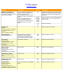
RCI 2950 Service Manual
PARTS LISTS
●
●
●
Table of Contents
●
●
●
●
●
●
●
●
●
●
●
Specifications
Controls and Connections
Basic Programming Procedures
Technical Analysis of the circuits
Transistors Voltage Chart
RCI SECRETS
REPAIR TRICKS
RADIO MODIFICATIONS
●
●
●
●
●
DIAGRAMS
●
●
●
●
●
●
Main PCB Schematic Diagram
CPU PCB Schematic Diagram
Chassis Exploded View Drawing
Inter-connection Diagram
●
●
●
●
●
●
PCB Layouts and Parts
●
●
●
●
●
●
●
●
●
●
●
●
●
●
●
(EPT295013Z)
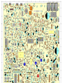
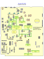
Main PCB Parts Layout Top View
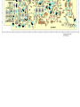
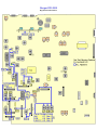
Main PCB Copper Side View
LCD PCB (EPT295021Z)
CPU PCB (EPT295043Z)
MIC UP/DW (EPT295080Z)
MIC Jack PCB (EPT295070Z)
SWR PCB (EPT360040Z)
VR (A) PCB RF/MIC VOL/SQ (EPT295050Z)
VR (B) PCB RF/CAL (EPT295060Z)
CH / Switch PCB (EPT295090A)
MODE PCB (EPT295090Z)
Push Button Switch PCB (EPT295031Z)
Capacitors
Coils, Transformers, Crystals, Filters
Resistors
IC's, Transistors
Diodes
Wire, Jumpers, Connectors
Chassis, Miscellaneous & Mechanical Parts
●
●
●
●
MODIFY FOR 26 Mhz -32 Mhz
MODIFY FOR 25 Mhz -33 Mhz
Ham to CB Mode Modification
INCREASE YOUR POWER ! !
HEAVY SWINGER Mod (Modulation)
TUNE UP/MOD
Upgrading AM detection
INCREASE AUDIO
Add an Automatic SQUELCH
BATTERY PROBLEMS
CLARIFIER MOD
CAR'S LIGHTER Install
LCD & LEDS
MIKE Wiring
Protect From Polarity Inversions
MOD FOR FASTER SCAN SPEED
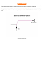
EXTERNAL S-METER
TALK BACK MODIFICATION
TONE MODIFICATION
ALIGNMENT PROCEDURES
●
●
●
●
●
●
TX Alignment
TX Alignment Locations
RX Alignment
RX Alignment Locations
PLL Alignment
PLL Alignment Locations
Este manual es una recopilación de las mejores páginas web. Radioaficion.com,.. No ofrece ninguna garantia sobre el contenido del mismo, ni se hace responsable de la
manipulación indebida de los equipos
RCI-2950 Specifications
Key Features
·Full Band Coverage - Covers the 10 Meter Amateur Band from 28.0000 to 29.6999 MHz.
·All Mode Operation - Operates on USB, LSB, CW, AM and FM.
·Brightness Control - Four Step LCD brightness control for easy viewing under any condition.
·Repeater Offset Switch - Gives you standard offsets for repeater operation.
·Programmable Frequencies - Allows you to program up to 10 individual frequencies. Includes battery backup.
·Built in Dual VFO - Choose steps of 10kHz, lkHz or 100Hz, manual or scan
·RIT - Receiver Incremental Tuning to fine tune the receive frequency up to +/- 3kHz.
·Squelch - Cuts off or eliminates receiver background noise in the absence of incoming signals.
·Noise Blanker - Greatly reduces repetitive impulse noise.
·RF Gain Control - Reduces the gain of the receiver under strong signal conditions to prevent overloading.
·RF Power Output Selector - Lets you select transmitting output power
·External Speaker Connection - Place a speaker anywhere for convenient listening.
·PA Mode - Use an external speaker for a mobile PA system.
·LCD Display - Large, easy to read backlit LCD display.
·Multi-Function LCD Meter - Indicates transmit power, receive signal strength, modulation, SWR Calibration and SWR.
Specifications
General
·Frequency Range: 28.0000~29.6999 MHz
·Tuning Steps: 100Hz, 1kHz, 10kHz, 100kHz, 1MHz
·Emission Types: USB, LSB(A3J), CW(A1), AM(A3), FM(F3)
·Frequency Control: Phase-Locked Loop Synthesizer
·Frequency Tolerance: 0.005%
·Frequency Stability: 0.001%
·Operating Temperature Range: 0 to 40 degrees C.
·Antenna Impedance: 50 Ohms
·Microphone: 400 Ohms, Dynamic PTT
·Speaker: 8 Ohms, 2 Watts
·Display: Digital Frequency, LCD
·Meter Function: RF Output, Receive Signal Strength, Modulation, SWR Calibration, SWR
·Power Requirements: 13.8 Volt DC Negative Ground
Transmitter
·Antenna Connector: UHF TYPE, 50 Ohm
·RF Transmit Modes: USB, LSB, CW, AM, FM
·RF Output Power: USB, LSB (25W); CW (8W); AM/FM (8W)
·Spurious Emissions: -50dB
·Carrier Suppression (SSB Modes): -50 dB
Receiver
·Sensitivity for 10dB SINAD: AM 0.5uV
·Sensitivity for 10dB SINAD: USB/LSB/CW 0.15uV
·Sensitivity for 12dB SINAD: FM 0.25uV
·Image Rejection Ratio: 65dB
·AGC Figure of Merit: SSB/CW/AM 80dB for 50mV for 10dB Change in Audio Output
·Audio Output Power: 2.5 Watts
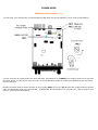
RCI-2950 Controls and Connections
INTRODUCTION
This section explains the basic operating procedures for the RCI-2950/2970 amateur 10 meter mobile transceiver.
CONTROL & CONNECTIONS
1. FREQUENCY SELECTOR:
This control is used to select a desired transmit and receive frequency. It enables you to make a continuous tuning over the entire
range of the transceiver.
2. RF POWER CONTROL:
This control enables you to adjust RF power continuously over the range of 1 watt through 25 watts
(RCI-2970: 10 watts through 100 watts).
3. MIC GAIN CONTROL:
This control adjusts the microphone gain in the transmit and PA modes. This feature is designed for use in a
h-ambient noise environment or to maxize talk power.
4. ON/OFF VOLUME CONTROL:
Turn clockwise to apply power to the radio and to set the desired listening level.
5. SQUELCH CONTROL:
This control is used to control or eliminate receiver background noise in the absence of an incoming signal.
For maximum receiver sensitivity, it is desired that the control be adjusted only to the point where the receiver background noise
is eliminated. Turn fully counterclockwise then slowly turn clockwise until the receiver noise disappears. Any signal to be received
must now be slightly stronger than the average received noise. Further clockwise rotation will increase the threshold level which a
signal must overcome in order to be heard. Only strong signals will be heard at a maximum clockwise setting.
6. RF GAIN CONTROL:
This control is used to reduce the gain of the RF amplifier under strong conditions.
7. CLARIFIER CONTROL:
This control is used to fine tune the received signal for the maximum clarity in SSB or OW mode. It can adjust
the receive frequency about + / - 500 Hz, but does not affect the transmit frequency or the frequency display.
8. MODE SWITCH:
This switch allows you to select one of the six following operating modes: FM, AM, USB, LSB, CW, and PA.
9. NB/ANL BUTTON:
The noise blanker is very effective in eliminating repetitive impulse noise such as ignition interference. In the ANL position, the automatic noise limiter in the audio circuits is activated.
10. ROGER BEEP BUTTON:
This button activates the ROGER BEEP Circuit when its function is selected.
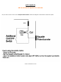
11. SPLIT BUTTON:
This control enables you to split an operating frequency for FM Repeater operation.
12. PROGRAM BUTTON:
This button is used to program operating or scanning frequencies into memory. See the OPERATION section of the manual for
further details.
13. MANUAL BUTTON:
This is used to return the unit to manual mode.
14. SHIFT BUTTON:
This is used to select 100Hz, 1kHz, 10kHz, 100kHz or 1MHz frequency steps.
15. DIM BUTTON:
This button adjusts the display backlighting in four different steps to best match the environment.
16. SWR BUTTON:
This control is used to check SWR.
17. SCAN BUTTON:
This is used to scan frequencies in each band segment. The OPERATION segment of this manual provides
detailed information on using the SCAN control.
18. MEMORY BUTTON:
This button is used to program memory channels. Detailed information on how to use this control is provided in the OPERATION
section of this manual.
19. ENTER BUTTON:
This is used to program frequencies in memory. See the OPERATION section of this manual for more information on using this
control.
20. LOCK BUTTON :
This button is used to lock a selected frequency. Press it activate the switch. In this position, it disables the Frequency Selector
Control, up/down buttons on the front control panel, or remote up/down buttons on the microphone. Repressing the switch will
unlock the frequency.
21. UP/DOWN SELECTORS:
These buttons are used to move frequency upward or downward to select a desired frequency.
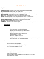
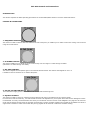
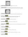
22. METER:
This meter indicates received signal strength, transmitter RF output power and SWR level.
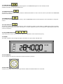
23. LCD DISPLAY:
The LCD displays the frequency selected, functions and memory channel.
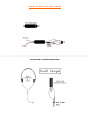
24. MIC JACK:
Accepts 6 pin female connector with a type Philmore T6160 and Calrad 30445 to be connected.
INTRODUCTION
This section explains the basic programming procedures for the RCI-2950/2970 amateur 10 meter mobile transceiver.
FREQUENCY SELECTION
Frequency selection in the RCI-2950/2970 can be accomplished using three of the following methods:
1. The first method of frequency selection is through the use of the
arrows. To accomplish this, press the
(Shift) key and the
and
button until the cursor arrow is positioned under the digit of the frequency that
arrow to increase the number. If a decrease in frequency is desired, press the
is to be changed. Then use the
arrow. Perform the steps described above for each digit of the frequency until the desired frequency is dispIayed in
the LCD display window.
2. The second method of frequency selection is accomplished using the
button and the frequency select knob located
above the microphone jack. Use the SHF button in the manner described above to select the digit to
be changed. Then proceed to rotate the frequency select knob clockwise to increase the frequency. Rotate the frequency select
knob counterclockwise to decrease the frequency.
3. The third method of selecting the operating frequency of the radio is through the use of the
button and the channel
Up and Down button located on the microphone Frequency selection by this method is accomplished in the same manner as with
and
the
microphone are used.
arrows on the key pad. The only difference is that the channel Up and Down buttons on the
While in receive mode, once a signal has been detected on a particular frequency, it may be necessary to slightly change the
frequency to provide the best audio through the speaker. This can be accomplished by rotating the clarifier control to vary the
frequency by ± 0.5 kHz. After this fine tuning has been accomplished, press the
point of best reception.
button to lock in the frequency at the
FREQUENCY SCANNING
Frequency scanning can be achieved using one of two methods: the first method involves the scanning of pre-programmed
memory channels; the second method will permit the user to scan all frequencies between a preset upper and lower scan limit.
Both methods of frequency scanning follow.
All Frequency Scanning
To allow All Frequency Scanning, one must first program the upper and lower scanning limits. The scan limits are simply the
highest and lowest frequencies that will be scanned. To program these limits, perform the following steps:
1. Press the
(Program) key.
2. Press the
key. (“PRG SCAN+” should appear in the lower right corner of the display window.
3. Using the
key and the
and
4. Press the
key again. (“SCAN -“ should appear in the display window.)
5. Using the
key and the
and
arrows, select the upper scan limit, then press
arrows, select the lower scan limit, then press
.
.
The upper and lower scan limits have now been programmed. To activate the scan feature, return the radio to manual operation
button. If the display shows ‘SCAN the radio will scan from the lower limit to the upper limit. If “SCAN -‘
and press the
is displayed, the unit will scan from the upper limit to the lower limit. To change from SCAN + to SCAN - or vice versa, press
.
NOTE: When programmed, the upper and lower scan limits will also act as the upper and lower operating limits of the radio. The
radio cannot now be programmed to operate above or below the scan limits.
Memory Scanning
The RCI-295012970 has 10 non-volatile (i.e* memory resident) memory locations which can be programmed with any available
frequency within the operating band of the radio. The scan function of the unit can be programmed to scan these memory
channels. The radio will then scan only those memory channels which have been programmed.
The first step in utilizing the memory scan function is to program the desired frequencies into the radio memory. This can be
accomplished by performing the following steps:
1. With the radio operating in the manual mode, press the
(Program) key.
2. Press the
(Memory) key. “PRG” should be displayed in the lower right-hand corner of the LCD display window. In
the upper left portion of the display, “MEMORY” should be displayed. Directly below MEMORY, a number between 0 and 9 will be
displayed. This number represents the memory location currently being displayed. Pressing the
memory counter to the next memory location and the contents of that memory location will be displayed.
3. Using the
key and the
and
key will increase the
arrows, enter the frequency to be stored in the memory
location displayed. After the desired frequency has been entered, press
.
4. Repeat steps 2 and 3 for all of the memory locations to be programmed.
5. After all desired memory locations have been programmed with frequencies, return the unit to the manual mode of operation by
pressing the
key.
6. To initiate memory scanning, press
and then press
. As previously discussed, the display will show
“SCAN + “ or “SCAN -“ to indicate whether the radi0 is scanning from the lowest or the highest merory location or vice versa.
7. To return the radio to normal (non-scanning) operation, press the
key.
OFFSET FREQ. OPERATION
The RCI-2950/2970 has an offset or split frequency feature that will permit the radio to be operated in a half-duplex mode This
will allow the user to talk on FM repeaters operating in the 10 Meter band. (NOTE The FM repeaters may require a sub-audible
(CTCSS) tone be transmitted to gain access to the repeater. The RCI-2950 is not factory-equipped with a CTCSS encoder/
decoder.) The split frequency function offsets the transmitter frequency either above or below the receive frequency by a user
programmable amount. In the following example, programming of a 100kHz offset will be described. Before attempting to program
the offset frequency, ensure that the radio is operating in the manual mode by pressing the
key.
1. Press the
key.
2. Press the
left-hand corner.
key. The LCD display window will display “00000” with “PRG” and “SPLIT” being displayed in the lower
3. Using the
“010000.”
key and the
4. Press
and
. A 100kHz offset has now been programmed into the radio.
5. Return the radio to manual operation by pressing the
6. Using the
receive frequency.
arrows as described earlier, program the display to read
key and the
and
key.
arrows as described previously, set the radio for the desired
7. Press
. In the lower right corner of the display, either “SPLIT + “or “SPLIT -“ will be displayed. If SPLIT + is
displayed, the transmitter will be offset 100kHz above the receive frequency when keyed. If SPLIT - is displayed, the transmitter
will be offset 100kHz below the receive frequency.
9. NOTE: When the transmitter Is keyed, the frequency display will change to show the frequency being transmitted.
8. To return the radio to simplex operation (i.e, same transmit and receive frequency), press the
key.
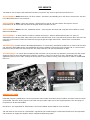
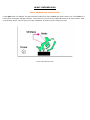
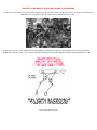
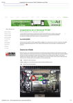
Technical Analysis of the RCI 2950, RCI 2970, RCI 2990, Saturn Turbo circuitry
The first striking element of the RCI is the complex frequency synthesizer. As most of the CB rigs use a + 10 Khz
step , the RCI uses a 100 times thinner 100 Hz step.
The brain of the RCI is the Microprocessor. The microprocessor is hold by the small board located behind the LCD
display. This board rules the rig. It is a double sided board which holds a battery, an alignment of 2.54mm
connectors, a voltage regulator (5V - MC7805) on its back. The regulator feeds all the digital components, a
network of internal resistors. On the same side of the board, you can find a buzzer and a lithium battery which is
here to keep the memories when the rig is switched off. Note that, in the latest versions of RCI rigs, the lithium
battery has been replaced by a capacitor.
The other side of the board holds 3 CMS chips, a double Op-Amp (5223), a box containing 6 inversors gates
(buffers) CD4069. This last one is controlling the 6 digits of the display. This side of the board also holds a 64
pins CMS chip, driven at 4 Mhz by a crystal, which is a CMOS circuit. It owns a ROM of 2 K, Four 4 bits registers,
a 8 bit timer, a serial 8 bits communication interface, 24 Input/Output. Everything is controlled by 10
microseconds cycles. A controller-Driver of Liquid Display Boards is supervising all the needed display cycles on
the 24 lines of the LCD segments to display the 6 numbers (7 segments by number) on the orange screen. The
microprocessor is having very low consumption characteristics: less than 900 µA.
The programming of the microprocessor is done at factory. All the functions and the frequencies range are
stored into the ROM. A jumper allows us to change the frequency range. All the main informations are send to
the frequency synthesizer by a limited amount of links: clock signals (CLK), transfers (LAT), serial data (DATA).
All these informations are not given by the schematic diagram but were useful to know. Let's pay a visit to the
main board.
The Frequency Synthesizer is complex because of the 100 Hz resolution. It owns a dozen of integrated
circuits: a programmable divider (IC17:7925 Sony) addressed in serial mode by the microprocessor, a first VCO
(IC8: TA7310 Toshiba), two phase comparers (IC5-IC7 TC5081 Toshiba), three mixers (IC9-IC10-IC14:
TA7310), an oscillator-divider driven by a 10.250 Mhz crystal. This part of the rig generates 2 different
frequencies: in RC mode to get an infradyne pulse of the first conversion (RX QRG - Interm.QRG of 10.695 Mhz)
and in TX, the necessary to produce a supradyne ( Interm.QRG of 10.695Mhz + FVCO). Depending of the TX
mode, in AM/FM, the Q44 oscillator is controlled by X3 (10.695 Mhz). In SSB and CW, there is a 1500 Hz jump
(+ 1500 Hz in USB and CW and -1500 Hz in LSB).
The transmit circuits follow the frequency synthesizer. It has a HF mixer (IC20 : SO42P Siemens). It is
adapted in large band conditions by a set of varicaps D93-D94-D95. The result of the mixing is then applied to a
band filter (L43-L46), amplifier in voltage by a transistor Q50: 2SC1730L. The output level of this TR is enough
to control the pre-driver (Q49: 2SC1973). The pre-driver, via L41, excites two finals in parallel (Q46-Q47:
2SC2312). They are followed by a low-pass filter in PI (L32-L31) and associated capacitors C243-247-251).. And
then a hi-pass filter follows (L33/C248-VC3). A line of measurement of the SWR is present in the form of a
vertical mini circuitry board, plugged between the TX output and the antenna plug. All the 3 power transistors
are biased VR11. In AM and FM, the mixer IC20 adds the VCO QRG to 10.695 (Q44). In SSB and CW, it is the
output of the crystal filter that is added.
The receiver is classical: superheterodyne with 2 IF conversions. It is very similar to the one of most cb rigs.
There are output stages: HF Amp (Q18: 2SC1674), transfo L8, first mixer Q19: 310), L9-L11 filter, the IF output
by L12,L13,L14. What strikes is the presence of varicaps D19,D23,D24 which works to produce a perfect tune in
this large band rig. The band filtering is also perfect. It is done by two combined transfos linking the HF amp to
the mixer. The ceramic IF filter FL2: 10.995 Mhz is attacked by L14. The a second stage of IF Q8 is feeding the
second IF filter FL3 455 Khz. The first following TR loads Q5. Then Q10 & Q11 produce a Hugh gain before the
first IF transfo L6. The follow AM and FM demodulators. In AM you have a diode circuit to detect and gain control
(D11-D12). The Op-Amp IC1: LM324 follows. IC2, is the discriminator (UPC1028H). It handles the FM.
In SSB, the signal from the first mixer is bandwidth reduced by FL3 then applied to the first amplification IF
stage Q20. A high gain amp follows Q21-Q22-Q23. The audio output is controlled by a classical audio amp IC19
(TA7222P)
The noise blanker is very good. It is composed of 6 stages with at least 7 TR and 3 diodes assuming the
amplification of HF interference coming from the first QRG changer.
The AM is using a classical and reliable technology: a ballast PNP transistor (Q51).
In FM, we can find the old good MC14558P (IC16) which handles modulation of the mike before exciting the
varicap of the VCO to produce frequency excursions.
In SSB, IC16 pre-amplifies the mike signals. It is followed by IC3 (AN612) which produces a double side band
modulation (DSB). Once going through the crystal filter, the un-wanted side band is eliminated.
You now know more about the hiddent componentes of your RIG.
www.radioaficion.com
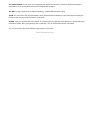
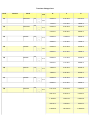
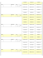
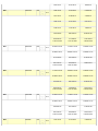
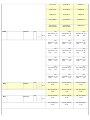
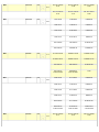
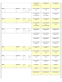
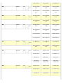
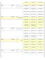
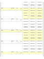
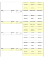
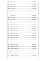
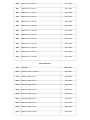
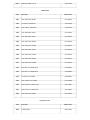
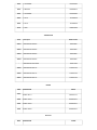
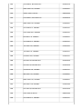
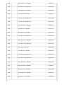
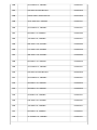
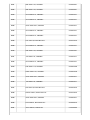
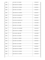
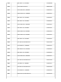
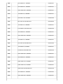
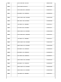
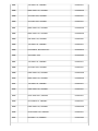
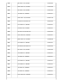
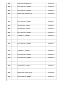
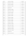
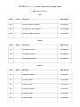
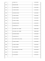
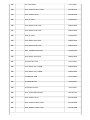
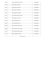
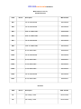
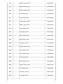
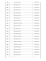
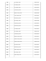
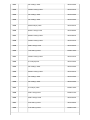
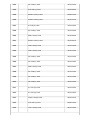
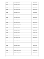
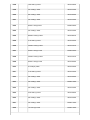
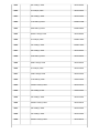
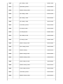
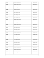
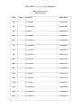
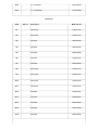
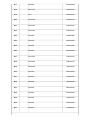
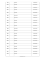
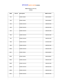
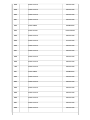
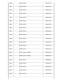
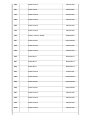
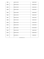
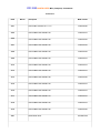
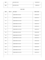
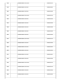
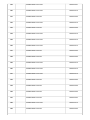
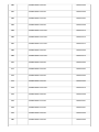
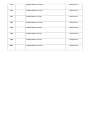
Transistor Voltage Chart
Ref #
Function
Part #
B
C
E
0.00NB Off
0.00 NB Off
0.00 NB Off
1.77NB On
7.67 NB On
1.06NB On
0.00NB Off
0.00 NB Off
0.00NB Off
0.71NB On
2.09 NB On
0.00NB On
0.00NB Off
0.00NB Off
0.00NB Off
2.09NB On
7.76 NB On
1.45NB On
0.00NB Off
8.01 NB Off
0.01NB Off
0.02NB On
8.01 NB On
1.06NB On
0.00NB Off
7.37 NB Off
0.01NB Off
0.01NB On
7.37 NB On
0.03NB On
7.36NB Off
0.00 NB Off
8.01NB Off
7.36NB On
0.00 NB On
8.01NB On
0.00NB Off
0.00 NB Off
0.00NB Off
0.00NB On
0.01 NB On
0.00NB On
1.18 AM RX
6.93 AM RX
0.48AM RX
0.02 AM TX
0.03 AM TX
2.44AM TX
1.18FM RX
6.93FM RX
0.48FM RX
0.01FM TX
0.02FM TX
2.44FM TX
1.30SSB RX
7.60 SSB RX
2.38SSB RX
LOC
Q1
2SC1675L
NPN
B-3
Q2
2SC1675L
NPN
C-2
Q3
2SC945
NPN
C-3
Q4
2SC945
NPN
B-2
Q5
2SC945
NPN
C-3
Q6
2SA733
PNP
C-2
Q7
2SC945
NPN
C-2
Q8
2SC1674
NPN
D-2
Q9
2SC1675
NPN
0.01SSB TX
0.02 SSB TX
2.44SSB TX
0.71AM / FM RX
3.04AM / FM RX
0.00AM / FM RX
0.01AM / FM TX
0.03AM / FM TX
0.00AM / FM TX
0.82 SSB RX
0.03 SSB RX
0.00SSB RX
0.81SSB TX
0.02 SSB TX
0.00SSB TX
3.03AM /FM RX
5.76AM / FM RX
2.26AM / FM RX
0.02AM / FM TX
0.02AM / FM TX
0.01AM / FM TX
0.03SSB RX
8.02 SSB RX
0.00SSB RX
0.02SSB TX
0.02 SSB TX
0.01SSB TX
2.26AM / FM RX
5.49AM / FM RX
1.52AM / FM RX
0.01AM / FM TX
0.02AM / FM TX
0.01AM / FM TX
0.00 SSB RX
8.02 SSB RX
0.01SSB RX
0.01 SSB TX
0.02 SSB TX
0.01SSB TX
8.02NB Off
0.00 NB Off
8.06NB Off
7.35NB On
8.01 NB On
8.06NB On
0.00AM / FM RX
-0.25AM / FM RX
0.00AM / FM RX
0.01AM / FM TX
-0.24AM / FM TX
0.00AM / FM TX
0.71 SSB RX
0.01 SSB RX
0.00 SSB RX
0.71 SSB TX
0.01 SSB TX
0.00SSB TX
0.70AM / FM RX
0.01AM / FM RX
0.00AM / FM RX
0.71AM / FM TX
0.02AM / FM TX
0.00AM / FM TX
D-3
Q10
2SC1675
NPN
D-4
Q11
2SC1675L
NPN
D-4
Q12
2SA733
PNP
B-4
Q13
2SC945
NPN
B-4
Q14
2SC945
NPN
B-4
Q15
2SC945
NPN
0.01 SSB RX
0.11 SSB RX
0.00 SSB RX
0.01SSB TX
0.01 SSB TX
0.00SSB TX
0.01AM / FM RX
0.02AM / FM RX
0.00AM / FM RX
0.01AM / FM TX
0.01AM / FM TX
0.00AM / FM TX
0.70 SSB RX
0.01 SSB RX
0.00 SSB RX
0.71SSB TX
0.01 SSB TX
0.00SSB TX
1.26AM / FM RX
5.04AM / FM RX
0.68AM / FM RX
1.26AM / FM TX
5.05AM / FM TX
0.68AM / FM TX
1.26 SSB RX
5.01 SSB RX
0.68 SSB RX
1.26SSB TX
5.01 SSB TX
0.68SSB TX
0.00AM / FM RX
0-0.01AM / FM RX
0.00AM / FM RX
0.76 SSB TX
0.02 SSB TX
0.00SSB TX
2.15 AM RX
7.73 AM RX
1.41AM RX
0.02 AM TX
0.03 AM TX
0.01AM TX
2.15 FM RX
7.73 FM RX
1.41FM RX
0.03 FM TX
0.08 FM TX
0.01FM TX
2.16 SSB RX
7.74 SSB RX
1.41 SSB RX
0.01 SSB TX
0.02 SSB TX
0.01SSB TX
0.03AM / SSB RX
7.95AM / SSB RX
1.89AM / SSB RX
0.01AM / SSB TX
0.02AM / SSB TX
0.03AM / SSB TX
0.00 FM RX
7.95 FM RX
1.90FM RX
E-4
Q16
2SC945
NPN
E-5
Q17
2SC945
NPN
B-2
Q18
2SC1674
NPN
C-2
Q19
J310
FET
D-3
Q20
2SC1674
NPN
0.01 FM TX
0.07 FM TX
0.07FM TX
0.95 AM RX
0.24 AM RX
0.23AM RX
3.41 AM TX
3.02 AM TX
7.34AM TX
0.95 FM RX
0.24 FM RX
0.23 FM RX
1.66 FM TX
1.19 FM TX
7.35FM TX
1.60 SSB RX
6.69 SSB RX
0.85 SSB RX
3.40 SSB TX
3.42 With MOD
7.11 SSB TX
7.13 With MOD
7.34 SSB TX
7.36 With MOD
0.22AM / FM RX
1.74AM / FM RX
0.00AM / FM RX
0.02AM / FM TX
0.03AM / FM TX
0.00AM / FM TX
0.73 SSB RX
3.43 SSB RX
0.00 SSB RX
0.01 SSB TX
0.03 With MOD
0.02 SSB TX
0.04 With MOD
0.00 SSB TX
1.74AM / FM RX
0.93AM / FM RX
0.92AM / FM RX
0.03AM / FM TX
0.40AM / FM TX
0.02AM / FM TX
3.43 SSB RX
6.52 SSB RX
2.66 SSB RX
0.02 SSB TX
0.04 With MOD
7.09 SSB TX
7.16 With MOD
0.01 SSB TX
0.03 With MOD
3.92AM / FM RX
7.78AM / FM RX
0.23AM / FM RX
0.02AM / FM TX
0.02AM / FM TX
0.02AM / FM TX
2.65 SSB RX
6.10 SSB RX
1.90 SSB RX
0.01 SSB TX
0.02 With MOD
0.02 SSB TX
0.04 With MOD
0.01 SSB TX
0.03 With MOD
0.70 AM RX
0.01 AM RX
0.00AM RX
D-4
Q21
2SC1675
NPN
D-4
Q22
2SC1675
NPN
D-4
Q23
2SC1906
NPN
D-4
Q24
2SC945
NPN
D-2
TR25
2SA733
0.71 AM TX
0.02 AM TX
0.00AM TX
0.01 FM RX
0.18 FM RX
0.00FM RX
0.02 FM TX
0.05 FM TX
0.00FM TX
0.01 SSB RX
0.01 SSB RX
0.00 SSB RX
0.01 SSB TX
0.03 With MOD
0.02 SSB TX
0.20 With MOD
0.00 SSB TX
PNP
ANL
D-1
8.01 AM RX ON
6.72
OFF
ANL
0.16 AM RX ON
7.38
OFF
ANL
8.02 AM TX ON
6.73
OFF
ANL
0.22 AM TX ON
7.38
OFF
ANL
0.01 FM RX ON
0.01
OFF
2SC945
NPN
D-1
Q27
2SC1675
NPN
C-5
ANL
0.02 FM TX ON
0.02
OFF
ANL
0.01 SSB RX ON
0.01
OFF
ANL
Q26
ANL
0.01 FM RX ON
0.01
OFF
ANL
0.02 FM TX ON
0.02
OFF
ANL
0.01 SSB RX ON
0.01
OFF
ANL
8.06 AM TX ON
7.39
OFF
ANL
0.01 FM RX ON
0.01
OFF
ANL
0.02 FM TX ON
0.02
OFF
ANL
8.05 AM RX ON
7.38
OFF
ANL
0.01 SSB RX ON
0.01
OFF
ANL
ANL
0.02 SSB TX ON
0.02
OFF
0.01 SSB TX ON
0.01
OFF
0.01 SSB TX ON
0.01
OFF
AM / FM / SSB RX
AM / FM / SSB RX
AM / FM / SSB RX
2.82
7.19
2.28
AM / FM / SSB TX
AM / FM / SSB TX
AM / FM / SSB TX
2.84
7.20
2.29
AM / FM / SSB RX
AM / FM / SSB RX
AM / FM / SSB RX
3.44
5.93
2.70
AM / FM / SSB TX
AM / FM / SSB TX
AM / FM / SSB TX
3.45
5.94
2.71
Q28
2SC1675
NPN
D-4
Q29
2SC1675
NPN
AM / FM / SSB RX
AM / FM / SSB RX
AM / FM / SSB RX
0.72
4.36
0.00
AM / FM / SSB TX
AM / FM / SSB TX
AM / FM / SSB TX
0.72
4.37
0.00
0.01 AM RX
7.95 AM RX
0.00AM RX
0.02 AM TX
7.96 AM TX
0.00AM TX
0.75 FM RX
0.02 FM RX
0.00FM RX
0.79 FM TX
0.07 FM TX
0.00FM TX
0.01 SSB RX
7.94 SSB RX
0.00 SSB RX
0.01 SSB TX
7.95 SSB TX
0.00SSB TX
0.71AM / FM RX
0.02AM / FM RX
0.00AM / FM RX
0.72AM / FM TX
0.03AM / FM TX
0.00AM / FM TX
0.01 SSB RX
2.95 SSB RX
0.00 SSB RX
0.01 SSB TX
0.03 With MOD
2.89 SSB TX
2.91 With MOD
0.00
8.02 AM RX
0.11 AM RX
8.06AM RX
8.02 AM TX
-0.34 AM TX
8.06AM TX
8.02 FM RX
0.11 FM RX
8.06FM RX
8.02 FM TX
-0.39 FM TX
8.06FM TX
8.02 SSB RX
-0.11 SSB RX
8.06 SSB RX
8.02 SSB TX
6.95 With MOD
-0.43 SSB TX
5.46 With MOD
8.05 SSB TX
7.57 With MOD
AM / FM / SSB RX
AM / FM / SSB RX
AM / FM / SSB RX
0.71
0.01
0.00
E-6
Q30
2SC945
NPN
F-1
Q31
2SA733
PNP
B-3
Q32
2SA945
NPN
F-6
AM / FM / SSB TX
AM / FM / SSB TX
AM / FM / SSB TX
0.01
0.01
0.00
AM / FM / SSB RX
AM / FM / SSB RX
AM / FM / SSB RX
0.24
0.25
0.00
AM / FM / SSB TX
AM / FM / SSB TX
AM / FM / SSB TX
0.57
0.72
0.00
0.58 SSB MOD
0.74 SSB MOD
AM / FM / SSB RX
AM / FM / SSB RX
AM / FM / SSB RX
0.00
1.32
0.00
AM / FM / SSB TX
AM / FM / SSB TX
AM / FM / SSB TX
0.00
0.01
0.00
0.01 SSB MOD
0.94 AM/SSB MOD
AM / FM / SSB RX
8.02R.B. Off
AM / FM / SSB RX
3.05R.B. Off
AM / FM / SSB RX
8.06R.B. Off
AM / FM / SSB TX
8.03R.B. Off
AM / FM / SSB TX
-0.70R.B. Off
AM / FM / SSB TX
8.07R.B. On
AM / FM / SSB RX
7.41R.B. On
AM / FM / SSB RX
8.05R.B. On
AM / FM / SSB RX
8.06R.B. On
AM / FM / SSB TX
7.42R.B. On
AM / FM / SSB TX
8.06R.B. On
AM / FM / SSB TX
8.07R.B. On
AM / FM / SSB RX
AM / FM / SSB RX
AM / FM / SSB RX
0.01
8.03
0.01
AM / FM / SSB TX
AM / FM / SSB TX
AM / FM / SSB TX
0.02
8.04
0.35
AM / FM / SSB RX
AM / FM / SSB RX
AM / FM / SSB RX
7.36
0.02
8.06
AM / FM / SSB TX
AM / FM / SSB TX
AM / FM / SSB TX
8.05
8.04
0.35
8.02AM RX
0.00AM RX
8.06AM RX
7.27AM TX
7.95AM TX
8.05AM TX
8.02 FM/SSB RX
0.00 FM/SSB RX
8.06 FM/SSB RX
0.50 With MOD
Q33
2SC945
NPN
E-6
Q34
2SC945
NPN
F-6
Q35
2SA733
PNP
C-5
Q36
2SC945
NPN
C-6
Q37
2SA1282
PNP
D-6
Q38
2SA1282
PNP
C-6
Q39
2SC945
NPN
A-2
Q40
2SA1282
PNP
A-1
Q41
2SC945
NPN
B-1
Q42
2SC945
NPN
B-1
Q43
2SC1675
NPN
7.28 FM/SSB TX
7.96 FM/SSB TX
8.04FM/SSB TX
AM / FM / SSB RX
AM / FM / SSB RX
AM / FM / SSB RX
0.63
0.05
0.00
AM / FM / SSB TX
AM / FM / SSB TX
AM / FM / SSB TX
0.01
8.04
0.00
AM / FM / SSB RX
AM / FM / SSB RX
AM / FM / SSB RX
7.54
0.28
8.05
AM / FM / SSB TX
AM / FM / SSB TX
AM / FM / SSB TX
7.35
8.04
8.06
AM / FM / SSB RX
AM / FM / SSB RX
AM / FM / SSB RX
0.00
0.29
0.00
AM / FM / SSB TX
AM / FM / SSB TX
AM / FM / SSB TX
0.01
3.15
0.00
0.70 CW Mode RX
0.01 CW Mode RX
0.00CW Mode RX
0.71 CW Mode TX
0.02 CW Mode TX
0.00CW Mode TX
AM / FM / SSB RX
AM / FM / SSB RX
AM / FM / SSB RX
0.77
1.65
0.15
AM / FM / SSB TX
AM / FM / SSB TX
AM / FM / SSB TX
0.78
1.65
0.16
0.00AM / FM RX
8.04AM / FM RX
5.06AM / FM RX
0.01AM / FM TX
8.04AM / FM TX
5.05AM / FM TX
0.00 SSB RX
8.04 SSB RX
0.30 SSB RX
0.01 SSB TX
0.07 With MOD
8.04 SSB TX
5.60 With MOD
0.30 SSB TX
1.05 With MOD
0.02AM / FM RX
0.03AM / FM RX
0.01AM / FM RX
2.12AM / FM TX
4.56AM / FM TX
1.41AM / FM TX
2.10 SSB RX
4.54 SSB RX
1.38 SSB RX
B-3
Q44
2SC1675
NPN
B-6
Q45
2SA733
PNP
B-6
Q46
2SC2312
NPN
2.12 SSB TX
4.57 SSB TX
1.40 SSB TX
AM / FM / SSB RX
AM / FM / SSB RX
AM / FM / SSB RX
8.04
0.01
0.00
AM / FM / SSB TX
AM / FM / SSB TX
AM / FM / SSB TX
8.05
0.02
0.01
8.04 CW Mode RX
0.00 CW Mode RX
8.04CW Mode RX
4.91 CW Mode TX
5.54 CW Mode TX
5.58CW Mode TX
0.00AM / FM RX
4.15AM / FM RX
0.00AM / FM RX
0.68AM / FM TX
3.80AM / FM TX
0.00AM / FM TX
0.00 SSB RX
13.25 SSB RX
0.00 SSB RX
0.68 SSB TX
0.71 With MOD
12.60 SSB TX
15.11 With MOD
0.00
0.00AM / FM RX
4.15AM / FM RX
0.00AM / FM RX
0.58AM / FM TX
3.80AM / FM TX
0.00AM / FM TX
0.00 SSB RX
13.25 SSB RX
0.00 SSB RX
0.68 SSB TX
0.71 With MOD
12.60 SSB TX
15.11 With MOD
0.00
0.00AM / FM RX
4.15AM / FM RX
0.00AM / FM RX
0.74AM / FM TX
3.88AM / FM TX
0.00AM / FM TX
0.00 SSB RX
13.25 SSB RX
0.00 SSB RX
0.74 SSB TX
12.75 SSB TX
0.00
0.00AM / FM RX
0.00AM / FM RX
0.00AM / FM RX
1.25 AM / FM TX
8.30AM / FM TX
0.70AM / FM TX
B-6
Q47
2SC2312
NPN
A-6
Q48
2SC2166
NPN
B-4
Q49
2SC2314
NPN
B-4
Q50
2SC1906
NPN
0.00 SSB RX
0.00 SSB RX
0.00 SSB RX
1.28 SSB TX
1.30 With MOD
7.95 SSB TX
8.06 With MOD
0.57 SSB TX
0.59 With MOD
0.00AM / FM RX
0.00AM / FM RX
0.00AM / FM RX
1.41AM / FM TX
7.95AM / FM TX
0.71AM / FM TX
0.00 SSB RX
0.00 SSB RX
0.00 SSB RX
1.45 SSB TX
7.95 SSB TX
7.97 With MOD
0.66 SSB TX
0.69 With MOD
13.31AM / FM RX
4.29 AM / FM RX
13.79AM / FM RX
12.74AM / FM TX
3.43AM / FM TX
13.57AM / FM TX
13.25 SSB RX
13.25 SSB RX
13.79 SSB RX
12.80 SSB TX
12.15 With MOD
12.80 SSB TX
12.13 With MOD
13.66 SSB TX
13.39 With MOD
4.03AM / FM RX
13.30AM / FM RX
4.10AM / FM RX
4.03AM / FM TX
12.15AM / FM TX
3.48AM / FM TX
12.27 SSB RX
12.63 SSB RX
12.85 SSB RX
11.75 SSB TX
11.23 With MOD
12.30 SSB TX
11.52 With MOD
12.55 SSB TX
11.79 With MOD
13.30AM / FM RX
4.29AM / FM RX
13.31AM / FM RX
12.15AM / FM TX
3.43AM / FM TX
12.74AM / FM TX
12.63 SSB RX
13.25 SSB RX
13.25 SSB RX
12.30 SSB TX
11.52 With MOD
12.80 SSB TX
12.13 With MOD
12.80 SSB TX
12.15 With MOD
0.00 AM / FM RX
13.30AM / FM RX
0.00AM / FM RX
B-4
Q51
2SB754
PNP
B-4
Q52
2SC945
NPN
B-4
Q53
2SA473
PNP
B-4
Q54
2SC945
NPN
B-4
Q55
2SC945
NPN
0.02 AM / FM TX
12.18AM / FM TX
0.00AM / FM TX
0.73 SSB RX
0.05 SSB RX
0.00 SSB RX
0.73 SSB TX
0.75 With MOD
0.05 SSB TX
0.07 With MOD
0.00 SSB TX
0.63AM / FM RX
8.05AM / FM RX
0.53 AM / FM RX
0.64 AM / FM TX
8.05AM / FM TX
0.43AM / FM TX
0.63 SSB RX
8.05 SSB RX
1.65 SSB RX
0.63 SSB TX
0.63 With MOD
8.05 SSB TX
6.90 With MOD
0.63 SSB TX
0.63 With MOD
0.71AM / FM RX
0.01AM / FM RX
0.00AM / FM RX
0.72 AM / FM TX
0.02AM / FM TX
0.00AM / FM TX
0.71 SSB RX
0.01SSB RX
0.00 SSB RX
0.71 SSB TX
0.73 With MOD
0.01 SSB TX
0.03 With MOD
0.00 SSB TX
0.69 AM RX
0.02 AM RX
0.00 AM RX
0.70 AM TX
0.03 AM TX
0.00 AM TX
0.00 FM RX
0.71 FM RX
0.00 FM RX
0.02 FM TX
0.72 FM TX
0.00 FM TX
0.00 SSB RX
0.71 SSB RX
0.00 SSB RX
0.01 SSB TX
0.03 With MOD
0.72 SSB TX
0.73 With MOD
0.00 SSB TX
0.01 AM RX
0.01 AM RX
0.01 AM RX
0.02 AM TX
0.02 AM TX
0.02 AM TX
1.02 FM RX
4.32 FM RX
0.38 FM RX
B-4
Q56
2SC945
NPN
B-4
Q57
2SC945
NPN
B-4
Q58
2SC945
NPN
B-4
1.03 FM TX
4.32 FM TX
0.40FM TX
0.01 SSB RX
0.01 SSB RX
0.01 SSB RX
0.01 SSB RX
0.01 SSB RX
0.01 SSB RX
www.radioaficion.com
RCI SECRETS
Just want to toss a couple radio mods and secrets to You,and if any are fit to print-then please do so!!!
#1-RCI-2950>> R247 should be a 4.7k ohm resistor...the factory accidentally put in 47k ohm in some units...this will
hurt LSB performance if not corrected....
#2-RCI-2950>> R78 is a 2.2k ohm resistor...changing this to a 6.8k 1/4 watt resistor will improve receiver
performance in all modes,and help with the RF gain control operation as well
#3-RCI-2950>> R291 is the A.M. modulation limiter...removing this will boost A.M. only,and will not affect or cause
SSB overmodulation...
#4-RCI-2950>> To allow clarifier to slide in transmit and receive...Remove D59 and R197,take a 5" piece of
INSULATED wire and strip both ends,connect one end to the LEFT hole of the removed R197,connect other end to the far
right hole of the unused 4 hole box located to the right of Q33 and right behind D75...solder these 2 connections
carefully!!!
#6-Galaxy Rigs (models with the EPT360014B boards)>>To boost A.M. modulation,do NOT cut or remove TR-32!!!This
can adversely affect SSB,causing overmodulation and severe splatter!!!!The proper way to boost A.M.,is cut one end of
R249,and remove TR53 from the board..this will really boost the A.M.,but has NO affect on SSB..
#7-Galaxy Rigs>> A certain Service Manual(I will not name it as to prevent any lawsuits!!),incorrectly lists the proper
alignment cans for A.M. and SSB center frequency operation...Can L19 is the A.M. RX freq. adjustment,L20 is USB
adjustment,and L21 is for LSB...turning the wrong cans in that cluster of tuning cans will prove to make for a REAL BAD
DAY!!!!!!!
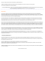
RANGER RCI-2950
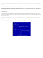
Extended Frequency Modification: On microprocessor board locate the double two pin headers and shunt near the center
of the board. Move the shunt jumper to the other two-pin header right next to the original position. The new range of
frequencies is 26.000-29.700Mhz.
D87 & D111 are responsible for FM deviation. 10uF was installed across R308 for more deviation.
J54 was used as of a source for a transmit B+ signal that was routed through a small choke and then to the output SO239 connector to supply the amplifier with a multiplexed RF/keying signal.
A 5V dip relay was used and the coil powered from the anode of D107 to allow a parallel combination of 3300uF and
47/2W resistor to be switched into series with the two final output transistors in the AM mode only. This produced an AM
swing from 100mW to about 4.5W
COMPARED
There is a big difference between the RCI 2990/Galaxy Saturn Turbo and the Galaxy Saturn.
The Galaxy Saturn is a Galaxy DX-88 in a box with 2 meters and a power supply. The frequency stabily in the Galaxy
Saturn, as with most other Galaxies, isn't the best.
The Galaxy Saturn _Turbo_ and the RCI-2990 are the same radio, albeit the different name and the Galaxy Saturn Turbo
comes with CB band enabled.
I have a Turbo and my neighbor has a Saturn, and in my opinion the Turbo/2990 is much, much more radio.
The Galaxy DX-11B is much like the Turbo/2990, with more echo controls on the front.
The Galaxy DX-22B is also like the Turbo, with no linear after it (so maybe 30-40 watts or so out, versus 120+ out of the
Turbo).
AGAIN
I was looking at the am det mod upgrade for the 2950... The radio I am working on already has 1N60 diodes for
d35-d34 , is this a mod that was done at the factory?
The bullten should be rewrighten to say what #diodes are there now and what they should be replaced with.....
The problem that is manifesting itself as AM distorion ( and TX bleed) is caused by the lack of bandwith control
due to the fact of the cheap Xtal filter they use...
I improved the Am on my set by simply puting in a 0.02 Mfd NPO cap at the AM det output diode to ground...
This narrows the bandwith improves the S/NR and cuts some of the high freq audio distortion out and provides
smoothing and harmonic reduction from the AM det....
I further improved both the AM an SSB RX (and TX Bleed) by changing the Xtal IF filter... This mod will also
incress AGC cut back from sig on other ch and improve S/NR and sen on all bands....
With these mods, realginment and installing a cascade RF RX amp makes the RCI 2950 Rx decent........
www.radioaficion.com
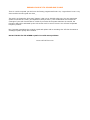
REPAIR TRICKS
FRONT END PROTECTION DIODES
These diodes go out when the radio is subject to an extremly strong input signal. If the radio doesn't recieve or quits
recieving after you unkey, check D21 & D22. These ones are 1N914 or 1N4148. They cost very few.
: Need Help.. My Galaxy's receive is almost gone! I still get some rec. but it's fading.
: It worked fine until a nearby radio keyed and then?
: Any sugestions?
On the RCI 2950 you would need to check D21 & D22. On the Galaxy Saturn after comparing the two schematics it
appears to be D33 and possibly R263 and R142. I would check these for any burning or for function.
FREQUENCY SELECTION
Frequency selection doesn't work properly. Locate R611 which is a 47 Ko resistor located on the vertical CPU board on
trace side. Change out with a 10 K quater watt resistor.
COMMON FAULTS
Older 2950's with batter backup will discarge the battery if the power source is removed and the radio is left in the "ON"
position. This causes corruption in the memory circuits and in the microprocessor. This can cause the failure to turn on....
lights on... and nothing else.
Also found other faults:
· The 8 volt regulator that is on the left side of the radio (speaker side up, front closest to you) the regulator
favors the front of the radio....anyhow... I have seen 3 or 4 radios that had the turn on with no receive or
transmit. The cause: cold solder joint on the regulator, this could be caused by the stressing of the chassis
during mobile installation or dropping, bumping of the radio. The cure: remove old solder from regulator and
resolder. Don't attempt to remove the regulator from the chassis, it's attached there for a reason... heatsink....
One other fault:
· Warbaling on ssb.... Be sure to use the proper power cord that came with the radio... don't use the radio shack
substitution. The wire guage is smaller and thus won't be able to pass enough current thru the wires. This
causes the warbaling effect on ssb. Also try turning down the mic gain on ssb when running a power mic.
· Wire the radio backwards (reverse polarity) usually causes the power regulator for AM to short out. This will
give the radio a 40 Watt carrier with no modulation. This is not to be done intentionally.... just letting you know
what the radio is able to do without power control.
www.radioaficion.com
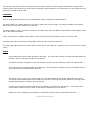
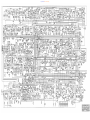
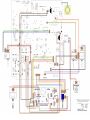
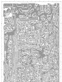
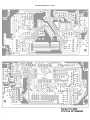
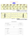
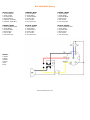
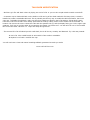
Ranger RCI 2950 Main PCB Schematic Diagram
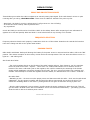
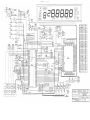
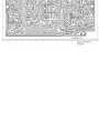
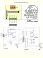
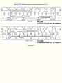
Ranger RCI 2950 CPU PCB Schematic Diagram
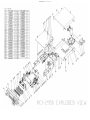
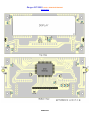
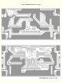
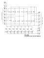
Ranger RCI 2950 Chassis Exploded View Drawing
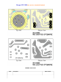
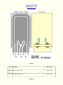
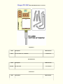
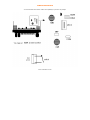
Ranger RCI 2950 LCD P.C. BOARD EPT2950217
Trace Layout
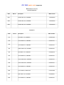
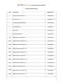
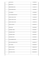
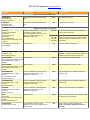
RESISTORS
Ref#
Description
MFR. Part No.
R710
39K .1 W CHIP
ROY013934Z
R711
470K .1W, CHIP
ROY014744Z
R712
680 K .1 W
ROY016844Z
CAPACITORS
Ref#
Description
MFR. Part No.
C701
1uF 16WV M, TANTALUM
CTY161056Z
C702
.33uF 35WV M, TANTALUM
CTY353346Z
C703
.33uF 35WV M, TANTALUM
CTY353346Z
C704
.33uF 35WV M, TANTALUM
CTY353346Z
C705
1uF 16WV M, TANTALUM
CTY161056Z
C707
.01uF, 50WV, Z, Z5V, MONO.
CK1103AB7U
C710
.1uF, 25WV, Z, Y5V, MONO.
CK2104AB7V
C711
.1uF, 25WV, Z, Y5V, MONO.
CK2104AB7V
C712
.1uF, 25WV, Z, Y5V, MONO.
CK2104AB7V
C713
.1uF, 25WV, Z, Y5V, MONO.
CK2104AB7V
C714
.1uF, 25WV, Z, Y5V, MONO.
CK2104AB7V
C715
.1uF, 25WV, Z, Y5V, MONO.
CK2104AB7V
C716
.1uF, 25WV, Z, Y5V, MONO.
CK2104AB7V
C717
.1uF, 25WV, Z, Y5V, MONO.
CK2104AB7V
C718
.1uF, 25WV, Z, Y5V, MONO.
CK2104AB7V
C719
.1uF, 25WV, Z, Y5V, MONO.
CK2104AB7V
C720
.1uF, 25WV, Z, Y5V, MONO.
CK2104AB7V
C721
.1uF, 25WV, Z, Y5V, MONO.
CK2104AB7V
Ref#
Description
MFR. Part No.
IC701
IC HD61602R
ENH161602R
Misc.
Ref#
Description
MFR. Part No.
-
RESISTOR, 1 M SEM I-FIXED
RE10500102
-
LCD DISPLAY
EX03N40438
-
LAMP, 5V .08A
EX01 N40080
-
IS SOCKET 2P
EX07N48442
-
PCB CONN. SOCK. 14P L= 21.8mm
EX07N48438
www.radioaficion.com
LCD P.C. BOARD EPT2950217 Trace Layout
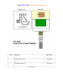
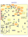
Ranger RCI 2950 CPU PCB EPT295043Z
Trace Layout
RESISTORS
Ref#
Description
MFR. Part No.
R601
270ohm 1/4W (U) TYPE, CARBON
RCU142714Z
R602
220ohm 1/4W (U) TYPE, CARBON
RCU142214Z
R603
180ohm 1/4W (U) TYPE, CARBON
RCU141814Z
R604
82ohm 1/4W (U) TYPE, CARBON
RCU148204Z
R605
470ohm .1 W CHIP
RCY014714Z
R606
470ohm .1W CHIP
RCY014714Z
R607
470ohm .1W CHIP
RCY014714Z
R608
470ohm .1 W CHIP
RCY014714Z
R609
10ohm .1 W, CHIP
RCY011034Z
R610
1ohm .1 W CHIP
RCY011024Z
R611
47K, 0.1W CHIP
RCY014734Z
R612
47K, 0AW CHIP
RCY014734Z
R613
47K, 0.1W CHIP
RCY014734Z
R614
47K, 0.1 W CHIP
RCY014734Z
R615
47K, 0.1W CHIP
RCY014734Z
R617
47K, 0.1W CHIP
RCY014734Z
R618
47K, 0.1 W CHIP
RCY014734Z
R619
47K,.0.1W CHIP
RCY014734Z
R620
470ohm .1W CHIP
RCY014714Z
R621
47K 0.1W CHIP
RCY014734Z
R622
47K 0.1 W CHIP
RCY014734Z
R623
47K 0.1W CHIP
RCY014734Z
R624
47K 0.1 W CHIP
RCY014734Z
R625
47K 0.1W CHIP
RCY014734Z
R626
4.7K 0.1 W CHIP
RCY014724Z
R627
47K 0.1W CHIP
RCY014734Z
R628
47K 0.1 W CHIP
RCY014734Z
R629
47K 0.1W. CHIP
RCY014734Z
R630
RESISTOR, 1MEG, 0.1 W, CHIP
RCY011054Z
R631
10ohm .1 W CHIP
RCY011034Z
R632
47K 0.1 W CHIP
RCY014734Z
R633
39K 0.1 W CHIP
RCY013934Z
R634
RESISTOR, 220K 0.1 W CHIP
RCY012244Z
R635
RESISTOR, 1MEG 0.1W CHIP
RCY011054Z
R636
RESISTOR, 100K 0.1W CHIP
RCY011044Z
R637
RESISTOR, 220K 0.1W CHIP
RCY012244Z
R638
RESISTOR, 100K 0.1W CHIP
RCY011044Z
R639
RESISTOR, 47K 0.1W CHIP
RCY014734Z
R640
RESISTOR, 47K 0.1W CHIP
RCY014734Z
R641
RESISTOR, 47K 0.1W CHIP
RCY014734Z
R642
RESISTOR, 47K 0.1W CHIP
RCY014734Z
R643
RESISTOR, 47K 0.1W CHIP
RCY014734Z
R644
RESISTOR, 47K 0.1W CHIP
RCY014734Z
R645
RESISTOR, 47K 0.1W CHIP
RCY014734Z
R646
RESISTOR, 47K O.1W CHIP
RCY014734Z
R647
RESISTOR, 47K O.1W CHIP
RCY014734Z
R648
RESISTOR, 47K 0.1W CHIP
RCY014734Z
R649
RESISTOR, 47K 0.1W CHIP
RCY014734Z
R650
RESISTOR, 47K 0.1W CHIP
RCY014734Z
R651
RESISTOR, 47K 0.1W CHIP
RCY014734Z
R652
RESISTOR, 47 K 0.1W CHIP
RCY014734Z
R653
RESISTOR, 47 K 0.1W CHIP
RCY014734Z
R654
RESISTOR, 47 K 0.1W CHIP
RCY014734Z
R655
RESISTOR, 47 K 0.1W CHIP
RCY014734Z
R656
RESISTOR, 47 K 0.1W CHIP
RCY014734Z
R657
RESISTOR, 47 K 0.1W CHIP
RCY014734Z
R658
RESISTOR, 47 K 0.1W CHIP
RCY014734Z
R659
RESISTOR, 47 K 0.1W CHIP
RCY014734Z
R660
RESISTOR, 47 K 0.1W CHIP
RCY014734Z
R661
RESISTOR, 47 K 0.1W CHIP
RCY014734Z
8662
RESISTOR, 47 K 0.1W CHIP
RCY014734Z
ARRAY RESISTORS
Ref#
Description
MFR. Part No.
RA601
RESISTOR ARRAY, 10K/20K 6P
RCS0670023
RA602
RESISTOR ARRAY, 47K 5P
RCS0570009
RA603
RESISTOR ARRAY, 47K 5P
RCS0570009
RA604
RESISTOR ARRAY, 220K 5P
RCS0570022
RA605
RESISTOR ARRAY, 47K 5P
RCS0570009
RA606
RESISTOR ARRAY, 220K 9P
RCS0970021
RA607
RESISTOR ARRAY, 47K 9P
RCS0970015
RA608
RESISTOR ARRAY, 47K 7P
RCS0770020
RA609
RESISTOR ARRAY, 47K 5P
RCS0570009
RA610
RESISTOR ARRAY, 220K 5P
RCS0570022
RA611
RESISTOR ARRAY, 47K 5P
RCS0570009
CAPACITORS
Ref#
Description
MFR. Part No.
C601
.01uF 50WV K Z5U, MONO.
CK1103AB7U
C602
.1uF 35WV M, TANTALUM
CTY351046Z
C603
.33uF 35WV M, TANTALUM
CTY353346Z
C604
.01uF 50WV KZ5U, MONO.
CK1103A87U
C605
.01uF 50WV KZ5U, MONO.
CK1103AB7U
C606
.01uF 50WV K Z5U, MONO.
CK1103AB7U
C607
.01uF 50WV K Z5 U, MONO.
CK1103AB7U
C608
.01uF 50WV KZ5U, MONO.
CK1103AB7U
C609
.01uF 50WV K Z5 U, MONO.
CK1103AB7U
C610
.01uF 50WV K Z5U, MONO.
CK1103A87U
C611
.01uF 50WV K Z5 U, MONl0.
CK1103A87U
C612
33PF 50WV J CH, MONO CHIP
CK1330AB4A
C613
33PF 50WV J CH, MONO CHIP
CK1330AB4A
C614
.1uF 50WV Z Y5V, MONO.
CK2104AB7V
C615
.0027uF 50WV Z Y5V, MONO.
CK1272AB5R
C616
470PF 50WV K SL, MONO. CHIP
CK1471AB5L
C617
100PF 50WV K SL, MONO CHIP
CK1101AB5L
C618
.01uF 50WV K Z5U, MONO.
CK1103AB7U
Integrated Circuits
Ref#
Description
MFR. Part No.
IC601
IC HD4074008F
ENH174008F
IC602
IC TC4069UBF
ENTA04069F
IC603
IC M5223FP
ENMI05223F
IC604
IC TC4069UBF
ENTA04069F
IC605
IC TA78
TZTA00078Z
IC606
IC TA78
TZTA00078Z
IC612
IC 7805
ENSS07805Z
TRANSISTORS
Ref#
Description
MFR. Part No.
TR601
TRANSISTOR 2SC945P
T2SC00945P
TR602
TRANSISTOR 2SC945P
T2SC00945P
TR603
TRANSISTOR 2SC945P
T2SC00945P
TR604
TRANSISTOR 2SC945P
T2SC00945P
TRANSISTOR 2SA1162GR
T2SA01162G
TR605
TRANSISTOR 2SC2712
T2SC02712G
TR606
TRANSISTOR 2SC2712
T2SC02712G
TR607
TRANSISTOR 2SC2712
T2SC02712G
-
DIODES
REF#
DESCRIPTION
PART#
D601
DIODE 1N5711
ED1N05711Z
D602
DIODE 1SS181
EDSS00181Z
D604
DIODE 1SS181
EDSS00181Z
D605
DIODE 1SS181
EDSS00181Z
Resonator
REF#
DESCRIPTION
PART#
X601
RESONATOR, 4MHZ, CERAMIC
EX14N46510
Switch
REF#
DESCRIPTION
S601
TACT SW
PART#
EWPS33042X
Buzzer
REF#
-
DESCRIPTION
PART#
BUZZER RKM35-4A
EX14N46511
Battery
REF#
L1
DESCRIPTION
PART#
BATTERY LITHIUM, 3V 170maH
EX08N41405
Connectors
REF#
DESCRIPTION
PART#
-
PCB CONNECTOR SOCKET 6P
EX07N41266
-
PCB CONNECTOR SOCKET 4P
EX07N41250
-
PCB CONNECTOR SOCKET 3P
EX07N41216
CN602
PCB CONNECTOR SOCKET 2P
EX07N41226
CN608
PCB CONNECTOR SOCKET 2P
EX07N41226
CN609
PCB CONNECTOR SOCKET 2P
EX07N41226
-
PCB CONNECTOR SOCKET 3P
EX07N48244
-
PCB CONNECTOR SOCKET 4P
EX07N48440
-
PCB CONNECTOR HOUSING 7P
EX07N48011
-
PCB CONNECTOR HOUSING 6P
EX07N48010
-
PCB CONNECTOR SOCKET 10P
EX07N48416
-
SHORT PIN 2P
EX07N48151
www.radioaficion.com
CPU PCB EPT295043Z Trace Layout
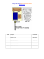
Ranger RCI-2950 MIC UP/DW PCB (EPT295080Z)
Ranger RCI 2950 MIC JACK P.C. BOARD EPT295070Z
CERAMIC CAPACITORS
Ref#
Description
MFR. Part No.
C701
.001uF 50WV Z SL, CERAMIC
CC0501027L
C702
.001uF 50WV Z SL, CERAMIC
CC0501027L
C703
.001uF 50WV Z SL, CERAMIC
CC0501027L
CONNECTORS
Ref#
Description
MFR. Part No.
J701
PCB CONNECTOR SOCKET 3P
EX07N48244
J702
PCB CONNECTOR SOCKET 2P
EX07N48152
J703
PCB CONNECTOR SOCKET 2P
EX07N48152
MIC JACK 6P
EX06N41111
www.radioaficion.com
Ranger RCI-2950
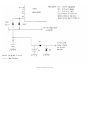
VSWR PCB (EPT360040Z)
Schematic Diagram
Resistors
Ref#
Description
MFR. Part No.
R401
100ohm 1/4W (P) TYPE
RCP141014Z
R402
150 OHM 1/4W (P) TYPE
RCP141514Z
Capacitors
Ref#
Description
MFR. Part No.
C405
.01uF 50WV Z SL, CERAMIC
CCO501037L
C406
.01uF 50WV Z SL, CERAMIC
CC0501037L
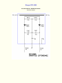
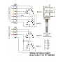
Ranger RCI-2950
RCI-2950 VSWR P.C. BOARD EPT360040Z
Schematic Diagram
Ranger RCI-2950 VR PCB RF/Mic Gain / Vol / SQ PCB (EPT295050Z)
Capacitors
Ref#
Description
MFR. Part No.
C501
.001uF 50WV Z SL, CERAMIC
CC0501027L
C505
.001uF 50WV Z SL, CERAMIC
CC0501027L
Potentiometers
Ref#
Description
MFR. Part No.
RF/MIC
VR 1KA-5KB
RV10203451
VOL/SQ
VR 5OKB-50KA
RV50303453
Connectors
Ref#
Description
MFR. Part No.
J501
PCB CONNECTOR SOCKET 2P
EX07N41226
J502
PCB CONNECTOR SOCKET 2P
EX07N41226
J503
PCB CONNECTOR SOCKET 3P
EX07N41216
J504
PCB CONNECTOR SOCKET 3P
EX07N41216
J505
PCB CONNECTOR SOCKET 2P
EX07N41226
Ranger RCI-2950 RCI-2950 VR (B) PCB (EPT295060Z)
Capacitors
Ref#
Description
MFR. Part No.
C601
.001 OF 50WV Z SL, CERAMIC
CCO501027L
Potentiometers
Ref#
RF/CAL
Description
MFR. Part No.
VR 1KB-20KB
RV10203456
Connectors
Ref#
Description
MFR. Part No.
J601
PCB CONN. SOCKET 3P
EX07N41216
J602
PCB CONN. SOCKET 3P
EX07N41216
Ranger RCI 2950 CH/SW P.C. BOARD EPT295090A
Ref#
Description
MFR. Part No.
ROTARY SW, GPS-688
EWRT32051S
PCB CONN. SOCKET, 3P
EX07N41216
www.radioaficion.com
Ranger RCI 2950 MODE P.C. BOARD EPT295090Z
Schematic Diagram
Ref#
J403
Description
MFR. Part No.
ROTARY SW, 6N
EWRT32053S
PCB CONN. SOCKET, 3P
EX07N41216
PCB CONN. SOCKET, 7P
EX07N41261
JUMPER WIRE 7x6x7mm
WX01070706
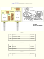
EPT295031Z Push Switch PCBEPT295031Z
Trace Layout
Schematic Diagram
CARBON FIXED RESISTORS
Ref#
Description
MFR. Part No.
1.5K 1/16W(P) TYPE
RCP161524Z
Misc.
Ref#
Description
MFR. Part No.
TACT SW
EWPS33042X
IC PIN
EX07N48414
LED YELLOW
EX01N40081
PCB CONN. SOCK. 6P L= 21.8mm
EX07N48441
Ranger RCI 2950 EPT295031Z Push Switch PCBEPT295031Z Trace Layout
www.radioaficion.com
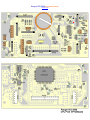
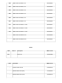
RCI 2950 PARTS LISTS Capacitors
Main PCB (EPT295013Z)
Trimmer Capacitors
Ref#
Bd Loc
Description
MFR. Part No.
VC1
CAPACITOR, 20P, TRIMMER
CV050200AZ
VC2
CAPACITOR, 20P, TRIMMER
CV050200AZ
VC3
CAPACITOR, 30P, TRIMMER
CV050300AZ
Capacitors
Ref#
Bd Loc
Description
MFR. Part No.
C1
5PF 50WV J CH, CERAMIC
CC0501004A
C2
.01uF 50WV Z SL, CERAMIC
CC0501037L
C3
.01uF 50WV Z SL, CERAMIC
CC0501037L
C4
100PF 50WV K SL, CERAMIC
CC0501015L
C5
5PF 50WV C CH, CERAMIC
CC0500501A
C6
.01uF 50WV Z SL, CERAMIC
CC0501037L
C7
.047uF 50WV Z SL, CERAMIC
CC0504737L
C8
.001uF 50WV Z SL, CERAMIC
CC0501027L
C9
.01uF 50WV Z SL, CERAMIC
CC0501037L
C10
4.7uF 16WV M, TANTALUM
CT0164756Z
C11
82PF 50WV J SL, CERAMIC
CC0508204L
C12
.01uF 50WV Z SL, CERAMIC
CC0501037L
C13
.47uF 50WV Z, ELECTROLYTIC
CE0504747Z
C14
330PF 50WV K SL, CERAMIC
CC0503315L
C15
.0022uF 50WV K, MYLAR
CM0502225Z
C16
2.2uF 5OWV Z, ELECTROLYTIC
CE0502257Z
C17
330PF 50WV K SL, CERAMIC
CC0503315L
C18
.01uF 50WV Z SL, CERAMIC
CC0501037L
C19
.047uF 50WV Z SL, CERAMIC
CC0504737L
C20
5PF 50WV C SL. CERAMIC
CC0500501L
C21
.01uF 50WV Z SL, CERAMIC
CC0501037L
C22
.1UF 50WV Z SL, CERAMIC
CCO501047L
C23
.1uF 50WV Z SL, CERAMIC
CC0501047L
C24
.01uF50WV Z SL, CERAMIC
CC0501037L
C25
10uF 25WV Z, ELECTROLYTIC
CE0251067Z
C27
10uF 25WV Z, ELECTROLYTIC
CE0251067Z
C28
.047uF50WV Z SL, CERAMIC
CC0504737L
C29
68PF 50WV J SL, CERAMIC
CC0506804L
C30
560PF 50WV K SL, CERAMIC
CC0505615L
C31
15PF 50WV J CH, CERAMIC
CC0501504A
C32
47uF 10WV Z, ELECTROLYTIC
CE0104767Z
C33
.001uF 50WV K, MYLAR
CM0501025Z
C34
.01uF 50WV Z SL, CERAMIC
CC0501037L
C35
100PF 50WV K SL, CERAMIC
CC0501015L
C36
10uF 25WV Z, ELECTROLYTIC
CE0251067Z
C37
270PF 50WV K SL, CERAMIC
CC0502715L
C38
.01uF50WV Z SL, CERAMIC
CC0501037L
C39
47uF 10WV Z, ELECTROLYTIC
CE0104767Z
C40
47uF 10WV Z, ELECTROLYTIC
CE0104767Z
C41
.001uF 50WV Z SL, CERAMIC
CC0501027L
C42
.1uF 50WV Z SL, CERAMIC
CC0501047L
C43
10PF 50WV J SL, CERAMIC
CC0501004L
C44
47uF 10WV Z, ELECTROLYTIC
CE0104767Z
C45
.001uF 50WV Z SL, CERAMIC
CC0501027L
C46
47uF 10WV Z, ELECTROLYTIC
CE0104767Z
C47
.022uF 50WV K, MYLAR
CM0502235Z
C48
.1uF 50WV Z SL, CERAMIC
CC0501047L
C49
47uF 10WV Z, ELECTROLYTIC
CE0104767Z
C50
10uF 25WV Z, ELECTROLYTIC
CE0251067Z
C51
.001uF 50WV Z SL, CERAMIC
CC0501027L
C52
220PF 5CWV K SL, CERAMIC
CC0502215L
C53
12PF 50WV J CH, CERAMIC
CC0501204A
C54
.047UF 50WV Z SL, CERAMIC
CC0504727L
C55
68PF 50WV J CH, CERAMIC
CC0506804A
C56
.01uF 50WV Z SL, CERAMIC
CC0501037L
C57
10uF 25WV Z, ELECTROLYTIC
CE0251067Z
C58
1000uF 10WV Z, ELECTROLYTIC
CE0101087Z
C59
.047uF 50WV Z SL, CERAMIC
CC0504737L
C60
.01uF 50WV Z SL, CERAMIC
CC0501037L
C61
5PF 50WV J CH, CERAMIC
CC0501004A
C63
.1uF 50WV Z SL, CERAMIC
CC0501047L
C65
56PF 50WV J CH, CERAMIC
CC0503304A
C66
1 PF 50WV C CH, CERAMIC
CC0500101A
C67
39PF 50WV J CH, CERAMIC
CC0503904A
C68
5PF 50WV C CH, CERAMIC
CC0500501A
C69
.01uF 50WV Z SL, CERAMIC
CC0501037L
C70
10uF 25WV Z, ELECTROLYTIC
CE0251067Z
C71
.01uF 50WV Z SL, CERAMIC
CC0501037L
C72
3PF 50WV C CH, CERAMIC
CC0500301A
C73
3PF 50WV C CH, CERAMIC
CC0500301A
C74
.01uF50EV Z SL, CERAMIC
CC0501037L
C75
27PF 50WV J SL, CERAMIC
CC0502704L
C76
.1uF 50WV Z SL, CERAMIC
CC0501047L
C77
5PF 50WV C SL, CERAMIC
CC0500501L
C78
.01 UF50WV Z SL, CERAMIC
CC0501037L
C79
.01 UF50WV Z SL, CERAMIC
CC0501037L
C80
.047uF 50WV Z SL, CERAMIC
CC0504737L
C81
2.2uF 50WV Z, ELECTROLYTIC
CE0502257Z
C82
47PF 50WV J SL, CERAMIC
CC0504704L
C83
.01uF 50WV Z SL, CERAMIC
CC0501037L
C84
.1uF 50WV Z SL, CERAMIC
CC0501047L
C85
.1uF 50WV Z SL, CERAMIC
CC0501047L
C86
.1uF 50WV Z SL, CERAMIC
CC0501047L
C87
220PF 50WV K SL, CERAMIC
CC0502215L
C88
1uF 50WV Z, ELECTROLYTIC
CE0501057Z
C89
5PF 50WV C SL, CERAMIC
CC0500501 L
C90
5PF 50WV C CH, CERAMIC
CC0500501A
C91
15PF 50WV J SL, CERAMIC
CC0501504L
C92
1uF 50WV Z SL, CERAMIC
CC0501047L
C93
1uF 50WV Z SL, CERAMIC
CC0501047L
C94
.01uF 50WV Z SL, CERAMIC
CC0501037L
C95
22uF 10WV Z, ELECTROLYTIC
CE01022677
C96
220uF 16WV Z, ELECTROLYTIC
CE0162277~
C97
.01uF 50WV Z SL, CERAMIC
CC0501037L
C98
100PF 50WV K SL, CERAMIC
CC0501015L
C99
220uF 16WV Z, ELECTROLYTIC
CE0162277Z
C100
.01uF50WV Z SL, CERAMIC
CC0501037L
C101
.001uF 50WV Z SL, CERAMIC
CC0501027L
C102
1uF 16WV NP, ELECTROLYTIC
CE0161056N
C103
220uF 10WV Z, ELECTROLYTIC
CE0102277Z
C104
.047uF 50WV Z SL, CERAMIC
CC0504737L
C105
5PF 50WV J CH, CERAMIC
CC0501004A
C106
.22uF 16WV M, TANTALUM
CT0162246Z
C107
.001uF 50WV Z SL, CERAMIC
CC0501027L
C108
12PF 50WV J SL, CERAMIC
CC0501204L
C109
4.7uF 50WV Z, ELECTROLYTIC
CE0504757Z
C110
.01uF 50WV Z SL, CERAMIC
CC0501037L
C111
100uF 10WV Z, ELECTROLYTIC
CE0101077Z
C112
47uF 10WV Z, ELECTROLYTIC
CE0104767Z
C113
.01uF 50WV Z SL, CERAMIC
CC0501037L
C114
270PF 50WV K SL, CERAMIC
CC0502715L
C115
220PF 50WV K SL, CERAMIC
CC0502215L
C116
220uF 16WV Z, ELECTROLYTIC
CE0162277Z
C117
.047uF 50WV Z SL, CERAMIC
CC0504737L
C118
.01uF 50WV Z SL, CERAMIC
CC0501037L
C119
5PF 50WV J CH, CERAMIC
CC0501004A
C120
.01uF 50WV Z SL, CERAMIC
CC0501037L
C121
33PF 50WV J SL, CERAMIC
CC0503304L
C122
33PF 50WV J SL, CERAMIC
CC0503304L
C123
.01uF 50WV Z SL, CERAMIC
CC0501037L
C124
.01uF 50WV Z SL, CERAMIC
CC0501037L
C125
.001uF 50WV Z SL, CERAMIC
CC0501027L
C126
.01uF 50WV Z SL, CERAMIC
CC0501037L
C127
.01uF 50WV Z SL, CERAMIC
CC0501037L
C128
47uF 10WV Z, ELECTROLYTIC
CE0104767Z
C129
.01uF 50WV Z SL, CERAMIC
CC0501037L
C130
10PF 50WV J SL, CERAMIC
CC0501004L
C131
.1uF 50WV Z SL, CERAMIC
CC0501047L
C132
.01uF 50WV Z SL, CERAMIC
CC0501037L
C133
47PF 50WV J UJ, CERAMIC
CC0504704G
C134
100PF 50WV K UJ, CERAMIC
CC0501015G
C135
.001uF 50WV Z SL, CERAMIC
CC0501027L
C136
.1uF 50WV Z SL, CERAMIC
CC0501047L
C137
10uF 25WV Z, ELECTROLYTIC
CE0251067Z
C138
1000uF 10WV Z, ELECTROLYTIC
CE0101087Z
C139
.001uF 50WV Z SL, CERAMIC
CC0501027L
C140
2.2uF 50WV Z, ELECTROYLTIC
CE0502257Z
C141
.22uF 16WV M, TANTALUM
CT0162246Z
C142
.001uF 50WV Z SL, CERAMIC
CC0501027L
C143
47uF 10WV Z, ELECTROLYTIC
CE0104767Z
C144
1uF 50WV Z, ELECTROLYTIC
CE0501057Z
C145
.001uF 50WV Z SL, CERAMIC
CC0501027L
C146
2.2uF 50WV Z, ELECTROLYTIC
CE0502257Z
C147
10uF 25WV Z, ELECTROLYTIC
CE0251067Z
C148
.1uF 50WV Z SL, CERAMIC
CC0501047L
C149
.001uF 50WV Z SL, CERAMIC
CC0501027L
C150
.47uF 50WV Z SL, CERAMIC
CC0504727L
C151
.47uF 50WV Z SL, CERAMIC
CC0504727L
C152
.01uF50WV Z SL, CERAMIC
CC0501037L
C153
.001uF 50WV Z SL, CERAMIC
CC0501027L
C154
100PF 50WV K SL, CERAMIC
CC0501015L
C155
.22uF 16WV M, TANTALUM
CT0162246Z
C156
4.7uF 16WV M, TANTALUM
CT0164756Z
C157
220uF 16WV Z, ELECTROLYTIC
CE0162277Z
C158
150PF 50WV K SL, CERAMIC
CC0501515L
C159
.001uF 50WV Z SL, CERAMIC
CC0501027L
C160
.22uF 16WV M, TANTALUM
CT0162246Z
C161
2.2uF 16WV M, TANTALUM
CT0162256Z
C162
.001uF 50WV Z SL, CERAMIC
CC0501027L
C163
47PF 50WV J SL, CERAMIC
CCO504704L
C164
560PF 50WV K SL, CERAMIC
CC0505615L
C165
390PF 50WV K SL, CERAMIC
CC0503915L
C166
33PF 50WV J SL, CERAMIC
CC0503304L
C167
150PF 50WV K SL, CERAMIC
CC0501515L
C168
10uF 25WV Z, ELECTROLYTIC
CE0251067Z
C169
33PF 50WV J SL, CERAMIC
CC0503304L
C170
10uF 25WV Z, ELECTROLYTIC
CE0251067Z
C171
10uF 16WV M, TANTALUM
CT0161066Z
C172
33PF 50WV J SL, CERAMIC
CC0503304L
C173
47PF 50WV J CH, CERAWMIC
CC0504704A
C174
100PF 50VVV K SL, CERAMIC
CC0501015L
C175
10uF 16WV M, TANTALUM
CT0161066Z
C176
33PF 50WV J SL, CERAMIC
CC0503304L
C177
.01uF 50WV Z SL, CERAMIC
CC0501037L
C178
10PF 50WV J SL, CERAMIC
CC0501004L
C179
33PF 50WV J SL, CERAMIC
CC0503304L
C180
33PF 50WV J SL, CERAMIC
CC0503304L
C181
100PF 50WV K SL, CERAMIC
CC0501015L
C182
100PF 50WV K SL, CERAMIC
CCO501015L
C183
100PF 50WV K UJ, CERAMIC
CC0501015G
C184
82PF 50WV J UJ, CERAMIC
CC0508204G
C186
.001uF 50WV K, MYLAR
CM0501025Z
C187
.001uF 50WV Z SL, CERAMIC
CC0501027L
C188
100PF 50VVV K SL, CERAMIC
CC0501015L
C189
33PF 50WV J SL, CERAMIC
CC0503304L
C190
22PF 50WV J SL, CERAMIC
CC0502204L
C191
.001uF 50WV Z SL, CERAMIC
CC0501027L
C192
10PF 50WV J SL, CERAMIC
CC0501004L
C193
100PF 50WV K SL, CERAMIC
CC0501015L
C194
100PF 50WV K SL, CERAMIC
CC0501015L
C195
33PF 50WV J SL, CERAMIC
CC0503304L
C196
47uF 10WV Z, ELECTROLYTIC
CE0104767Z
C197
.01uF 50WV Z SL, CERAMIC
CC0501037L
C198
33PF 50WVG J SL, CERAMIC
CC0503304L
C199
22PF 50WV J SL, CERAMIC
CC0502204L
C200
.001uF 50WV Z SL, CERAMIC
CC0501027L
C201
47uF 10WV Z, ELECTROLYTIC
CE0104767Z
C202
.1uF 50WV Z SL, CERAMIC
CC0501047L
C205
10uF 25WV Z, ELECTROLYTIC
CE0251067Z
C206
.01uF 50WV Z SL, CERAMIC
CC0501037L
C207
220uF 16WV Z, ELECTROLYTIC
CE0162277Z
C208
.01uF 50WV Z SL, CERAMIC
CC0501037L
C209
.01uF 50WV Z SL, CERAMIC
CC0501037L
C212
.001uF 50WV Z SL, CERAMIC
CC0501027L
C214
.1uF 50WV Z SL, CERAMIC
CC0501047L
C215
27PF 50WV J CH, CERAMIC
CC0502704A
C216
22uF 10WV Z, ELECTROLYTIC
CE0102267Z
C218
.1uF 50WV Z SL, CERAMIC
CC0501047L
C219
4.7uF 50WV Z, ELECTROLYTIC
CE0504757Z
C220
.01uF 50WV Z SL, CERAMIC
CC0501037L
C221
.047uF 50WV Z SL, CERAMIC
CC0504727L
C222
.1uF 50WV Z SL, CERAMIC
CC0501047L
C223
47uF 10WV Z, ELECTROLYTIC
CE0104767Z
C223
.1uF 50WVZ SL, CERAMIC
CC0501047L
C224
1uF 50WV Z, ELECTROLYTIC
CE0501057Z
C226
.047uF 50WV Z SL, CERAMIC
CC0504727L
C228
.01uF 50WV Z SL, CERAMIC
CC0501037L
C229
150PF 60WV K SL, CERAMIC
CC0501515L
C230
270PF 50WV K SL, CERAMIC
CC0502715L
C231
100uF 10WV Z, ELECTROLYTIC
CE0101077Z
C232
.01uF 50WV Z SL, CERAMIC
CCO501037L
C233
.001uF 50WV Z SL, CERAMIC
CC0501027L
C234
.047uF 50WV M K, MYLAR
CM0504735Z
C235
.001uF 50WV K, MYLAR
CM0501025Z
C236
.001uF 50WV Z SL, CERAMIC
CC0501027L
C237
5PF 50WV C CH, CERAMIC
CC0500501A
C238
150PF 50WV K RH, CERAMIC
CC0501515D
C239
56PF 50WV J RH, CERAMIC
CC0505604D
C240
.1uF 50WV Z SL, CERAMIC
CC0501047L
C242
.01uF 50EV Z SL, CERAMIC
CC0501037L
C243
100PF 50WV K UJ, CERAMIC
CC0501015G
C244
.047uF 50WV Z SL, CERAMIC
CC0504737L
C245
.1uF 50WV Z SL, CERAMIC
CC0501047L
C246
120PF 50WV K CH, CERAMIC
CC0501215A
C247
180PF 50WV K UJ, CERAMIC
CC0501815G
C248
3PF 50WV C CH, CERAMIC
CC0500301A
C249
5PF 50WV C CH, CERAMIC
CC0500501A
C250
.5PF 50WV C SL, CERAMIC
CC0500591L
C251
270PF 50WV K CH, CERAMIC
CC0502715A
C252
3PF 50WV C CH, CERAMIC
CC0500301A
C254
330PF 50WV K UJ, CERAMIC
CC0503315G
C255
150PF 50WV K UJ, CERAMIC
CC0501515G
C256
.1uF 50WV Z SL, CERAMIC
CC0501047L
C257
.1uF 50WV Z SL, CERAMIC
CC0501047L
C258
560PF 50WV K UJ, CERAMIC
CC0505615G
C259
.01uF 50EV Z SL, CERAMIC
CC0501037L
C260
.01uF 50EV Z SL, CERAMIC
CC0501037L
C261
560PF 50WV K UJ, CERAMIC
CC0505615G
C262
560PF 50WV K UJ, CERAMIC
CC0505615G
C263
10PF 50WV J SL, CERAMIC
CC0501004L
C264
.1uF 50WV Z SL, CERAMIC
CC0501047L
C265
2.2uF 50WV Z, ELECTROLYTIC
CE0502257Z
C266
.22uF 50WV, CHIP
CH0502246Z
C267
.1uF 50WV Z SL, CERAMIC
CC0501047L
C268
.01uF 50EV Z SL, CERAMIC
CC0501037L
C269
100PF 50WV K UJ, CERAMIC
CC0501015G
C270
560PF 50WV K UJ, CERAMIC
CC0505615G
C271
.1uF 50WV Z SL, CERAMIC
CC0501047L
C272
100PF 50WV K SL, CERAMIC
CC0501015L
C273
.001uF 50WV Z SL, CERAMIC
CC0501027L
C274
.01uF 50WV Z SL, CERAMIC
CC0501037L
C275
270PF 50WV K UJ, CERAMIC
CC0502715G
C276
.047uFm50WV Z SL, CERAMIC
CC0504727L
C277
5PF 50WV J CH, CERAMIC
CC0501004A
C278
33PF 50WV J CH, CERAMIC
CC0503304A
C279
180PF 50WV K UJ, CERAMIC
CC0501815G
C280
12PF 50WV J CH, CERAMIC
CC0501204A
C281
.1uF 50WV Z SL, CERAMIC
CC0501047L
C284
100PF 50WV J CH, CERAMIC
CCO501015A
C285
1uF 50WV Z, ELECTROLYTIC
CE0501057Z
C286
.01uF 50WV Z SL, CERAMIC
CC0501037L
C287
.01uF50WV Z SL, CERAMIC
CC0501037L
C288
10uF 25WV Z, ELECTROLYTIC
CE0251067Z
C289
.001uF 50WV Z SL, CERAMIC
CC0501027L
C290
560PF 50WV K UJ, CERAMIC
CC0505615G
C291
.01uF 50WV Z SL. CERAMIC
CC0501037L
C292
10uF 25WVZ, ELECTROLYTIC
CE0251067Z
C293
12PF 50WV J CH, CERAMIC
CC0501204A
C294
.47uF 50WV Z SL, CERAMIC
CC0504737L
C295
.1uF 50WV Z SL, CERAMIC
CC0501047L
C296
.01uF 50WV Z SL, CERAMIC
CC0501037L
C297
.01uF 50WV Z SL, CERAMIC
CC0501037L
C298
.1uF 50WV Z SL, CERAMIC
CC0501047L
C299
.1uF 50WV Z SL, CERAMIC
CC0501047L
C300
.047uF 50WV Z SL, CERAMIC
CC0504737L
C301
100uF 10WV Z, ELECTROLYTIC
CE0101077Z
C302
.001uF 50WV Z SL, CERAMIC
CC0501027L
C303
.047uF 50WV Z SL, CERAMIC
CC0504737L
C304
2200uF 16WV Z, ELECTROLYTIC
CE0162287Z
C305
.01uF 50WV Z SL, CERAMIC
CC0501037L
C306
.001uF 50WV Z SL, CERAMIC
CC0501027L
C307
.01uF 50WV Z SL, CERAMIC
CC0501037L
C308
.01uF 50WV Z SL, CERAMIC
CC0501037L
C309
.001uF 50WV Z SL, CERAMIC
CC0501027L
C310
.1uF 50WV Z SL, CERAMIC
CC0501047L
C311
.01uF 50WV Z SL. CERAMIC
CC0501037L
C312
.047uF 50WV Z SL, CERAMIC
CC0504737L
C313
.1uF 50WV Z SL, CERAMIC
CC0501047L
C314
.1uF 50WV Z SL, CERAMIC
CC0501047L
C316
.001uF 50WV Z SL, CERAMIC
CC0501027L
C317
.047uF 50WV Z SL. CERAMIC
CC0504737L
C319
10PF 50WV J SL, CERAMIC
CC0501004L
C320
.01uF 50WV Z SL, CERAMIC
CC0501037L
C321
.01uF 50WV Z SL, CERAMIC
CC0501037L
C322
2200uF 16WV Z, ELECTROLYTIC
CE0162287Z
C323
.001 PF 50WV Z SL, CERAMIC
CC0501027L
C324
.1UF 50WV Z SL. CERAMIC
CC0501047L
C325
.01uF 50WV Z SL. CERAMIC
CC0501037L
C326
.1UF 50WV Z SL, CERAMIC
CC0501047L
C327
.01uF 50WV Z SL. CERAMIC
CC0501037L
C328
.22uF 50WV, CHIP
CH0502246Z
C329
.01uF 50WV Z SL, CERAMIC
CC0501037L
C330
.001uF 50WV Z SL, CERAMIC
CC0501027L
C331
.1UF 50WV Z SL, CERAMIC
CC0501047L
C332
.1uF 50WV Z SL, CERAMIC
CC0501047L
C333
.1uF 50WV Z SL, CERAMIC
CC0501047L
C334
.1uF 50WV Z SL, CERAMIC
CC0501047L
C335
.1uF 50WV Z SL, CERAMIC
CC0501047L
C336
.1uF 50WV Z SL, CERAMIC
CC0501047L
C337
.1uF 50WV Z SL, CERAMIC
CC0501047L
C338
.01uF 50WV Z SL, CERAMIC
CC0501037L
C339
100PF 50WV KSL, CERAMIC
CC0501015L
C340
.01uF 50WV Z SL, CERAMAIC
CC0501037L
C341
100PF 50WV K SL, CERAMIC
CC0501015L
C343
.001uF 50WV Z SL, CERAMIC
CC0501027L
C345
.22uF 50WV, CHIP
CH0502246Z
C347
1uF 50WV Z, ELECTROLYTIC
CE0501057Z
C348
3PF 50WV C CH, CERAMIC
CC050030 IA
C349
.01uF 50WV Z SL, CERAMIC
CC0501037L
www.radioaficion.com
RCI 2950 PARTS LISTS Coils, Transformers, Crystals, Filters
Main PCB (EPT295013Z)
Filters
Ref#
Bd Loc
Description
MFR. Part No.
FL1
FILTER, CFW455HT, CERAMIC
EFCFW455HT
FL2
FILTER, SEF 10.7 MX, CERAMIC
EFCFE107MX
FL3
FILTER, 10.695 MHZ, CRYSTAL
EFX8106952
Crystals
Ref#
Bd Loc
Description
MFR. Part No.
X1
10.240 MHZ, CRYSTAL
EYCAB10240
X2
10.240 MHZ, CRYSTAL
EYCAB10240
X3
10.6975 MHZ, CRYSTAL
EYCAE10697
Inductors
Ref#
Bd Loc
Description
MFR. Part No.
L1
IFT M199CC-P14097F
ECIFT12251
L2
IFT 199CC-PI498N
ECIFT12252
L3
IFT 7MC-7172ABN
ECIFT12002
L4
IFT M199CC-P14097F
ECIFT12251
L5
IFT 7MC-7172ABN
ECIFT12002
L6
IFT 7MC-7172ABN
ECIFT12002
L7
IFT 7MC-7174Y
ECIFT12003
L8
M199CNFP1499N
ECIFT12253
L9
IFT 199CN-P1549N
ECIFT12290
L11
IFT 199CN-P1549N
ECIFT12290
L12
IFT M199CC-P1501A
ECIFT12255
L13
IFT 199CC-Pl 502N
ECIFT12256
L14
IFT 199CC-P1502N
ECIFT12256
L15
IFT 199CC-P1498N
ECIFT12252
L16
IFT M199CC-P1503A
ECIFT12257
L17
IFT 292CN-Pl 121Z
ECIFT12263
L18
COIL, BEAD F PH= 12.5MM
ECBAD18550
L19
COIL, BEAD F PH= 12.5MM
ECBAD18550
L19
IFT M199CC-PI504N
ECIFT12258
L21
IFT 292CN-Pl 121Z
ECIFF12263
L22
COIL, CHOKE 22 UH (P TYPE)
L23
IFT 199CC-P1498N
ECIFT12252
L24
IFT 199CC-P1498N
ECIFT12252
L25
IFT 199CC-PI498N
ECIFT12252
L26
COIL, CHOKE 470 UH (P TYPE)
L27
IFT 113CN-63442
ECIFT12016
L28
IFT 113CN-63442
ECIFT12016
ECCHK16070
ECCHK16096
L29
IFT 113CN-63442
L30
COIL, CHOKE 22 UH (P TYPE)
ECCHK16070
L33
COIL, CHOKE .82 UH
ECCHK16082
L34
COIL, RF .23UH
ECRFZ10001
L36
COIL, BEAD D SU-B-172D
ECBAD18504
L37
COIL, BEAD D SU-B-172D
ECBAD18504
L38
COIL, RF .23UH
ECRFZ10091
L39
COIL, BEAD F SU-B-172E
ECBAD18506
L40
COIL, BEAD D SU-B-172D
ECBAD18504
L41
COIL, TOROIDAL SUTR-398
ECRFZ10048
L42
COIL, BEAD F SU-B-172E
ECBAD18506
L43
IFT 292CN-Pl 117AQ
ECIFT12262
L44
COIL, BEAD F PH= 12.5MM
ECBAD18550
L45
COIL, BEAD F PH= 12.5MM
ECBAD18550
L46
IFT 292CN-PI 125R
ECIFT12265
L47
IFT 292CN-Pl 125R
ECIFT12265
L48
IFT M199CC-P1501A
ECIFT12255
L49
COIL. CHOKE (BIG ROUND)
ECCHK16151
L50
COIL, CHOKE .82 UH
ECCHK16082
L51
COIL, CHOKE 10 CHIP) TYPE
ECCHK16088
L52
COIL, CHOKE 10 CHIP) TYPE
ECCHK16088
ECIFT12016
L53
COIL, CHOKE 470 UH (P TYPE)
ECCHK16096
L59
COIL, BEAD F SU-B-172E
ECBAD18506
L60
COIL, BEAD F SU-B-172E
ECBAD18506
L61
COIL, BEAD F SU-B-172E
ECBAD18506
L62
COIL, BEAD E PH= 10MM
ECBAD18526
L63
COIL, CHOKE 470 UH (P TYPE)
ECCHK16096
L65
COIL, BEAD F SU-B-172E
ECBAD18506
L131
COIL, SPRING .8x6x8.5t
ECSPG18075
L132
COIL, SPRING .8x6.5x7.5t
ECSPR18003
L503
COIL, CHOKE.47 UH (P TYPE)
ECCHK16000
L504
COIL, CHOKE.47 UH (P TYPE)
ECCHK16000
J52
COIL, CHOKE 470 UH (P TYPE)
ECCHK16096
T1
COIL, CHOKE EI-19 TF-083
ECCHK16004
www.radioaficion.com
RCI 2950 PARTS LISTS Resistors
Main PCB (EPT295013Z)
Variable Resistors
Ref#
Bd Loc
Description
MFR. Part No.
VR1
10K 3P, SEMI FIXED
RE10300078
VR2
10K 3P, SEMI FIXED
RE10300078
VR3
500K 3P, SEMI FIXED
RE50400080
VR4
500K 3P, SEMI FIXED
RE50400080
VR7
10K 3P, SEMI FIXED
RE10300078
VR8
100K 3P, SEMI FIXED
RE10400079
VR11
3K 3P, SEMI FIXED
RE30200076
VR12
10K 3P, SEMI FIXED
RE10300078
VR13
5K 3P, SEMI FIXED
RE50200077
VR14
1K 3P, SEMI FIXED
RE10200072
VR15
1K 3P, SEMI FIXED
RE10200072
VR16
10K 3P, SEMI FIXED
RE10300078
VR21
5K 3P, SEMI FIXED
RE50200077
Resistors
Ref#
Bd Loc
Description
MFR. Part No.
R1
10K 1/4W (U) TYPE
RCU141034Z
R2
33K 1/4W (U) TYPE
RCU143334Z
R3
680ohm 1/4W (U) TYPE
RCU146814Z
R4
220ohm 1/4W (U) TYPE
RCU142214Z
R5
330ohm 1/4W (U) TYPE
RCU143314Z
R6
47K 1/4W (U) TYPE
RCU144734Z
R7
2.2 K 1/4W (U) TYPE
RCU142224Z
R8
330ohm 1/4W (U) TYPE
RCU143314Z
R9
56ohm 1/4W (U) TYPE
RCU145604Z
R10
100K 1/4W (U) TYPE
RCU141044Z
R11
10K 1/4W (U) TYPE
RCU141034Z
R12
6.8 K 1/4W (U) TYPE
RCU146824Z
R13
470K 1/4W (U) TYPE
RCU144744Z
R14
10K 1/4W (U) TYPE
RCU141034Z
R15
330ohm 1/4W (U) TYPE
RCU143314Z
R16
2.7 K 1/4W (U) TYPE
RCU142724Z
R17
1.8 K 1/4W (U) TYPE
RCU141824Z
R18
1 K 1/4W (U) TYPE
RCM141024A
R19
6.8 K 1/4W (U) TYPE
RCU146824Z
R20
100ohm 1/4W (U) TYPE
RCM141014A
R21
1 K 1/4W (U) TYPE
RCU141024Z
R22
1.5K 1/4W (U) TYPE
RCU141524Z
R23
2.7K 1/4W (U TYPE
RCM142724A
R24
1.5K 1/4W (U) TYPE
RCU141524Z
R25
10K 1/4W (U) TYPE
RCM141034A
R27
1.8 K 1/4W (U) TYPE
RCU141824Z
R28
1.8 K 1/4W (U) TYPE
RCU141824Z
R29
47K 1/4W (U) TYPE
RCM144734A
R30
100ohm 1/4W (U) TYPE
RCM141014A
R31
100ohm 1/4W (U) TYPE
RCU141014Z
R32
100ohm 1/4W (U) TYPE
RCU141014Z
R33
100ohm 1/4W (U) TYPE
RCM141014A
R34
4.7K 1/4W (U) TYPE
RCM144724A
R35
6.8K 1/4W (U) TYPE
RCU146824Z
R36
6.8K 1/4W (U) TYPE
RCM146824A
R37
100ohm 1/4W (U) TYPE
RCU141014Z
R38
1K 1/4W (U) TYPE
RCU141024Z
R39
330K 1/4W (U) TYPE
RCU143344Z
R40
1 M 1/4W (U) TYPE
RCU141054Z
R41
6.8K 1/4W (U) TYPE
RCM146824A
R42
100K 1/4W (U) TYPE
RCU141044Z
R43
100K 1/4W (U) TYPE
RCU141044Z
R44
100K 1/4W (U) TYPE
RCU141044Z
R45
82K 1/4W (U) TYPE
RCU148234Z
R46
47K 1/4W (U) TYPE
RCM 144734A
R47
220K 1/4W (U) TYPE
RCU142244Z
R48
680K 1/4W (U) TYPE
RCU146844Z
R49
100K 1/4W (U) TYPE
RCM 141044A
R50
100 K1/4W (U) TYPE
RCM141044B
R51
220K 1/4W (U) TYPE
RCM142244A
R52
1 K, 1/4W (U) TYPE
RCU141024Z
R53
1 K, 1/4W (U) TYPE
RCU141024Z
R54
100K 1/4W (U) TYPE
RCM141044A
R55
100K 1/4W (U) TYPE
RCM141044A
R56
3.3K 1/4W (U) TYPE
RCM143324A
R57
3.3K 1/4W (U) TYPE
RCU143324Z
R58
3.3K 1/4W (U) TY PE
RCU143324Z
R59
47K 1/4W (U) TYPE
RCU144734Z
R60
3.3K 1/4W (U) TYPE
RCU143324Z
R61
3.3K 1/4W (U) TYPE
RCU143324Z
R62
10K 1/4W (U) TYPE
RCU141034Z
R63
47K 1/4W (U) TYPE
RCU144734Z
R64
2.7K 1/4W (U) TYPE
RCU142724Z
R65
1 K, 1/4W (U) TYPE
RCU141024Z
R66
10K 1/4W (U) TYPE
RCU141034Z
R67
1K, 1/4W (U) TYPE
RCU474157Z
R68
1K 1/4W (U) TYPE
RCM141024A
R69
1K, 1/4W (U) TYPE
RCU141024Z
R70
10K 1/4W (U) TYPE
RCM141034A
R71
47K 1/4W (U) TYPE
RCU144734Z
R72
6.8K 1/4W (U) TYPE
RCM146824A
R73
1K, 1/4W (U) TYPE
RCU141024Z
R74
100K 1/4W (P) TYPE
RCP141044Z
R75
680ohm 1/4W (U) TYPE
RCU146814Z
R76
1.5K 1/4W (U) TYPE
RCU141524Z
R77
10K 1/4W (U) TYPE
RCU141034Z
R78
2.8K 1/4W (U) TYPE
RCU142224Z
R79
2.7K 1/4W(UO TYPE
RCU142724Z
R80
100ohm 1/4W (U) TYPE
RCU141014Z
R81
2.2K 1/4W (U) TYPE
RCM142224A
R82
100K 1/4W (U) TYPE
RCU141044Z
R84
100ohm 1/4W (U) TYPE
RCU141014Z
R85
1.8K 1/4W (U) TYPE
RCU141824Z
R86
1 K 1/4W (U) TYPE
RCU141024Z
R87
5.6K 1/4W (U) TYPE
RCM145624A
R88
10K 1/4W (U) TYPE
RCU141034Z
R89
10K 1/4W (U) TYPE
RCM141034A
R90
1K 1/4W (U) TYPE
RCU141024Z
R91
10K 1/4W (U) TYPE
RCU141034Z
R92
1.5K 1/4W (U) TYPE
RCU141524Z
R93
680ohm 1/4W (U) TYPE
RCM146814B
R94
1.2K, 1/4W (U) TYPE
RCU141224Z
R95
8.2K 1/4W (U) TYPE
RCU148224Z
R96
22K 1/4W (U) TYPE
RCM142234B
R97
1.8K 1/4W (U) TYPE
RCU141824Z
R98
5.6K 1/4W (U) TYPE
RCU145624Z
R99
1K 1/4W (U) TYPE
RCU141024Z
R100
47K 1/4W (U) TYPE
RCM144734A
R101
1.5K 1/4W (U) TYPE
RCU141524Z
R102
220ohm 1/4W (U) TYPE
RCU142214Z
R103
100ohm 1/4W (U) TYPE
RCU141014Z
R104
100ohm 1/4W (U) TYPE
RCM141014A
R105
1M 1/4W (U) TYPE
RCU141054Z
R106
6.8K 1/4W (U) TYPE
RCU146824Z
R107
100K 1/4W (U) TYPE
RCU141044Z
R108
68K 1/4W (U) TYPE
RCU146834Z
R709
100K 1/4W (U) TYPE
RCU141044Z
R110
1.5M 1/4W (U) TYPE
RCU141554Z
R111
68K 1/4W (U) TYPE
RCU146834Z
R712
22K 1/4W (U) TYPE
RCM142234A
R113
2.7K 1/4W (U) TYPE
RCU142724Z
R114
680K 1/4W (U) TYPE
RCM146844A
R115
220K 1/4W (U) TYPE
RCU142244Z
R116
47K 1/4W (U) TYPE
RCU144734Z
R117
1K 1/4W (U) TYPE
RCU141024Z
R118
10K 1/4W (U) TYPE
RCM141034A
R119
10ohm 1/4W (U) TYPE
RCU141004Z
R120
1K 1/4W (U) TYPE
RCU141024Z
R121
27K 1/4W (U) TYPE
RCU142734Z
R722
1K 1/4W (U) TYPE
RCU141024Z
R123
10K 1/4W (U) TYPE
RCU141034Z
R124
10K 1/4W (U) TYPE
RCU141034Z
R725
100K 1/4W (U) TYPE
RCU141044Z
R126
10K 1/4W (U) TYPE
RCU141034Z
R127
1K 1/4W (U) TYPE
RCU141024Z
R128
220ohm 1/4W (U) TYPE
RCU142214Z
R129
10K 1/4W (U) TYPE
RCU141034Z
R730
10K 1/4W (U) TYPE
RCU141034Z
R131
10K 1/4W (U) TYPE
RCU141034Z
R132
100ohm 1/4W (U) TYPE
RCU141014Z
R133
10K 1/4W (U) TYPE
RCU141034Z
R134
10K 1/4W (U) TYPE
RCU141034Z
R135
220C21/4W (U) TYPE
RCU142214Z
R136
56ohm 1/4W (U) TYPE
RCU145604Z
R137
560ohm 1/4W (U) TYPE
RCU145614Z
R138
150ohm 1/4W (U) TYPE
RCU141514Z
R139
220K 1/4W (U) TYPE
RCU142244Z
R140
1.5K 1/4W (U) TYPE
RCM141524A
R141
100ohm 1/4W (U) TYPE
RCU141014Z
R142
1K 1/4W (U)TYPE
RCU141024Z
R143
10K 1/4W (U) TYPE
RCU141034Z
R144
330ohm 1/4W (U) TYPE
RCU143314Z
R145
10K 1/4W (U) TYPE
RCU141034Z
R146
10K 1/4W (U) TYPE
RCU141034Z
R147
1K 1/4W (U) TYPE
RCM141024A
R148
270K 1/4W (U)TYPE
RCM142744A
R150
270K 1/4W (U) TYPE
RCU142274Z
R151
3.3K 1/4W (U) TYPE
RCU143324Z
R152
4.7K 1/4W (U) TYPE
RCM144724A
R153
10K 1/4W (U) TYPE
RCU141034Z
R154
3.3K 1/4W (U) TYPE
RCU143324Z
R155
220ohm 1/4W (U) TYPE
RCM142214A
R156
100ohm 1/4W (U) TYPE
RCU141014Z
R757
1K 1/4W (P) TYPE
RCP141024Z
R159
10K 1/4W (U) TYPE
RCU141034Z
R160
330K 1/4W (U) TYPE
RCU143344Z
R161
220ohm 1/4W (U) TYPE
RCU142214Z
R162
100K 1/4W (U) TYPE
RCU141044Z
R163
470K 1/4W (U) TYPE
RCU144744Z
R164
15K 1/4W (U) TYPE
RCU141534Z
R166
10K 1/4W (U) TYPE
RCU141034Z
R167
100K 1/4W (U) TYPE
RCU141044Z
R168
47K 1/4W (U) TYPE
RCU144734Z
R169
10K 1/4W (U) TYPE
RCU141034Z
R170
10K 1/4W (U) TYPE
RCU141034Z
R171
1K, 1/4W (U) TYPE
RCU141024Z
R172
1K, 1/4W (U) TYPE
RCU141024Z
R173
47ohm 1/4W (U) TYPE
RCU144714Z
R174
3.3K 1/4W (U) TYPE
RCM143324A
R175
1.5K, 1/4W (U) TYPE
RCU141524Z
R176
2.7K 1/4W (U) TYPE
RCU142724Z
R177
10K 1/4W (U) TYPE
RCU141034Z
R178
3.3K 1/4W (U) TYPE
RCU143324Z
R179
1.5M 1/4W (U) TYPE
RCU141554Z
R180
10K 1/4W (P) TYPE
RCP252034Z
R181
10K 1/4W (U) TYPE
RCU141034Z
R182
3.3K 1/4W (U) TYPE
RCU143324Z
R183
3.3K 1/4W (U) TYPE
RCU143324Z
R184
1.8K 1/4W (U) TYPE
RCU141824Z
R185
100ohm 1/4W (U) TYPE
RCU141014Z
R186
3.3K 1/4W (U) TYPE
RCM143324A
R788
47K 1/4W (U) TYPE
RCU144734Z
R189
10K 1/4W (U) TYPE
RCM141034B
R190
10K 1/4W (U) TYPE
RCU141034Z
R191
220K 1/4W (U) TYPE
RCU142244Z
R192
100K 1/4W (U) TYPE
RCM141044A
R193
10K 1/4W (U) TYPE
RCU141034Z
R194
10K 1/4W (U) TYPE
RCU141034Z
R195
47K 1/4W (U) TYPE
RCM144734A
R196
680ohm 1/4W (U) TYPE
RCM146814A
R197
100ohm 1/4W (U) TYPE
RCU141014Z
R198
1.8K 1/4W (U) TYPE
RCU141824Z
R199
47K 1/4W (U) TYPE
RCU144734Z
R200
22K 1/4W (U) TYPE
RCU142234Z
R201
10K 1/4W (U) TYPE
RCU141034Z
R202
56ohm 1/4W (U)TYPE
RCM145604A
R203
10K 1/4W (U) TYPE
RCU141034Z
R204
560ohm 1/4W (U) TYPE
RCU145614Z
R205
2.7K 1/4W (U) TYPE
RCU142724Z
R206
100ohm 1/4W (U) TYPE
RCU141014Z
R207
22ohm 1/4W (U) TYPE
RCM142204A
R208
100ohm 1/4W (U) TYPE
RCU141014Z
R209
22ohm 1/4W (U) TYPE
RCU142204Z
R210
1K 1/4W (U )TYPE
RCU141024Z
R211
4.7K 1/4W (U) TYPE
RCU144724Z
R212
33K 1/4W (U) TYPE
RCU143334Z
R213
10K 1/4W (U) TYPE
RCM141034A
R214
10K 1/4W (U) TYPE
RCU141034Z
R215
3.3K 1/4W (U) TYPE
RCU143324Z
R216
10K 1/4W (U) TYPE
RCU141034Z
R217
10K 1/4W (U) TYPE
RCM141034A
R218
1 K 1/4W (U) TYPE
RCM141024A
R219
22K 1/4W (U) TYPE
RCU142234Z
R220
1K 1/4W (U) TYPE
RCU141024Z
R221
10K 1/4W (U) TYPE
RCU141034Z
R222
4.7K 1/4W (U) TYPE
RCM144724B
R223
6.8K 1/4W (U) TYPE
RCM146824A
R224
56ohm 1/4W (U) TYPE
RCU145604Z
R225
1K 1/4W (U) TYPE
RCM141024A
R226
10K 1/4W (U) TYPE
RCM141034A
R227
22K 1/4W (U) TYPE
RCU142234Z
R228
3.3K 1/4W (U) TYPE
RCU143324Z
R229
220K 1/4W (U) TYPE
RCU142244Z
R230
1K 1/4W (U) TYPE
RCU141024Z
R231
470K 1/4W (U) TYPE
RCU144744Z
R232
4.7K 1/4W (P) TYPE
RCP144724Z
R233
100ohm 1/4W (U) TYPE
RCU141014Z
R234
10K 1/4W (P) TYPE
RCP141034Z
R235
10K 1/4W (U) TYPE
RCU141034Z
R236
330ohm 1/4W (U) TYPE
RCU143314Z
R237
10K 1/4W (U) TYPE
RCU141034Z
R238
10K 1/4W (U) TYPE
RCU141034Z
R239
220ohm 1/4W (U) TYPE
RCU145614Z
R240
10K 1/4W (U) TYPE
RCM141034A
R241
1.8K 1/4W (U) TYPE
RCU141824Z
R242
100ohm 1/4W (U) TYPE
RCM141014A
R243
47K 1/4W (U) TYPE
RCU144734Z
R244
22K 1/4W (U) TYPE
RCU142234Z
R245
47K 1/4W (U) TYPE
RCU144734Z
R247
4.7K 1/4W (U) TYPE
RCU144724Z
R248
1K 1/4W (U) TYPE
RCU141024Z
R250
1K 1/4W (U)TYPE
RCM141024A
R251
10K 1/4W (P) TYPE
RCP121034Z
R252
1K 1/4W (U) TYPE
RCM141024A
R253
18ohm 1/4W (U) TYPE
RCU141804Z
R254
1ohm 1/4W (P) TYPE
RCP141094Z
R255
150ohm 1/2W (P)
RCP121514Z
R256
18ohm 1/4W (U) TYPE
RCU141804Z
R257
150ohm 1/2W (P) TYPE
RCP121514Z
R258
2.2ohm 1/4W (P) TYPE
RCP142294Z
R259
150ohm 1/4W (U) TYPE
RCU141514Z
R260
4.7ohm 1/4W (U) TYPE
RCU144794Z
R261
1.5K 1/4W (U) TYPE
RCU141524Z
R262
330ohm 1/4W (U) TYPE
RCU143314Z
R264
47ohm 1/4W (U) TYPE
RCU144704Z
R265
330ohm 1/4W (U) TYPE
RCU143314Z
R266
1.5K 1/4W (U) TYPE
RCU141524Z
R268
1 K 1/4W (U) TYPE
RCU141024Z
R269
100K 1/4W (U) TYPE
RCU141044Z
R270
100K 1/4W (U) TYPE
RCU141044Z
R272
100K 1/4W (U) TYPE
RCU141044Z
R273
100ohm 1/4W (U) TYPE
RCU141014Z
R274
10K 1/4W (U) TYPE
RCU141034Z
R276
150ohm 1/4W (U) TYPE
RCU141514Z
R277
1.8K 1/4W (U) TYPE
RCU141824Z
R278
10K 1/4W (U) TYPE
RCU141034Z
R279
100ohm 1/4W (U) TYPE
RCM141014A
R280
4.7K 1/4W (U) TYPE
RCM144724A
R281
4.7K 1/4W (U) TYPE
RCU144724Z
R282
4.7K 1/4W (P) TYPE
RCP144724Z
R283
10K 1/4W (U) TYPE
RCM141034A
R284
1K, 1/4W (U) TYPE
RCU141024Z
R285
470ohm 1/4W (U) TYPE
RCU144714Z
R286
15ohm 1/4W (U) TYPE
RCU141504Z
R287
2.7K 1/4W (U) TYPE
RCU142724Z
R289
470ohm 1/4W (U) TYPE
RCU144714Z
R290
10K 1/4W (U) TYPE
RCU141034Z
R291
10K 1/4W (U) TYPE
RCU141034Z
R292
4.7K 1/4W (U) TYPE
RCM144724B
R293
10K 1/4W (U) TYPE
RCU141034Z
R294
4.7K 1/4W (U) TYPE
RCU144724Z
R295
10K 1/4W (U) TYPE
RCU141034Z
R296
10K 1/4W (U) TYPE
RCU141034Z
R297
10ohm 1/4W (U) TYPE
RCU141004Z
R298
1K 1/4W (U) TYPE
RCU141024Z
R299
10K 1/4W(U) TYPE
RCU141034Z
R300
560ohm 1/4W (U) TYPE
RCU145614Z
R301
6.8K 1/4W (U) TYPE
RCU146824Z
R302
1K 1/4W (P) TYPE
RCP141024Z
R303
10K 1/4W (U) TYPE
RCU141034Z
R304
1ohm 1/4W (P) TYPE
RCP141094Z
R305
220ohm 1/4W (U) TYPE
RCM142214
R306
10K 1/4W (U) TYPE
RCU141034Z
R307
1K 1/4W (U) TYPE
RCU141024Z
R308
100ohm 1/4W (U) TYPE
RCU141014Z
R309
27K 1/4W (U) TYPE
RCU142734Z
R310
270K 1/4W (U) TYPE
RCU142274Z
R311
1 K 1/4W (U) TYPE
RCM141024
R312
1 K, 1/4W (U) TYPE
RCU141024Z
R313
1 K, 1/4W (U) TYPE
RCU141024Z
R314
10K 1/4W (U) TYPE
RCU141034Z
R315
22K 1/4W (U) TYPE
RCU142234Z
R317
1K, 1/4W (U)TYPE
RCU141024Z
R318
100ohm 1/4W (U) TYPE
RCM141014
R319
1K, 1/4W (U)TYPE
RCU141024
R321
10K 1/4W (U) TYPE
RCU141034
R322
100K 1/4W (U) TYPE
RCM141044A
R323
33K 1/4W (U) TYPE
RCU143334Z
R324
4.7K 1/4W (U) TYPE
RCM144724A
R325
10K 1/4W (U) TYPE
RCU141034Z
R326
1K 1/4W (U) TYPE
RCM141024A
R327
10K 1/4W (U) TYPE
RCU141034Z
R330
1K 1/4W (U) TYPE
RCU141024Z
R331
10K 1/4W (U) TYPE
RCM141034A
R332
1K 1/4W (U) TYPE
RCU141024Z
R334
100ohm 1/4W (U) TYPE
RCM141014B
R335
10K 1/4W (U) TYPE
RCU141034Z
R336
10K 1/4W (U) TYPE
www.radioaficion.com
RCM141034A
RCI 2950 PARTS LISTS IC's, Transistors
Main PCB (EPT295013Z)
Integrated Circuits
Ref#
Bd Loc
Description
MFR. Part No.
IC1
I.C. NJM324D
ENJR00324D
IC2
I.C. UPC1028H
ENNE01028H
IC3
I.C. AN612
ENMA00612Z
IC4
I.C. NJM7805
ENJR07805Z
IC5
I.C. TC5081AP
ENTA05081A
IC6
I.C. NJM7808A
ENJR07808A
IC7
I.C. TC5081AP
ENTA05081A
IC8
I.C. TA731 0P
ENTA07310P
IC9
I.C. TA7310P
ENTA07310P
IC10
I.C. TA7310P
ENTA07310P
IC11
I.C. TC5082P
ENTA05082P
IC12
I.C. HD10551
ENH110551Z
IC13
I.C. HD10551
ENH110551Z
IC14
I.C. TA7310P
ENTA07310P
IC15
I.C. NJM7808A
ENJR07808A
IC16
I.C. JRC4558D
ENJR04558D
IC17
I.C. CX7925B
ENS0079258
IC19
I.C. TA7222AP
ENTA07222A
IC21
I.C. TC4069UBP
ENTA04069U
Transistors
Ref#
Bd Loc
Description
MFR. Part No.
Q1
2SC1675K
T2SC01675K
Q2
2SC1675K
T2SC01675K
Q3
2SC945P
TRSC00945P
Q4
2SC945P
TRSC00945P
Q5
2SC945P
TRSC00945P
Q6
2SA733P
T2SA00733P
Q7
2SC945P
TRSC00945P
Q8
2SC1674K
T2SC01674K
Q9
2SC1675K
T2SC01675K
Q10
2SC1675K
T2SC01675K
Q11
2SC1675K
T2SC01675K
Q12
2SA733P
T2SA00733P
Q13
2SC945P
TRS000945P
Q14
2SC945P
TRSC00945P
Q15
2SC945P
TRSC00945P
Q16
2SC945P
TRSC00945P
Q17
2SC945P
TRSC00945P
Q18
2SC1674K
T2SC01674K
Q19
J310
EZZJ00310Z
Q20
2SC1674K
T2SC01674K
Q21
2SC1675K
T2SC01675K
Q22
2SC1675K
T2SC01675K
Q23
2SC1906
T2SC01906Z
Q24
2SC945P
TRSC00945P
Q25
2SA733P
T2SA00733P
Q26
2SC945P
TRSC00945P
Q27
2SC1675K
T2SC01675K
Q28
2SC1675K
T2SC01675K
Q29
2SC1675K
T2SC01675K
Q30
2SC945P
TRSC00945P
Q31
2SA733P
T2SA00733P
Q32
2SC945P
TRSC00945P
Q33
2SC945P
TRSCO0945P
Q34
2SC945P
TRSC00945P
Q35
2SA733P
T2SA00733P
Q36
2SC945P
TRSC00945P
Q37
2SA9340
T2SA009340
Q38
2SA9340
T2SA009340
Q39
2SC945P
TRSC00945P
Q40
2SA9340
T2SA009340
Q41
2SC945P
TRSC00945P
Q42
2SC945P
TRSC00945P
Q43
2SC1675K
T2SC01675K
Q44
2SC1675K
T2SC01675K
Q45
2SA733P
T2SA00733P
Q46
2SC2312
T2SC02312C
Q47
2SC2312
T2SC02312C
Q48
2SC2166C
T2SC02166C
Q49
2SC2314F
T2SC02314F
Q50
2SC1906
T2SC01906Z
Q51
2SB754Y
T2SB00754Y
Q53
2SA473/0
T2SA004730
Q52
2SC945P
TRSC00945P
Q54
2SC945P
TRSC00945P
Q55
2SC945P
TRSC00945P
Q56
2SC945P
TRSC00945P
Q57
2SC945P
TRSC00945P
Q58
2SC945P
TRSC00945P
www.radioaficion.com
RCI 2950 PARTS LISTS Diodes
Main PCB (EPT295013Z)
Diodes
Ref#
Bd Loc
Description
MFR. Part No.
D1
DIODE 1N60P
ED1N00060P
D2
DIODE 1N60P
ED1N00060P
D3
DIODE 1N4148
ED1N04148Z
D4
DIODE 1N4148
ED1N04148Z
D5
DIODE 1N4148
ED1N04148Z
D6
DIODE 1N4148
ED1N04148Z
D7
DIODE 1N4148
ED1N04148Z
D8
DIODE 1N4148
E01N04148Z
D9
DIODE 1N4148
ED1N04148Z
D10
DIODE 1N4148
ED1N04148Z
D11
DIODE 1N60P
ED1N00060P
D12
DIODE 1N60P
ED1N00060P
D13
DIODE 1N4148
ED1N04148Z
D14
DIODE 1N4148
ED1N04148Z
D15
DIODE 1N4148
ED1N04148Z
D16
DIODE 1N4148
ED1N04148Z
D17
DIODE 1N4148
ED1N04148Z
D18
DIODE MC301
EDMC00301Z
D19
DIODE FC54M
EDECO0054M
D20
DIODE MC301
EOMC00301Z
D21
DIODE 1N4148
E01N04148Z
D22
DIODE 1N4148
E01N04148Z
D23
DIODE FC54M
EDECO0054M
D24
DIODE FC54M
EDECO0054M
D25
DIODE MC301
EDMC00301Z
D26
DIODE 1N4148
ED1N04148Z
D27
DIODE 1N4148
ED1N04148Z
D28
DIODE 1N4148
ED1N04148Z
D29
DIODE 1N4148
ED1N04148Z
D30
DIODE 1N4148
ED1N04148Z
D31
DIODE 1N4148
ED1N04148Z
D32
DIODE 1N4148
ED1N04148Z
D33
DIODE 1N4148
ED1N04148Z
D34
DIODE 1N60P
ED1NO0060P
D35
DIODE 1N60P
E01NO0060P
D36
DIODE 1N4148
ED1N04148Z
D37
DIODE 1N4148
E01N04148Z
D38
DIODE 1N4148
ED1N04148Z
D38
DIODE 1N4148
ED1N04148Z
D39
DIODE 1N4148
ED1N04148Z
D40
DIODE 1N4148
ED1N04148Z
D41
DIODE 1N4148
ED1N04148Z
D42
DIODE KB362
EDKB00362Z
D43
DIODE FC54M
EDECO0054M
D44
DIODE 1N4148
ED1N04148Z
D45
DIODE 1N4148
E01N04148Z
D46
DIODE 1N4148
ED1N04148Z
D47
DIODE 1N4148
ED1N04148Z
D48
DIODE 1N4148
ED1N04148Z
D49
DIODE 1N4148
ED1N04148Z
050
DIODE 1N4148
ED1N04148Z
D51
DIODE KB262
EDKB00262Z
D52
DIODE 1N4148
ED1N04148Z
D53
DIODE 1N4148
ED1N04148Z
D54
DIODE 1N4148
ED1N04148Z
D55
DIODE 1N4148
ED1N04148Z
D56
DIODE 1N4148
ED1N04148Z
D57
DIODE 1N4148
ED1N04148Z
D58
DIODE 1N4148
ED1N04148Z
D59
DIODE 1N4148
ED1N04148Z
D60
DIODE 1N4148
ED1N04148Z
D61
DIODE 1N4148
ED1N04148Z
D62
DIODE 1N4148
ED1N04148Z
063
DIODE 1N4148
ED1N04148Z
D64
DIODE 1N4148
ED1N04148Z
D65
DIODE 1N4148
ED1N04148Z
D66
DIODE SVC251
EDSV00251Z
D67
DIODE SVC251
EDSV00251Z
D68
DIODE 1N4148
ED1N04148Z
D69
DIODE 1N4148
ED1N04148Z
D70
DIODE 1N4148
ED1N04148Z
D71
DIODE 1N4148
E01N04148Z
D72
DIODE 1N4148
ED1N04148Z
D73
DIODE, .5W 2.4V, ZENER
EDZD05249Z
D74
DIODE, .5W 5.6V, ZENER
EDZD05249Z
D75
DIODE KS362
EDKB00362Z
D76
DIODE 1N4148
ED1N04148Z
D77
DIODE 1N4148
ED1N04148Z
D78
DIODE 1N4148
ED1N04148Z
D79
DIODE 1N4148
ED1N04148Z
D80
DIODE 1N4148
ED1N04148Z
D81
DIODE 1N60P
EDlNO0060P
082
DIODE 1N4148
ED1N04148Z
D83
DIODE 1N4148
ED1N04148Z
D84
DIODE 1N4148
ED1N04148Z
085
DIODE 1N4148
ED1N04148Z
D86
DIODE, .5W 5.6V. ZENER
EDZD05569Z
D87
DIODE FC54M
EDECO0054M
D88
DIODE 1N4148
ED1N04148Z
D89
DIODE 1N4148
ED1N04148Z
D90
DIODE MV1Y
EDMV00001Y
D91
DIODE MV1Y
EDMV00001Y
D92
DIODE MV1Y
EDMV00001Y
D93
DIODE 1N4148
EDIN04148Z
D94
DIODE FC54M
EDECO0054M
D95
DIODE FC54M
EDECO0054M
D96
DIODE FC54M
EDECO0054M
D97
DIODE 1N4148
ED1N04148Z
D98
DIODE 1N4148
ED1N04148Z
D99
DIODE 1N4148
ED1N04148Z
D100
DIODE 1N4148
ED1N04148Z
D101
DIODE 1N4148
ED1N04148Z
D102
DIODE 1N4148
ED1N04148Z
D103
DIODE 1N4148
ED1N04148Z
D104
DIODE 1N4003
ED1N04003Z
D105
DIODE 1N4003
ED1N04003Z
D106
DIODE 1N4148
ED1N04148Z
D107
DIODE 1N4148
ED1N04148Z
D108
DIODE 1N4148
ED1N04148Z
D109
DIODE 1N4148
E01N04148Z
D110
DIODE 1N4148
E01N04148Z
D111
DIODE FC54M
EDECO0054M
D112
DIODE 1N4148
ED1N04148Z
D113
DIODE 1N4148
ED1N04148Z
D116
DIODE MC301
EDMC00301
www.radioaficion.com
RCI 2950 PARTS LISTS Wire, Jumpers, Connectors
Connectors
Ref#
Bd Loc
Description
MFR. Part No.
J101
PCB CONN. SOCKET 2P L= 17.8
EX07N48185
J104
PCB CONNECTOR SOCKET 3P
EX07N41216
J105
PCB CONNECTOR SOCKET 2P
EX07N41226
J107
PCB CONNECTOR SOCKET 2P
EX07N41226
J108
PCB CONNECTOR SOCKET 2P
EX07N41226
J109
PCB CONNECTOR SOCKET 3P
EX07N41216
J110
PCB CONNECTOR SOCKET 3P
EX07N41216
J112
PCB CONNECTOR SOCKET 3P
EX07N41216
J113
PCB CONNECTOR SOCKET 6P
EX07N41266
J115
PCB CONNECTOR SOCKET 3P
EX07N41216
J116
PCB CONNECTOR SOCKET 3P
EX07N41216
J117
PCB CONNECTOR SOCKET 7P
EX07N41261
J118
PCB CONNECTOR SOCKET 3P
EX07N41216
J119
PCB CONNECTOR SOCKET 6P
EX07N41266
J501
EARPHONE JACK
EXO6N41045
J502
EARPHONE JACK
EXO6N41045
J503
EARPHONE JACK
EX06N41045
Jumper Wires
Ref#
Bd Loc
Description
MFR. Part No.
J1
JUMPER WIRE 7x5x7mm
WX01070705
J2
JUMPER WIRE 7x13x7mm
WX01070713
J3
JUMPER WIRE 7x13x7mm
WX01070713
J5
JUMPER WIRE 7x10x7mm
WX01070710
J6
JUMPERWIRE 7x10x7mm
WX01070710
J7
JUMPER WIRE 7x10x7mm
WX01070710
J8
JUMPER WIRE 7x6x7mm
WX01070706
J9
JUMPER WIRE 7x10x7mm
WX01070710
J10
JUMPER WIRE 7x10x7mm
WX01070710
J12
JUMPER WIRE 7x9x7mm
WX01070709
J13
JUMPER WIRE 7x5x7mm
WX01070705
J14
JUMPER WIRE 7x7x7mm
WX01070707
J16
JUMPER WIRE 7x5x7mm
WX01070705
J17
JUMPER WIRE 7x10x7mm
WX01070710
J18
JUMPER WIRE 7x13x7mm
WX01070713
J19
JUMPER WIRE 7x4x7mm
WX01070704
J20
JUMPER WIRE 7x6x7mm
WX01070706
J21
JUMPER WIRE 7x10x7mm
WX01070710
J22
JUMPER WIRE 7x6x7mm
WX01070706
J23
JUMPER WIRE 7x6x7mm
WX01070706
J24
JUMPER WIRE 7x6x7mm
WX01070706
J25
JUMPER WIRE 7x6x7mm
WX01070706
J26
JUMPER WIRE 7x6x7mm
WX01070706
J27
JUMPER WIRE 7x10x7mm
WX01070710
J28
JUMPER WIRE 7x9x7mm
WX01070709
J29
JUMPER WIRE 7x4x7mm
WX01070704
J30
JUMPER WIRE 7x5x7mm
WX01070705
J31
JUMPER WIRE 7x7x7mm
WX01070707
J32
JUMPER WIRE 7x6x7mm
WX01070706
J33
JUMPER WIRE 7x10x7mm
WX01070710
J34
JUMPER WIRE 7x10x7mm
WX01070710
J36
JUMPER WIRE 7x9x7mm
WX01070709
J38
JUMPER WIRE 7x3x7mm
WX01070703
J39
JUMPER WIRE 7x27x7mm
WX01070727
J40
JUMPER WIRE 7x10x7mm
WX01070710
J41
JUMPER WIRE 7x5x7mm
WX01070705
J42
JUMPER WIRE 7x10x7mm
WX01070710
J43
JUMPER WIRE 7x9x7mm
WX01070709
J44
JUMPER WIRE 7x10x7mm
WX01070710
J45
JUMPER WIRE 7x10x7mm
WX01070710
J46
JUMPER WIRE 7x13x7mm
WX01070713
J47
JUMPER WIRE 7x5x7mm
WX01070705
J48
JUMPER WIRE 7x5x7mm
WX01070705
J49
JUMPER WIRE 7x10x7mm
WX01070710
J50
JUMPER WIRE 7x10x7mm
WX01070710
J51
JUMPER WIRE 7x10x7mm
WX01070710
J53
JUMPER WIRE 7x5x7mm
WX01070705
J54
JUMPER WIRE 7x6x7mm
WX01070706
J55
JUMPER WIRE 7x5x7mm
WX01070705
J57
JUMPER WIRE 7x4x7mm
WX01070704
J58
JUMPER WIRE 7x10x7mm
WX01070710
J59
JUMPER WIRE 7x5x7mm
WX01070705
J60
JUMPER WIRE 7x6x7mm
WX01070706
J61
JUMPER WIRE 7x6x7mm
WX01070706
J62
JUMPER WIRE 7x4x7mm
WX01070704
J63
JUMPER WIRE 7x8x7mm
WX01070708
J64
JUMPER WIRE 7x10x7mm
WX01070710
J66
JUMPER WIRE 7x10x7mm
WX01070710
J67
JUMPER WIRE 7x14x7mm
WX01070714
J68
JUMPER WIRE 7x6x7mm
WX01070706
J69
JUMPER WIRE 7x10x7mm
WX01070710
J70
JUMPER WIRE 7x5x7mm
WX01070705
J71
JUMPER WIRE 7x4x7mm
WX01070704
J72
JUMPER WIRE 7x5x7mm
WX01070705
J73
JUMPER WIRE 7x5x7mm
WX01070705
J74
JUMPER WIRE 7x10x7mm
WX01070710
J75
JUMPER WIRE 7x8x7mm
WX01070708
J76
JUMPER WIRE 7x7x7mm
WX01070707
J78
JUMPER WIRE 7x7x7mm
WX01070707
J79
JUMPER WIRE 7x6x7mm
WX01070706
J80
JUMPER WIRE 7x6x7mm
WX01070706
J81
JUMPER WIRE 7x13x7mm
WX01070713
J82
JUMPER WIRE 7x15x7mm
WX01070715
J83
JUMPER WIRE 7x7x7mm
WX01070707
J84
JUMPER WIRE 7x14x7mm
WX01070714
J86
JUMPER WIRE 7x5x7mm
WX01070705
J114
JUMPER WIRE 7x3x7mm
WX01070703
J322
JUMPER WIRE 7x5x7mm
WX01070705
ANT
JUMPER WIRE 7x50x7mm
WX01070750
RCI 2950 PARTS LISTS Chassis, Mechanical & Misc.
RCI-2950 CHASSIS PARTS
Ref#
Description
MFR. Part No.
-
SPEAKER, 3W 8 OHM, 31/2"
ES300835SQ
-
FUSE, 7A, 16V
EX02N40210
-
DC CORD W/FUSE SOCKET
WA0012185A
-
DC SOCKET, 3P
EX06N40007
-
ANT JACK
EX06 N41019
-
MICROPHONEASSY
EX04N40620
WIRE CONN. HOUSING, 2P
EX07N48041
J105
WIRE CONN. HOUSING, 2-2P
EX07N48391
J108
WIRE CONN. HOUSING, 2-2P
EX07N48391
J109
WIRE CONN. HOUSING, 3-3P
EX07N48389
J112
WIRE CONN. HOUSING, 3-3P
EX07N48389
J113
WIRE CONN. HOUSING, 6P
EX07N48396
J115
WIRE CONN. HOUSING, 3-3P
EX07N48389
J116
WIRE CONN. HOUSING, 3-3P
EX07N48389
J117
WIRE CONN, HOUSING, 7P
EX07N48387
J119
WIRE CONN. HOUSING, 3-3P
EX07N48389
J501
WIRE CONN. HOUSING, 2-2P
EX07N48391
SP
J502
WIRE CONN. HOUSING, 3-3P
EX07N48389
J503
WIRE CONN. HOUSING, 3-3P
EX07N48389
J504
WIRE CONN. HOUSING, 3-3P
EX07N48389
J508
WIRE CONN. HOUSING, 2-2P
EX07N48391
J602
WIRE CONN. HOUSING, 3-3P
EX07N48389
J601
WIRE CONN. HOUSING, 3-3P
EX07N48389
J701
WIRE CONN. HOUSING, 2-3-2-3P
EX07N48397
J702
WIRE CONN. HOUSING, 2-3-2-3P
EX07N48397
J703
WIRE CONN. HOUSING, 2-3-2-3P
EX07N48397
-
WIRE CONN. HOUSING 2-4-2P
EX07N48398
-
WIRE CONN. HOUSING 3-2-2P
EX07N48394
RELAY
Ref#
RL1
Bd Loc
Description
RELAY 9V
Ref#
Description
MFR. Part No.
EX05N40802
MFR. Part No.
-
FRONT PANEL, BLACK
PT29S0010A
-
REFRACTOR PLATE (KEY)
PT2950030A
-
REFRACTOR PLATE (LCD)
FIT2950041A
-
KNOB, BLACK
PT2950051A
-
KNOB, BLACK
PT2950060A
-
INNER KNOB, BLACK
PT2950071A
-
OUTER KNOB, BLACK
PT2950080A
-
LCD WINDOW
PT2950090A
-
PVC BAG SHIELD PLATE A
PT1200020A
-
FRONT PANEL, BLACK
PT2950010B
-
FRONT PANEL, BLACK
PT2950010C
-
FRONT PANEL, BLACK
PT2950010D
-
FRONT CHASSIS
MT2950010P
-
SPACE KING
MT2950020E
-
D SPRING A #6600
MT3600080T
-
D SPRING 8 #7800
MT3600090T
-
D SPRING D #8500
MT3600100T
-
HANDLER, BLACK
MT3600030A
-
TOP HOUSING, BLACK
MT2950031A
-
BOTTOM HOUSING, BLACK
MT2950041A
-
SET CHASSIS
MT3600022X
-
SOCKET HOLDER
MT360005OX
-
SHIELD PLATE (A)
MT120006ON
-
HEAT SINK, BLACK
MM787804OX
-
PC.B BRACKET
MT3600010S
-
SHIELD PLATE
MT2710060X
-
TOP HOUSING
MT2950031B
-
RUBBER KEY
QT2950010A
-
MIC PLATE
BT2100020A
-
MIC PLATE
BT2100020D
-
MIC PLATE
STOSSBO10B
-
SHIELD CLOTH 10x88x.3t
LZZZ60001Z
-
SHIELD CLOTH 90x9Ox.18t
LZZZ60056Z
-
QC LABEL
177761009Z
-
SER NO. LABEL
LZZZ61155Z
-
LCD SPONGE RUBBER 108x25x1T
XZZ290205Z
-
CLAMP
GZZZ50000Z
-
SILICA GEL
GZZZ50010Z
-
BEEP SPONGE 22x1.5t
XZZZ90206Z
-
FOAM 14x16x20mm
XZZZ90004Z
-
PCB STOPPER
XZZZ90006Z
-
INSULATING PLATE
XZZZ9002OZ
-
INSULATING RING
XZZZ90003Z
-
ANT/M IC SOLD. PLATE 16x21x.5t
XZZZ90098Z
-
SPONGE 15x30xl It
XZZZ90021Z
-
SOLD. PLATE
XZZZ90002Z
-
LCD PCB SHIELD PLATE 35x8x2t
XZZZ90187Z
-
RCI MIC PLATE
BT6300041A
-
LAMP REFRACTOR LABEL 28x11
LZZZ61278Z
-
TOP REFRACTOR LABEL 25x8
LZZZ61277Z
-
LCD REFRACTOR LABEL 100x11
LZZZ61276Z
-
POLYLON (TOP)
UPT360001A
-
POLYLON (BOTTOM)
UPT360001B
B754Y
SCREW, M2.Ox0.4px10 FAN HEAD
JS052010MN
TR46
SCREW, M2.Ox0.4px12 PAN HEAD
JS052012MN
TR47
SCREW, M2.Ox0.4px12 PAN HEAD
JS052012MN
TR48
SCREW, M2.Ox0.4px12 FAN HEAD
JS052012MN
FRONT PANEL (4) SCREW M3.0x0.5px6, FLAT HEAD
JS033006MN
DC SOCKET (2), SET CHASSIS(12) LCD &CPU PCB (6) SCREW M3.
Ox0.5px6, PAN HEAD TA7222(1)
JS053006MN
SCREW, M3.Ox0.5px6 (PVC) ROUND HEAD
JS013006MY
MAIN PCB (5) SCREW, T3x6-2 PAN HEAD
JS053006TN
HEAT SINK SCREW, T3x8-2 ROUND HEAD
JS013008TN
SPEAKER (4) SCREW M3.0x0.5px8 PAN HEAD
JS053008MN
T7808 KEY PCB (2) SCREW M3.Ox0.5px10 PAN HEAD
JS053010MN
R7808(1) KEY PCB (2) SCREW M3.0x0.5px10 PAN HEAD
JS053010MN
C7808x2 SCREW M2.0x0.4px8 PAN HEAD
JS052008MN
-
-
-
-
-
-
-
-
-
SPEAKER (4) NUT WIWASHER
JN263035ZS
2SC2312 (3) NUT
JN242012ZS
INSULATING RING
XZZZ90072Z
MOUNTING SCREW M5.Ox0.8x11 BLACK
XZZZ90007Z
MICROPHONE STOPPER
XZZZ90008Z
SCREW 5x10⁻¹ STEEL
JS015010WH
SCREW 3.5x8-2
JS013508TH
OUTSIDE TOOTH WASHER 5.5x10x0.3
JW315510CN
INSIDE TOOTH WASHER 4x8x0.3
JW324008CN
FIBER WASHER 4.9x15x1T
XZZZ90188Z
-
-
-
-
-
-
-
-
-
www.radioaficion.com
MODIFY YOUR RCI FOR 26 Mhz -32 Mhz OPERATION
The RCI was designed to be a wide range tranceiver. It is really. With a nice little modification you can expand this rig from
26 Mhz to 32 Mhz.
All you have to do is to locate a black jumper onto the LCD electric board. This jumper is called S601. Just move it to the
other position.
Don't forget to re-program your scanning lower frequancy and scanning upper frequency with these new limits otherwise you
will not be able to reach the limit frequencies.
FREQUENCY MODIFICATION ON NEW VERSIONS
Remove the bottom cover to gain access to the small PC board immediately behind the front panel. There will be a set of
jumpers marked "J1" and "J2". Move the jumper from the top two pins to the bottom two pins. Frequency coverage will now
be expanded to 26mhz-29.7mhz.
Press the "MAN" button to switch between CB operation and normal operation.
Press the "SHF" button while in CB mode to switch between CB channel readout and frequency
readout.
Press the "ENT" button while in CB mode for instand channel 9.
*NOTE: The battery and the CPU reset have been eliminated in the newer versions, the new system
uses memory capacitors for memory backup
IF YOU FILL BOTH PINS J1 AND J2 ON THE NEW VERSION OF THE RANGER 2950 YOU WILL GET 26.000-32.000 JUST LIKE
THE OLD VERSION.THE SAME FOR THE 2970. TRY IT IF YOU HAVEN'T YET.
Extra notes
In the early versions, there are two black plugs located near the center of the PC board on the rear of the LCD display.
Remove the right-hand plug for coverage down to 26.0000 MHz. The other plug was just hanging on one pin; use it to short
the two left-hand pins for coverage from 29.7000 to 32.0000 MHz. If for some reason either or both ranges do not come up,
press the white reset button next to the right-hand plug.
For some odd reason, later models were distributed with both plugs missing- possibly to keep some folks from monitoring
above 29.7000 MHz- so the radios came ready to operate from 26.0000 to 29.6999 MHz ! For replacement shorting plugs/
obtain Radio Shack #276-1512 (10 count for S1.39}, or equivalents from your local electronic store.
Next, notice the two black shorting plugs on the FAR right-hand and left-hand sides of the same PC board; first, the left plug.
You'll notice the plug shorting pins 1 and 2; use the plug to short pins 2 and 3. Press LOCK, which will result in a 40 channel
eleven meter readout. Press LOCK again and the frequency of the channel is displayed. Press MAN to revert back to normal
VFO. NOTE: frequency LOCK function is lost and SHF (shift) won't work after this change is made; see switch mod following.
Over to the right plug: again, this plug will be shorting pins 1 and 2; use it to short pins 2 and 3. Press R.BEEP to get instant
Channel 9. Press R.BEEP again and the frequency of channel 9 will be displayed {27.0650) Press MAN to revert back to VFO
status. NOTE the "roger beep" function is lost after this change; see switch mod following.
The above frequency modifications SHOULD NOT BE USED WITHIN THE U.S. except in dire emergencies or for MARS/CAP
functions with proper license/permits, although radio hobbyists can MONITOR activities outside the Amateur band such as the
range above 29.700 Mhz
* Frequency Modification *
Remove the bottom cover to gain access to the small PC board immediately behind the front panel. There will be a set of
jumpers marked "J1" and "J2". Move the jumper from the top two pins to the bottom two pins. Frequency coverage will now
be expanded to 26mhz-29.7mhz.
Press the "MAN" button to switch between CB operation and normal operation.
Press the "SHF" button while in CB mode to switch between CB channel readout and frequency readout. Press the "ENT"
button while in CB mode for instand channel 9.
*NOTE: The battery and the CPU reset have been eliminated in the newer versions, the new system uses memory capacitors
for memory backup
www.radioaficion.com
EXPAND YOUR RCI TO 25 MHZ AND 33 MHZ
There is a trick to expand your RCI over the factory programmed limits. Yes, I agree that it's not a very
clean mod but it works great. So what _
This trick is to change the X2 crystal ( Quartz ) that is a 10,240 Mhz value one. You can experiment
quartz from 9 Mhz to 12 Mhz ( It'll depend on what you have ). This modification will increase the
coverage of your RCI from 25 Mhz to 33 Mhz if you make all the quartz switches. Be carefull, the
frequency that will be indicated by the LCD screen won't be true of course. You will need a separate
frequency counter.
May I suggest unsoldering the original crystal and replace with a mounting slot. It'll then be easier to
exchange crystals quickly when needed.
DO NOT TOUCH TO THE OTHER crystals. It would cause problems.
www.radioaficion.com
HAM TO CB MODE MODIFICATION
Very often, the RCI is sold as a HAM rig. But it was designed and developped on CB principals. All the experts will tell you
that the RCI contains the same components as all major CB TXs. So what ? Is it a CB or a HAM tranceiver ?
The short reply is : BOTH. The RCI developing team thought it ham AND CB. The microcontroler board has the
capabilities of indicating channels or frequencies. The channel mode has just been inactivated by a jumper. Let's get a rid
of this limitation.
The jumper is located on the LCD board. On the left side of this board, around the components R626 and RA610, you
cannot miss the jumper. Take it off and place it in the other position. You have just activated the channel mode. The
" Lock " key will control whether you are in channel mode or in frequency mode.
A CHANNEL 9 EMERGENCY KEY ?
Yes, you have one in you RCI. In the same way you modified the previous jumper, you will find a second jumper on the
RIGHT side of the LDC board . Take it off and place it in the other position. You have just enabled a channel 9 emergency
key. This key is now the old " R-Beep ". Yeah... _ Who said that the RCI was not a CB rig ?
POWER MODS
INCREASE YOUR POWER ! ! ! ! !
You can boost your output power in both AM/FM and USB which are driven separately. Have a look at this drawing.
You can go further by replacing the two final transistors. Two 2SC2312 by 2 MRF477. Be carefull, these two do not have
the same wiring. You will have to cross the pins. (A new modification should be replacing the MRF477by MRF 497 which
is more powerful)
Another trick that could be used to boost a bit is to replace R281 (4,7 K) by a 2,2 K value and re-adjust VRs for AM and
USB. This boosts the power up to 20 wats AM / 30 Watts USB. Be carefull this is an extreme mod _ May be illegal in your
country. Check the law beforehand.
www.radioaficion.com
HEAVY SWINGER MOD
HEAVY SWINGER MOD (MODULATION)
Locate Q51 which is a 2SB754. This part should be subbed out with a 2SB688 but doesn't have to be. The 2SB688 is a
heavier duty and higher wattage transistor. To do this mod, you will need a 1N914 diode and a 50 ohms resistor. Hook
up as drawing shows. This will give you super modulation at whatever power range you want.
www.radioaficion.com
TUNE-UP
2950 TUNE UP/MOD
To increase heat dissapation and durability and a decrease of transmit voltage drop change Q-51 to an ECG37 or equiv.
To prevent overheating and increase audio Quality & low pwr swing change Q53 to a 2SA473
To improve low power swing on AM locate R178 and change to a 3k ohm.The resesitor you just removed save for the
next step.(4.7k)
Locate R194 (10k ohm) replace with the 4.7k resistor from previous step.
Locate R281 (4.7k ohm) replace with the 10k resistor from the previous step.
For increased output on SSB and AM locate C270 and parallel with a 470pF-1kv ceramic disc capacitor.
Replace all plastic insulators with mica insulators on all transistors. Use a liberal amount of heat sink compound.
For improved modulation remove Q32, which is the modulation limiter.
www.radioaficion.com
UPGRADING AM DETECTION
Change D34 & D35 that are 1N60's by ECG583 or SK9975. This mod will enhance the radio
performance.
Some version already have 1N60 diodes for d35-d34. The problem that is manifesting itself as AM
distorion ( and TX bleed) is caused by the lack of bandwith control due to the fact of the cheap Xtal filter
they use...
I improved the Am on my set by simply puting in a 0.002 Mfd NPO cap at the AM det output diode to
ground...This narrows the bandwith improves the S/NR and cuts some of the high freq audio distortion
out and provides smoothing and harmonic reduction from the AM det....
I further improved both the AM an SSB RX (and TX Bleed) by changing the Xtal IF filter... This mod will
also increase AGC cut back from sig on other ch and improve S/NR and sen on all bands....
With these mods, realignment and installing a cascade RF RX amp makes the RCI 2950 Rx decent........
www.radioaficion.com
INCREASE AUDIO
My audio got slightly softer, you have to pull out tr53 , it is not
marked on the board, it is between vr 12 and vr 14. also r 291
take out!
This is the modulatuion limiter
AUTO SQUELCH
ADD AN AUTOMATIC SQUELCH TO YOUR RIG
All you need is a VR of 100 K and a simple switch button. Follow the diagram's instructions to build this option.
www.radioaficion.com
BATTERY PROBLEMS
Careful: Latest versions of RCI do not have a lithium battery anymore.
If you run your 2950 as a base on a power supply the internal 3v battery will drain much faster or
if you use it mobile and let the ignition switch turn the radio off and on then the battery will be
dead in a very short time. So the next time you open the radio to replace the battery, solder the
leads of a 2AA or 2AAA battery holder (either one will equal 3 volts) to the battery contacts (!!!
observe correct polarity!!!) Then using a piece of double side tape place the battery holder in an
out of the way place. This way when the batteries do go dead you can replace them fast and easily
with common batteries.
LITHIUM BATTERY UPDATES/UPGRADES
This seems to have been one sore spot with the 2950. A common replacement is the Ray-O-Vac BR2325TZ-1
Radio Shack's version is listed as #23-d168. If one gets tired of replacing the battery after the warrant runs
out, here's a couple of "fixes" for longer battery life and battery elimination!
a. Battery replacement: document all memory channels, then remove ALL power from the radio. Remove
the covers, knobs and front panel from the radio to allow the display and boards to easily lay forward,
allowing easy access to the battery. CAREFULLY remove the lithium battery, noting the correct battery
polarities" Next, solder the leads of a 9 volt snap connector (Radio Shack #270-325 or equiv.) to the proper
points on the board, red to +, black to -.
Install two "AA" alkaline batteries in a mating holder (Radio Shack #270-382) and snap to the installed 9 volt
connector. Carefully swing the display and board assembly back into place and install the four chassis screws.
Power the radio up and check all functions. If normal, insulate the batteries and use nylon wire ties to secure
them to a wire bundle. Reassemble the radio. Now the memories and functions of the radio should last much
longer, and replacements are a "snap"! NOTE; this upgrade has been in use with several radios for over a
year with never a failure or replacement!
b. Battery elimination: while not tested at this time, the circuit described in this upgrade was adapted from
the Realistic HTX-1 00 schematic and should function well with careful assembly.
Other memory caps to try would be from Hosfelt Electronics, part #15-343-2 ( .1 F 5.5 volts), #90-155 (.22F
5.5 volts) or #15-363 (1.OF 5.5 volts). See the " Sources" section for parts house's addresses.
The above circuit can be built on a small piece of pert board and installed near the rear of the display board.
To install:
a. remove the battery
b. tie in the new circuit (5.5 volt output) to where the positive side of where
battery was soldered
c. for 13.8 volt input, tie in other end of new circuit to the hot side, or unswitched side of the on/off switch
www.radioaficion.com
CLARIFIER MOD
There is a mod that you did not include that I personally could not do without. The mod is to unlock the clarifier. There is
also another mod to prevent distortion from front end overload from very strong signals.
Here is how you do those mods:
When you modify the clarifier it will not track on the display (it will give you about 1.5 Khz shift either way) but you will
find it useful in CB mode because the frequency cannot be adjusted. It is also usful when using the rig mobile. You don't
have to keep pushing the SHIFT key.
First, locate the wire harness that runs from the clarifier pot to the circuit board. Just in front of where it plugs into the
board you will see R-197 (this resistor usually has wax on it). Clip the top of the resistor. Now get a 6" peice of wire and
solder it to the stub of wire sticking out of the board (not to the top of the resistor itself). Connect the other end of the
wire to pin 3 of IC6, pin 3 is the leg closest to the front of the radio. IC6 is is the 7808A regulator on the mike plug side
of the unit case twards the front of the radio. Next locate D-59, just to the left of the clarifier harness. It is a 1N4148
diode. Cut the wire part of this diode to disable it. If realignment is necessary use L27 for AM, L28 for LSB and L29 for
USB.
That's it.
If you have any problems with close stations being garbled sounding, its because of front-end overload. To reduce it find
R-49 in the middle of the board (100K resistor) Change it to a 33K resistor and it should help. I hope this might be
helpful to you.
www.radioaficion.com
INSTALL MY RCI ON THE CAR'S LIGHTER
ADAPTATION OF STEREO HEADPHONES
www.radioaficion.com
LCD & LEDS
THE BACK LITE DISPLAY FOR THE 2950
In this mod. You will remove the filament bulbs and replace them with a low voltage light emitting diode .
Advantages of this mod. Are full controlthrough all four setting of your dim control.
This makes the voltage reg. Run cooler for that part of the radio. You can customize the colour of the back light instead of
buy those other Slip covers for the filament bulbs .
This mod will also make the light emitting diodes that are under the touch Controls brighter ,as they run of the same supply.
The mod
Remove the front part of the radio and the board that has the display too so you can get right at those bulbs.
If you look at the board you will notice a + and - .
This is were the supply is coming from for the old bulbs . Remove the old bulbs . Now get some small wire and make it so you
have a + and - at each side of that board .either that you will have to cut traces. What you are trying to do is make the bulbs
independent of each other. Anyways back to the mod , so now you have a + and - wire for each new kind of bulb.
Now you will have to select a light emitting diode that runs on less power than the supply on that board puts out. Once you
have done this you will have to select a resistor i picked a 10 k at one quarter of a watt .that seemed to match the diodes i
used. This will differ each kind of light emitting diode selected .
Dont try to install the lite diodes in the same place as the filament bulbs this will defeat the purpose. When you install the
diodes you only need one resistor for each side light emitting diodes are polarized they have a negative and positive hook
them up backwards and they do not light up So when you are all done you should have full control on the dim.
If one lite diode blows the other stays going ,this willnot happen because of the resistor that is in line on each lite . The power
reg for this supply should run cool no heat better performance i did my personal set one year ago in green lite and it still
looks and runs fine .
Pretty simple mod i know it is alot cheaper than buyiny those little filament Bulbs .i for gotten to tell you light emitting diodes
last longer than the Other.
From
Rick vanluven
Kingston ontario canada
DISPLAY CONTRAST MOD
First :
I had a problem with my RCI2950, once in a while the contrast dropped to almost zero. I tried to find the problem and after a
while I had the idea that the contrast reference control on the display driver chip was sensitive and instable.
Due to this I came to the decision to put a little more load on the reference input of the display driver.
This was done by soldering a 1 mega ohm resistor to the middle contact of the contrast potentiometer and the display board
ground.
In order to make this modification you need too do the following proceeder.
Remove the top and bottom cover from your RCI 2950. Carefully remove all the knobs from the front panel, loosen the four
counter sunk phillips screws holding the face plate.
Remove face plate.
Loosen the two lowest two phillips screws. (these screws holding the push button circuit board) Remove the push button
board extremely carefully by pulling this board in a parallel way toward you. Make sure you pull this board parallel, there are
extremely long contacts.
The contrast adjustment trimpot is in the centre of the display board and will be visual if the push button board has being
removed.
The trim pot is a SMD (surface mounted) component and resistor should be soldered carefully.
This modification solved my problem for the time being.
www.radioaficion.com
RCI-2950 MIKE Wiring
Standart wiring:
1. Ground Shield
2. Audio Yellow
3. Transmit Red
4. Receive Black
5. Channel. Up White
6. Channel. Down Blue
TURNER 4-WIRE
1. Ground Shield
2. Audio White
3. Transmit Black
4. Receive N/C
5. CH. UP N/C
6. CH. Down N/C
TURNER 4-WIRE
1. Ground Shield
2. Audio White
3. Transmit Black
4. Receive N/C
5. CH. UP N/C
6. CH. Down N/C
TURNER 6-WIRE
1. Ground Shield & Red
2. Audio White
3. Transmit Blue
4. Receive N/C
5. CH. UP N/C
6. CH. Down N/C
ASTATIC 4-WIRE
1. Ground Shield
2. Audio White
3. Transmit Red
4. Receive N/C
5. CH. UP N/C
6. CH. Down N/C
ASTATIC 6-WIRE
1. Ground Shield & Blue
2. Audio White
3. Transmit Red
4. Receive N/C
5. CH. UP N/C
6. CH. Down N/C
Sadelta:
1-Shield
2-White
3-Brown
4-Green
5-N/C
6-N/C
www.radioaficion.com
PROTECT YOUR MOBILE RIG FROM POLARITY INVERSIONS
Yes you can ! This mod will let you reverse polarity on your set with no risks at all. Even more, it'll work as if nothing had
happened. I'm sure some of you are going to bet with their friends. I did _
All you need ( is love ) is 4 diodes of the series 1N400x ( 1N4003 for instance). Insert them in the 12,5 V DC line as
shown is the drawing. That `s all. Have fun and kick away one of the most frequent problem of troubleshooting in CB.
www.radioaficion.com
MOD FOR FASTER SCAN SPEED ...
First take the radio's top and bottom covers off then remove all the dials off the front face plate then take out the screws
that hold the front face plate. Now you're looking at the lcd and button printed circuit board, remove the lcd printed
circuit board .Now you should see the main proseser board. Lay the radio so that the solder side of the big main board is
solder side downso that you can see the components. Now look at the board that has the proseser on it. If you look at
the back side of the board (proseser board) where the battery goes you should see a blue rectangular shaped resonater
marked 2.00g or 2.000 or 2000 kc that also would have a x1 or x2 etc number on the board near it that is also listed in
the service manual as a resonator/crystal.
If you change the value of this part (remove it and replace it with a crystal ) with a value of 8mhz will make the proseser
run faster in turn giving you faster up\down on your mic, faster scan speed, faster memory scan, a shorter rodger beep
sounds like or similar to 2510. My self when I experimented with my own radio I ran into trouble when I used a crystall
with a value of 14mhz
- 14mhz (works but locks up the radio from time to time)
- 12mhz (was preaty much the same but didn't lock it up as much)
- 10mhz (worked fine but I wanted to run with 8mhz just to make sure)(the radio worked good in all mods all
the time)
- 8mhz (would be what I would recomend not as fast as the others but is a lot more stable for daily usage and is
a lot faster than stock
CAUTION:
BE SURE WHEN DOING THIS MOD YOU ARE CAREFUL NOT TO DAMAGE THE CIRCUIT BOARD AS MOST OF IT IS
SURFACE MOUNT THE TRACES DAMAGE VERY EASILY
THE RESONATER IS STANDERD SIZE OF A CRYSTALL REMOVE THE RESONATER AND REPLACE IT WITH A CRYSTALL
WITH WIRE LEADS NOT THE STANDARED PLUG IN TYPE AS THEY WONT FIT
My method of desoldering the resonater was with a solder sucker with a heated tip.
Where to get crystalls? old pc/xt/at motherboards from computers otherwise you will pay about $10cdn for them.
To assemble radio just do the reverse of the dissasembly
I found a two lead 9.6Mhz crystal that does work. The problem I found with this mod is that when I turn the 2950 off,
then on, it resets the memory which is very anoying. What I did to resolve this was to wire both the 4Mhz and the
9.6Mhz at the same time. I put a SPST switch in the circut for the 4Mhz (original component). When I switch the 4Mhz
out of the circut, the Scan is faster. When I switch the 4Mhz back into the circut, it slows the scan back to original, and
makes the rig shut off correctly and turn back on with all the memory intact.
EXTERNAL S-METER
The RCI does not have any external plug to use a S-Meter. With this mod, you can add one. If you compare most of the
base rig which have this option, you can see that everything is around VR1 & VR2 squelch components.
Ths signal you need to catch for the external meter is present on the cathode of the diode D14. All you have to do is to
add a female jack 3,5 plug to the back of the rig. You will put a wire from D14 cathode to the central pole of the jack
plug.
www.radioaficion.com
TALK BACK MODIFICATION
· Well here go's The talk back is done by cliping one end of D-78. or you can wire a spdt switch to switch on and off!
· A common way to obtain talk-back on the 2950 is to lift one leg of the diode marked D-78. Many times, a switch is
installed to create a switchable talk-back. This is probably not the only way to enable the talk-back feature, but it's an
easy way. To disable the talk-back, make sure there's a 1N914 type diode in the D-78 position. If that doesn't work,
trace the D-78 circuit to make sure nobody performed the mod by cutting a trace on the solder side of the board. To
locate D-78, remove the covers. Orient the radio with the speaker side up, and the display facing you. In the upper right
quadrant, you'll see IC-14 (the audio IC) mounted to the chassis. You'll also see T-1 to the left of IC-14. D-78 is toward
the front of the radio a bit from T-1. I hope this helps and good luck..
· The removal of D-78 will indeed provide a talk-back, but it will be very scratchy and distorted. Try it this way instead:
1. Cut D-78 . Wire a SPST switch in series with D-78 to make it switchable.
2. Replace D-115 with a .0047uF disc cap.
You will now have a clear and natural sounding talkback guaranteed to make you smile!
www.radioaficion.com
TONE MODIFICATION
You need to listen with confort ? Add a tone capability to your RCI. Very simple.
www.radioaficion.com
RCI 2950 TX Alignment TX Alignment Locations
SETTINGS
CONNECTION
ADJUST
ADJUST FOR
Remove TP1, TP2, TP3 Jumper PCB.
DRIVER BIAS:
Set mode to LSB
Mic Gain to minimum
Connect DC Ammeter between TP9 and
TP8.
VR11
FINAL BIAS:
Set mode to LSB
Mic Gain to minimum
Connect DC Ammeter between TP9 and
TP7.
N/A
In TX adjust for 50-75mA.
In TX check for 160-180mA.
Replace TP1, TP2, TP3 Jumper PCB.
Mic Gain
Key the transmitter and slowly increase Mic Gain
until you obtain about 10W.
L19, L48
L47, L46,
L43, VC3
Adjust for maximum reading on wattmeter. Reduce
RF gain if necessary to maintain about 10 to 15W
on wattmeter.
Mode LSB
Frequency to 28.000MHz
Adjust VR14
fully counterclockwise.
Adjust VR12
fully counterclockwise.
Set generator for 30mV RMS, 1KHz
sinewave.
Connect an audio generator to (pin 2) and
ground (pin 1) of Mic connector.
Connect a wattmeter and 50ohm dummy
load to the antenna connector. Set
wattmeter for 30W scale.
Increase Mic gain to maximum
(fully clockwise).
Same as above.
L34
Adjust for maximum output power
SSB CARRIER BALANCE:
Set mode to USB
MIKE GAIN to minimum.
Same as above.
VR7
Key TX; adjust for minimum carrier on scope or
wattmeter. If necessary readjust for best balance of
sideband suppression between LSB & USB
SSB HIGH PWR:
Same as above.
With Mic gain still a maximum on LSB
Set RF PWR control on radio to
minimum.
VR12
Key the transmitter and adjust for 28W.
SSB LOW PWR:
Same as above.
With Mic gain still a maximum on LSB
Set RF PWR control on radio to
minimum.
VR16
Key the transmitter and adjust for 10W.
AM POWER HIGH:
Set RF PWR control on radio to
maximum
Put mode selector on AM.
Mic Gain to minimum
Connect a wattmeter and 50ohm dummy
load to the antenna connector. Set
wattmeter for 30W scale.
VR13
Key transmitter with no modulation applied and
adjust for 10W.
AM POWER LOW:
Set RF PWR control on radio to
minimum.
Mic Gain to minimum
Connect a wattmeter and 50ohm dummy
load to the antenna connector. Set
wattmeter for 30W scale.
VR15
Key transmitter with no modulation applied and
adjust for 2W.
RF METER:
Set RF PWR control on radio to
maximum.
Mic Gain to minimum.
Connect a wattmeter and 50ohm dummy
load to the antenna connector. Set
wattmeter for 30W scale.
VR8
Adjust so panel meter agrees with Wattmeter.
AMC:
Mode to AM
Set generator for 30mV RMS, 1KHz
sinewave.
With Mic gain at maximum
Same as above.
VR14
Adjust for 100% modulation. Use modulation meter
or oscilloscope with RF sampler.
FM DEVIATION:
Put mode selector on FM
Key transmitter and check for 4kHz
deviation ± 0.5 kHz. Use deviation meter or
service monitor.
N/A
Simply check for sufficient transmit audio.
There is no deviation adjustment provided in
this radio.
Ranger RCI-2950
Alignment Locations TX
RCI 2950 RX Alignment
RX Alignment Locations
SETTINGS
CONNECTION
AM/FM RF & IF SENSITIVITY:
Put mode selector on FM, RF gain
fully clockwise, Clarifier at 12 o'clock,
frequency at 28.0300 MHz.
Connect an FM signal generator to the
antenna connector. Set modulation for
±3 kHz, output level at 0.5uV.
Connect a SINAD meter to the external
speaker jack, volume control at about 10
o'clock.
Connect an oscilloscope with a X10
probe to the Cathode of D12. Set
sweep selector for 1uS per division and
vertical input selector for 10mV per
division.
FM DETECTOR:
Mode FM.
Set FM RF Generator to 26.965 MHz
0.5uV deviated 3 KHz with 1KHz
audio tone.
Reduce VOLUME as required.
ADJUST
ADJUST FOR
L8
Adjust for best SINAD reading and least distorted
waveform on scope. Do not try tuning this coil for
maximum, as this will result in degraded receiver
performance.
L9, L11
L12, L13
L14, L4
L3, L5
and L6
Adjust for maximum on scope. Reduce generator
level if necessary, so as not to exceed vertical
height on scope.
L5
L6
Adjust for best SINAD
L7
Adjust for maximum audio output.
SSB IF SENSITIVITY:
Put mode selector on LSB.
Signal generator to 28.0290 MHz,
modulation off, output level at .5uV.
Adjust Clarifier for best SINAD reading.
Connect oscilloscope same as above.
L15
L16
Adjust for maximum on scope.
SSB S-METER:
Set mode to USB.
Increase RF Generator output to
26.966 MHz100uV (-67 dBm)
unmodulated.
Set Squelch fully counterclockwise.
RF Generator to ANT Jack
VR2
Adjust for “S-9” meter reading.
AM/FM S-METER:
Set mode to AM.
RF Generator output to 100uV
unmodulated.
Set Squelch fully counterclockwise.
Same as above
VR1
Adjust for “S-9” meter reading.
AM/FM SQUELCH RANGE:
Increase RF Generator output to
10mV.
Set Squelch Control fully clockwise.
Same as above
VR3
Adjust to the squelch just closes.
SSB SQUELCH RANGE:
Set mode to USB.
Same as above
VR4
Adjust to the squelch just closes.
NOISE BLANKER:
Set radio to 26.975MHz
Set mode to AM.
Set RF generator output to
26.965MHz at 1000uV unmodulated.
Set NOISE BLANKER switch to “ON”.
Connect DC Voltmeter to TP1 (Cathode
of D2)
L1, L2
Adjust for maximum DC voltage.
Ranger RCI-2950
Alignment Locations RX
Ranger RCI-2950 PLL Alignment
PLL Alignment Locations
SETTINGS
CONNECTION
ADJUST
ADJUST FOR
Remove TP1, TP2, TP3 Jumper PCB.
VCO & OSC:
Frequency: 28.0000 MHz
MIC Gain: Fully counter-clockwise
RF Power. Fully clockwise
RF Gain: Fully clockwise
Clarifier: 12 o'clock
Vol : Comfortable level
Squelch: Fully counter-clockwise
Mode selector - AM
Disconnect shorting board from test points TP1,
TP2 and TP3
Connect Freq. Counter to L61
VC1
Connect Oscilloscope to L61
L4
Adjust for reading of
10.240MHz ± 10Hz.
Adjust for Max.
Connect a Freq. Counter to L65
VC2
Adjust for 17.305MHz ±10Hz.
Connect a Freq. Counter to L65
VR21
Key Transmitter and adjust for
17.305MHz ±10Hz.
Connect Voltmeter to IC7 Pin3
L21
Adjust for
1.2VDC ±.1VDC.
Connect Voltmeter to J13
L17
Adjust for
2.0VDC ±.1VDC.
Connect Oscilloscope to L65
L19
Adjust for Max.
Connect Freq. Counter to
IC13 pin8
L23
Very carefully adjust for
11.350MHz ±10Hz.
Connect Oscilloscope to
IC17 pin13
L24
L25
Very carefully adjust and for best waveform
AM TX OSC:
Same as above
Connect a frequency counter to cathode of D45
L27
Key transmitter and adjust for
10.6950 MHz ±10Hz.
USB TX OSC:
Adjust VR7 fully clockwise.
Put mode selector on USB.
Leave frequency counter connected to D45
L29
Key transmitter and adjust for
10.6925 MHz ±10Hz.
LSB TX OSC:
Put mode selector in LSB.
After adjustment return VR7 to
approximate middle of rotation.
Leave frequency counter connected to D45
L28
Key transmitter and adjust for
10.6975 MHz ±10Hz.
Replace TP1, TP2, TP3 Jumper PCB.
Ranger RCI-2950
Alignment Locations PLL