1
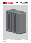
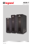
KEOR T
Installation Manual
LE07544AB
KEOR T
EN
2
ENGLISH
6
Installation Manual
KEOR T
Important Notices!
Thank you for choosing LEGRAND UPS System to supply your Critical Application.
This manual contains important information about commissioning, usage and technical properties of the
UPS. It also contains safety information for operator and instructions to secure your critical load. Applying
the recommendation detailed in this manual is necessary to use UPS safely and correctly.
Read the manual completely before working on this equipment!
Keep this manual in UPS’s front cover’s pocket for easy consultation!
Reproduction, adaptation, or translation of this manual is prohibited without
prior written permission of LEGRAND Company, except as allowed under the
copyright laws.
The manufacturer reserves the rights to change the technical specifications
and design without notice.
LEGRAND reserves the rights to change the information in this document
without notice.
Refer to http://ups.legrand.com/ web site to download last release and
translations.
Units that are labelled with a CE mark comply with the Standard: EN 62040-1 and EN 62040-2.
3
Description of the Symbols Used in the Manual
This symbol points out the instructions which are especially important.
This symbol points out the risk of electric shock if the following instruction is
not followed.
This symbol points out the instructions, which may result with injury of the
operator or damage of the equipment if not followed.
All packing material must be recycled in compliance with the laws in force in
the country where the system is installed.
Description of the Abbreviations Used in the Guide
UPS: Uninterruptible Power Supply
ESD: Emergency Switching Device
RS232: Serial Communication Protocol
RS485: Serial Communication Protocol
MODBUS: Modicon Communication Protocol
SNMP: Simple Network Management Protocol
V: Volt
A: Ampere
P: Power
For Mains Supply, Auxiliary Mains Supply, Output, Battery Circuit Breaker and Maintenance Bypass
Circuit Breaker;
“ON”: Closing the Circuit
“OFF”: Opening the Circuit
4
Installation Manual
KEOR T
Battery Fast Fuses
Installation & Operating Manuals
5
Index
1 Foreword
1.1
1.2
Overview
Manual
2 Warranty
2.1
2.2
Terms of Warranty
Out of Warranty Terms and Conditions
7
7
9
9
9
3 Safety
10
3.1
3.2
3.3
3.4
3.5
10
10
11
12
12
Description of the Symbols Used on the Labels Applied to the UPS
Individual Protective Gear
Important Notice for UPS
Important Notice for Battery
Emergency interventions
4 Requirement
4.1 Transportation
4.2 Placement
4.3 Storage
4.4. Electrical Requisites
5 Installation
5.1
5.2
5.3
Models and Dimensions
Unpacking Procedure
Installation Procedures and Instructions
5.3.1. Power Connections for Single Systems
6 Communication
6.1.
6.2.
6.3.
6.4.
6.5.
6
7
Serial Communication (RS232)
Internal SNMP Communication
Emergency Switching Device and Generator Connections
Dry Contacts
RS485
Appendix-1: Technical Specifications
Appendix-2: Modbus List
Appendix-3: Description of UPS and Block Diagram
13
13
13
15
15
18
18
19
20
21
47
48
49
50
51
52
53
55
57
Installation Manual
KEOR T
1. Foreword
1.1. Overview
Thank you for choosing LEGRAND UPS KEOR T product.
KEOR T has been designed with advanced technologies and the latest components generation; realized to satisfy
both users and installers in their operational needs of high availability and performance.
This UPS aims to be efficient, functional, safe and very easy to install and use. LEGRAND has studied the best way
to reconcile high-tech performance and ease of use, making “user friendly” technologically advanced products.
KEOR T supplies maximum protection and power quality for any type of IT load, tertiary application, lighting or
building. Furthermore, standards deployed by Legrand for R&D, supplier selection and manufacturing complies
with the highest quality standards. This product is manufactured in an ISO 9001 & ISO14001 certified factory in full
compliance with the eco-design laws. The UPS KEOR T system is made in compliance with the existing European
Community directives and with the technical standards in force to comply with CE marking as certified by the
Declaration of Conformity issued by the Manufacturer.
Technology & Architecture
A special feature of KEOR T is Online Double Conversion Operation (VFI-SS-111 as defined by the reference
standard EN 62040-3) based on the capacity to supply a voltage that is perfectly stabilized in frequency and
amplitude, even in event of extreme alterations of mains power supply.
The 3-Level Switching Technology used in this product is the latest solution to provide high energy efficiency even
with low load conditions.
The energy efficiency performance of KEOR T surpasses the minimum requirements defined by the Code of
Conduct on Energy efficiency and Quality of European of AC UPS defined by EC.
KEOR T represents the best solution combining high performance, low management costs and ease of operation
and maintenance:
• Dual Input
• User friendly touch screen design
• UPS via LED bar (with traffic light coding) gives an immediate diagnosis of the system under any conditions.
• Internal Battery option as well as wide range external battery cabinets.
• Isolation transformer can be mounted inside UPS cabinet upon request.
• Integrated Maintenance Bypass
• Parallelable to increase the power
• Availability of different communication types
1.2. Manual
• The purpose of this manual is to provide indications for using the equipment safely and to carry out first level of
troubleshooting.
• This manual is addressed to persons already educated on precautions to adopt in face of electrical hazard
• This manual is addressed to “User“, generic term to identify all persons that will have the need and / or obligation
to provide instructions or operate directly this UPS equipment
• Adjustments, preventive and curative maintenance jobs are not dealt with in this manual as they are reserved
exclusively to skilled and authorized Legrand UPS Technical Service Engineers.
7
• The intended use and configurations envisaged for the equipment are the only ones allowed by the Manufacturer;
do not attempt to use the equipment in disagreement with the indications given. Any other use or configuration
must be agreed and written by the Manufacturer, in such a case, will be an enclosure to the manual.
• For its use the user must also comply with the specific laws in force that exist in the country where the equipment
is installed. Reference is also made in this manual to laws, directives, etc., that the user must know and consult in
order to fulfil the purposes established by the manual.
• If information is exchanged with the Manufacturer or assistance personnel authorized by the former, please refer
to the equipment’s rating plate data and serial number.
• The manual must be kept for the equipment’s useful life cycle and, if necessary (e.g. damage which prevents it
being consulted even partially) the user must ask the Manufacturer for a new copy, quoting the publishing code
on the cover.
• The manual reflects the state of the art at the moment the equipment was put on the market, of which it is an
integral part. The publication complies with the directives in force at such a date. The manual cannot be considered
inadequate if updates of standards or changes are made to the equipment.
• Any integration to the manual which the Manufacturer deems fitting to send to the users must be kept with the
manual, becoming an integral part of it.
• The Manufacturer is available to its clientele to provide additional information and will take into consideration
any suggestions made to improve this manual to bring it even closer to the requirements for which it was drawn
up.
• If the equipment is sold, which always includes handing over this operating manual, the primary user must
notify the Manufacturer, giving him the address of the new user so the latter can be reached if there are any
communications and/or updates deemed indispensable.
Read the manual completely before working on this equipment!
Keep this manual in UPS’s front cover’s pocket for easy consultation!
Reproduction, adaptation, or translation of this manual is prohibited without prior written
permission of LEGRAND Company, except as allowed under the copyright laws.
The manufacturer reserves the rights to change the technical specifications and design
without notice.
LEGRAND reserves the rights to change the information in this document without notice.
Refer to http://ups.legrand.com/ web site to download last release and translations.
Units that are labelled with a CE mark comply with the Standard: EN 62040-1 and EN 62040-2.
8
Installation Manual
KEOR T
2. Warranty
2.1. Terms of Warranty
• Warranty is defined by General Conditions of Sale and Delivery.
• The UPS including all the internal parts is under the warranty of LEGRAND.
• If the UPS malfunctions because of component, manufacturing or installation (if it’s done by authorized
LEGRAND UPS Technical Service Personnel) problems during the warranty period, the UPS will be repaired (spares
and labour) by the Manufacturer under warranty.
2.2. Out of Warranty Terms and Conditions
This Warranty does not apply if:
• UPS not commissioned or maintained by an authorized LEGRAND UPS Technical Service staff or an authorized
LEGRAND distributor Technical Service staff
• UPS not used according the terms of operating and installation manual
• Product serial number label has been removed or lost
This Warranty does not cover any defects or damages caused by:
• Neglect, accident, misuse, misapplication
• Failure due to fortuitous circumstances or force majeure (lightning, floods…etc.),
• Unloading and transportation damage and failures after delivery,
• Damage or injuries caused by negligence, lack of inspection or maintenance, or improper use of the products,
• Faulty electrical wiring,
• Defects arising either from designs or parts imposed or supplied by the purchaser,
• Defects and damage by fire and lightning,
• Failures due to modification in the products without LEGRAND approval,
• Improper installation, testing, operation, maintenance, repair, alteration, adjustment, or modification of any kind
by unauthorized personnel,
The Manufacturer will repair the device in such cases for a fee and is not responsible for the shipment of the
equipment.
The Battery warranty does not apply if the temperature in the room exceeds 25 °C.
Extended battery warranty does not apply if:
• UPS has not been commissioned
• A yearly preventive maintenance visit has not been performed
By an authorized LEGRAND UPS Technical Service staff or authorized LEGRAND distributor Technical Service staff.
The UPS may contain batteries that should be recharged 24Hours min after 6 month storage duration to avoid
deep battery discharge. Warranty cannot apply on batteries that have suffered of deep discharge.
9
3. Safety
Information related to safety of the UPS, battery, load and the user is summarized
below. But the equipment should not be installed before reading the manual
completely
3.1. Description of the Symbols Used on the Labels Applied to the UPS
PE: Protective Earth
PB: Protective Bonding
Danger! High Voltage (Black/Yellow)
This symbol points out the instructions, which may result with injury of the operator
or damage of the equipment if not obeyed.
3.2. Individual Protective Gear
There is a high risk of electrical shock with the equipment as well as a considerable short circuit current.
When installing and servicing the equipment it is absolutely forbidden to work without the protective
gear mentioned in this paragraph.
The personnel who are going to work with the equipment for installation or maintenance jobs must not
wear clothes with baggy sleeves or laces, belts, bracelets or other metal items that could be a hazard
source.
10
The following indications summarize the protective gear to wear.
Accident and spark proof footwear with rubber sole and reinforced toe
Use : always
Installation Manual
KEOR T
Waterproof rubber gloves
Use : always
Protective gear
Use : always
Protective glasses
Use : always
3.3. Important Notice for UPS
• The equipment may only be installed and commissioned by authorized LEGRAND UPS Technical Service
Personnel.
• This manual contains important instructions that you should follow during installation and maintenance of
the UPS and batteries. Please read all instructions before installing the equipment and save this manual for
future reference.
• Not obeying the instructions written on this manual which may result with possible injury of the operator or
damage of the equipment.
• The equipment shall be packed and fixed properly during transportation to avoid fall down and proper
equipment should be used for transportation. Never transport in horizontal position.
• The UPS must always stands in a vertical position. Make sure that the floor can support the weight of the
system.
• Connect the PE ground connector before connecting any other cable.
• UPS is designed for indoor use. To reduce the risk of fire or electric shock, install this UPS in a temperature and
humidity controlled indoor environment, free of conductive contaminants. Ambient temperature must not
exceed 40°C (104°F). Do not operate near water or excessive humidity (95% maximum without condensation).
• UPS requires 3Ph-N+PE input connection.
• Do not connect the output neutral to the protective ground or protective bonding (except the TNC Option).
Keor T does not modify the neutral arrangements of the system; the use of an isolation transformer is required
should it be necessary to modify the neutral arrangements downstream Keor T.
• KEOR T must be protected from voltage surge with devices that are suited to the installation; the mains
voltage surge must be limited to 2kV. These protective devices must be sized to take into account all the
installation parameters (geographical position whether or not there is a lightning rod, whether or not there
are other suppressors in the electrical installation, etc )
• Even when connections removed, residual voltages of capacitors and/or high temperature may exist on
connection terminals and inside the UPS. Before working on terminals, check between all the terminals
included PE that no hazardous voltages exist.
• The connections shall be made with cables of appropriate cross-section in order to prevent the risk of fire. All
cables shall be of insulated type and shall not be laid out on the walking path of the persons.
11
• According to IEC 62040-2; this is a product for commercial and industrial application. In the second
environment installation restrictions or additional measures may be needed to prevent disturbances.
• Contact your local recycling or hazardous waste center for information on proper disposal of the used battery
or UPS.
• Make sure that the UPS is not overloaded to provide a higher quality supply to the loads.
• In case of an extraordinary situation (damaged body, cabinet or connections, penetration of foreign materials
into the body or cabinet etc.) de-energize the UPS immediately and consult to the LEGRAND Technical
Assistance Center.
• When used for particular applications such as life support systems or any other application where product
failure is likely to cause substantial harms to person, we would advise you to contact LEGRAND UPS to confirm
the ability of these products to meet the requested level of safety, performance, reliability and compliance
with applicable laws, regulations and specifications.
3.4. Important Notice for Battery
• The batteries may only be installed and commissioned by authorized LEGRAND UPS Technical Service
Personnel.
• Make sure that the battery qty is proper for the unit and they are same type and capacity. Otherwise danger
of explosion and fire is within the bounds of possibility.
• Do not dispose of batteries in a fire. The batteries may explode.
• Do not open or mutilate batteries. Released electrolyte is harmful to the skin and eyes. It may be toxic.
• In case of electrolyte in contact with skin, immediately wash the contaminated skin with water.
• Replaced batteries must be disposed of at authorized battery waste disposal centers.
• A battery can present risk of electric shock and high short circuit currents.
The following precautions should be observed when working on batteries;
• Remove rings, watches, necklaces, bracelets and all metal objects.
• Only use tools with insulated handles.
• Wear rubbers gloves and a rubber apron when handling batteries.
• Do not lay tools or metal parts on top of batteries.
• Eye protection should be worn to prevent injury from accidental electrical arcs.
• Before a maintenance or repair work on the UPS;
• Switch the input, output and battery circuit breakers (Q1, Q2 and F5) to “OFF” position.
• If UPS has internal batteries; Remove and isolate + battery (red) and N battery neutral (blue) cables.
• If UPS has external batteries; also switch the circuit breakers of the battery cabinet to “OFF” position.
• Determine if the battery is inadvertently grounded. If inadvertently grounded; remove source of ground.
Contact with any part of a grounded battery can result in electrical shock.
• Battery fuses shall only be replaced with the same rating and type which came along with the UPS.
3.5. Emergency interventions
The following information is of a general nature. For specific interventions please consult the laws existing in
the country where the equipment is installed.
First aid interventions
If any first aid intervention is required, comply with company rules and traditional procedures.
Fire-prevention measures
Never use water to extinguish fire but only the extinguishers designed specifically for electronic equipment
or battery fires. 12
4. Requirement
4.1. Transportation
Installation Manual
KEOR T
The UPS must be placed and stand in a vertical position throughout the transportation.
Use suitable equipment to remove the UPS from the pallet.
The equipment shall be packed properly during transportation. Therefore it is
recommended to keep the original package for future need.
All packing material must be recycled in compliance with the laws in force in the
country where the system is installed.
4.2. Placement
This product meets the safety requirements for devices to be operated in restricted access locations according to EN
60950-1 safety standard, which states that the owner should guarantee the following:
• Access to the equipment can only be gained by service persons or by users who have been instructed about the
reasons for the restrictions applied to the location and about any precautions that shall be taken and,
• Access is through the use of a tool or lock and key, or other means of security and is controlled by the authority
responsible for the location.
• UPS is not designed for outdoor application.
• The equipment and the batteries should not be exposed to direct sunlight or placed near to a heat source.
• Recommended operating temperature and humidity values are listed on the Appendix-1 Technical Specifications.
• Avoid dusty environments or areas where dust of conductive or corrosive materials is present.
• The connection and the circuit breakers are at the front of UPS. Leave access at the front of the UPS for maintenance.
(Refer to Figure.4.2-4)
• Air outlets of the UPS are at the front, back and on both sides. Leave access at the front side, back side and from both
lateral sides for ventilation and battery replacement. (Refer to Figure.4.2-1, 4.2-2, 4.2-3 and 4.2-4)
• Recommended environmental humidity condition is between 20-95% (non-condensing).
Environment Requirement
Model (kVA)
Max. dissipation at no load
Max. dissipation at full load
10
15
20
30
40
60
(W)
258
360
440
557
810
900
(BTU)
880
1228
1500
1900
2764
3070
(W)
470
705
940
1410
1880
2820
1604
2406
3207
4811
6415
9622
(BTU)
Storage temperatures
-25/+55 °C (-13/131 °F) (15-25 °C for maximum battery life)
Working temperature
0/40 °C (32/104 °F) (15-25 °C for maximum battery life)
Maximum relative humidity
95% max. without condensation
Maximum altitude without derating
1.000 m (3.300 ft)
Degree of protection
Colour cabinet
IP 20 (other IP as option)
RAL 7016@enclosure RAL 9005@front door metal
Table.1
13
Figure.4.2-1
Figure.4.2-2
Figure.4.2-3
Air conditioning
Ventilation
Direction of ventilation is front/sides to back.
The room should be equipped with ventilation system or air conditioning to collect warm air
from the top of the room and provide cool air at the bottom.
Figure.4.2-4
ROOM LAYOUT RECOMMENDATION TABLE (for UPS with Internal Battery)
14
A (mm)
B (mm)
C (mm)
700
500
250
D (mm)
10-30kVA : 500 (for maintenance and internal battery installation)
40-60kVA : 700 (for maintenance and internal battery installation)
Ensure the stability of UPS without internal battery and take necessary precautions.
Installation Manual
KEOR T
The UPS should be mounted on a concrete surface and non-combustible surface.
In order to profit from optimal ventilation, the side panels must remain in place for UPS
with internal battery.
Optimal battery life time is reached when battery ambient temperature is kept between
15°C and 25°C. Operating battery at 30°C ambient temperature compared to 20°C will
divide by factor 2 battery life time. Room thermal management as specified above is
then necessary to avoid battery life time reduction. The Battery warranty does not apply
if the temperature in the room exceeds 25°C.
4.3. Storage
Please store the UPS in an environment where the temperature is between -250C + 550C, no receipt of
direct sunlight, far from the heating, in a dry place.
Environmental humidity must be between 20-95% (non-condensing).
Recommended storage temperature, humidity and altitude values are listed on the Appendix-1 Technical
Specifications section.
If the batteries will be stored for longer than 6 months, they shall be charged periodically. Charge period
depends on the storage temperature, as shown below:
• Every 9 months if the temperature is below 20°C,
• Every 6 months if the temperature is between 20°C and 30°C,
• Every 3 months if the temperature is between 30°C and 40°C,
• Every 2 months if the temperature is over 40°C
For long storage duration; please follow up the instructions of installation described in Section 5, start-up
UPS described in Section 6 and charge the batteries at least 10 hours.
4.4.. Electrical Requisites
The installation must comply with national installation regulations.
The electrical distribution panels for common mains supply voltage and auxiliary mains supply voltage
inputs must have a protection and disconnection system. Disconnection devices used in these panels
shall disconnect all line conductors simultaneously. The following table shows the recommended size
of common mains supply voltage and auxiliary mains supply voltage input protection devices (thermal,
magnetic and differential) and the cable cross-sections for the loads.
When dual inputs is used:
• Separate Neutral conductor is necessary to be supplied for each input: Common
Mains Input and Auxiliary Mains Input
• The two inputs should be supplied by the same MV/LV transformer source. If this is
not the case, an insulation transformer should be added in the auxiliary mains line
upstream the UPS.
• Separate protection is necessary for each input line.
15
Installation Parameters
Model (kVA)
10
15
10
15
20
30
40
60
Rated output active power (kW)
9
13,5
18
27
36
54
Rated input current (A) at 400V nominal input voltage
14
21
28
42
57
84
Phase in/out
20
30
40
60
3Ph+N+PE / 3Ph+N+PB
Rated output apparent power (kVA)
Maximum input current (A) at 340V input voltage + full load + battery charging
18
26
36
54
72
105
Rated bypass current (A) at 400V nominal input voltage
15
22
29
44
58
87
Maximum bypass current (A) at 400V, 125% overload 10 min
19
28
36
55
73
109
Inverter output current @ 400V (A)
15
22
29
44
58
87
19
28
36
55
73
109
10
min
11,3
16,9
22,5
33,8
45
67,5
1 min
13,5
20,3
27
40,5
54
81
D curve circuit breaker (A) (3 or 4-pole according neutral system)
20
25
40
50
63
100
GG fuse (A)
20
25
40
50
63
100
40
50
63
Maximum Inverter output current (A) at 400V, 125% overload 10 min
Overload tolerated by the inverter (with mains power present) (kW)
Recommended Protection Devices - Rectifier/Mains Supply -*
Recommended Protection Devices – General Bypass/Auxiliary Mains Supply –*
20
25
Maximum I2t supported by the bypass (A2s) (10ms)
D curve circuit breaker (A) (3 or 4 pole according neutral system)
6700
11200
15000
25300
100
Icc max (A)
1200
1500
1700
2300
25
32
Protection Devices – Battery Fast Fuse –
Ferrule style high speed fuses and with indicating striker
(High Speed FWP Bussmann Fuse 22x58mm 690VAC (IEC)) (A)
50
63
80
100
≤6
≤10
≤13
≤13
≤20
≤25
Recommended Protection Devices – Output –
C curve circuit breaker (A) (3 or 4 pole according neutral system)
≤3
≤4
B curve circuit breaker (A) (3 or 4 pole according neutral system)
≤6
≤8
Maximum inverter short circuit current for 50 ms: IK1=IK2=IK3 =IF
2.1xIn
Max. Cable Cross-Section for Terminals**
Rectifier (mm²)
35
General Bypass (mm²)
35
Battery (mm²)
16
Output (mm²)
35
Neutral (mm²)
35 (Battery Neutral: 16)
35
Protective Earth/Bonding
Recommended cross section for ground wire
at least half of the section of cable phases AND
shall comply with the standards of the country
(for example NFC 15100 in France).
Leakage Current Protection ***
Minimum 300 mA delayed (Type-B). When used,
the residual current earth leakage protection
system must be common for the two AC inputs
(common & auxiliary mains) and installed
upstream.
Table.2
16
35
*Rectifier protection alone should only be considered in the event of separate inputs; if the bypass and
rectifier inputs are combined, the general input protection rating (bypass + rectifier) must reflect the
recommended bypass or general protection rating.
*Recommended discrimination of UPS downstream distribution with inverter short-circuits current (battery
mode).
Installation Manual
KEOR T
** Cables must be selected 1.2 times larger than the recommended size for parallel topologies.
***Must be selective with residual current circuit breakers downstream of the UPS connected to the UPS
output. If the bypass network is separate from the rectifier circuit, or in the event of parallel UPS, use a single
residual current circuit breaker upstream of the UPS.
If the loads generates high rate of third harmonic current ( THDI > 33% ), the
current on the common mains supply voltage and auxiliary mains supply voltage
input and output neutral conductors may have a value that is 1.5-2 times the
phase value during operation. In this case, size the neutral cables and the input/
output protection adequately.
17
5. Installation
When the UPS is delivered, examine the packaging and product carefully to see if any damage occured during transport.
If either possible or ascertained damage is found report it immediately to:
• the carrier;
• LEGRAND Technical Assistance Center.
Make sure that the unit received corresponds to the material specified on the delivery document. The UPS Keor T
packaging protects the equipment against mechanical and environmental damages. For greater protection it is also
wrapped in a transparent film.
Check if the following are provided with the equipment
• UPS
• Operating Manual
• Installation Manual
• Key for door
• Battery fuses (three pieces)
• Plinths
Before the installation, please check if your UPS is customized following your special
requirements (if any).
5.1. Models and Dimensions
UPS Type
18
Dimension (HxWxD) (mm)
Net Weight (Kg)
Internal Batteries Type
UPS KEOR T 10 KVA 1345H X
1345 x 400 x 800
121
No battery
UPS KEOR T 10 KVA 1345H 1
1345 x 400 x 800
264
60 blocks 7 AH
UPS KEOR T 10 KVA 1345H 2
1345 x 400 x 800
278
60 blocks 9 AH
UPS KEOR T 10 KVA 1650H 3
1650 x 400 x 800
426
120 blocks 7 AH
UPS KEOR T 10 KVA 1650H 0
1650 x 400 x 800
140
No battery
UPS KEOR T 10 KVA 1345H TX
1345 x 400 x 800
240
No battery
UPS KEOR T 15 KVA 1345H X
1345 x 400 x 800
132
No battery
UPS KEOR T 15 KVA 1345H 1
1345 x 400 x 800
272
60 blocks 7AH
UPS KEOR T 15 KVA 1345H 2
1345 x 400 x 800
290
60 blocks 9 AH
UPS KEOR T 15 KVA 1650H 3
1650 x 400 x 800
428
120 blocks 7 AH
UPS KEOR T 15 KVA 1650H 0
1650 x 400 x 800
151
No battery
UPS KEOR T 15 KVA 1345H TX
1345 x 400 x 800
250
No battery
UPS KEOR T 20 KVA 1345H X
1345 x 400 x 800
144
No battery
UPS KEOR T 20 KVA 1345H 1
1345 x 400 x 800
286
60 blocks 7AH
UPS KEOR T 20 KVA 1345H 2
1345 x 400 x 800
304
60 blocks 9 AH
UPS KEOR T 20 KVA 1650H 3
1650 x 400 x 800
490
120 blocks 9 AH
UPS KEOR T 20 KVA 1650H 0
1650 x 400 x 800
162
No battery
UPS KEOR T 20 KVA 1345H TX
1345 x 400 x 800
255
No battery
UPS KEOR T 30 KVA 1345H X
1345 x 400 x 800
148
No battery
UPS KEOR T 30 KVA 1345H 1
1345 x 400 x 800
309
60 blocks 9 AH
UPS KEOR T 30 KVA 1650H 2
1650 x 400 x 800
455
120 blocks 7 AH
UPS KEOR T 30 KVA 1650H 3
1650 x 400 x 800
491
120 blocks 9 AH
UPS KEOR T 30 KVA 1650H 0
1650 x 400 x 800
169
No battery
UPS KEOR T 30 KVA 1345H TX
1345 x 400 x 800
285
No battery
UPS KEOR T 40 KVA 1650H X
1650 x 600 x 900
241
No battery
UPS KEOR T 40 KVA 1650H 1
1650 x 600 x 900
552
120 blocks 7 AH
UPS KEOR T 40 KVA 1650H 2
1650 x 600 x 900
588
120 blocks 9 AH
UPS KEOR T 40 KVA 1650H 3
1650 x 600 x 900
764
180 blocks 9 AH
UPS KEOR T 40 KVA 1650H 0
1650 x 600 x 900
241
No battery
UPS KEOR T 40 KVA 1650H TX
1650 x 600 x 900
525
No battery
UPS KEOR T 60 KVA 1650H X
1650 x 600 x 900
276
No battery
UPS KEOR T 60 KVA 1650H 1
1650 x 600 x 900
625
120 blocks 9 AH
UPS KEOR T 60 KVA 1650H 2
1650 x 600 x 900
799
180 blocks 9 AH
UPS KEOR T 60 KVA 1650H 0
1650 x 600 x 900
276
No battery
UPS KEOR T 60 KVA 1650H TX
1650 x 600 x 900
575
No battery
Table.3
5.2. Unpacking Procedure
Figure.5.2-1
This side parts prevent the transpallet
to damage the UPS cabinet
Installation Manual
KEOR T
Remove the wrap and the package.
Figure.5.2-2
Figure.5.2-3
Place UPS in the installation area.
19
Figure.5.2-4
Remove the side parts which prevent the transpallet to damage the UPS.
Unload the UPS from the pallet.
It is recommended to store the original UPS packaging for future needs.
5.3. Installation Procedures and Instructions
The equipment may only be installed and commissioned by authorized LEGRAND
UPS Technical Service Staff or authorized LEGRAND distributor Technical Service
Staff.
When the UPS is brought from a cold place to a warmer place, humidity of the air may
condensate in it. In this case, wait minimum for 2 (two) hours before powering the UPS.
KEOR T must be protected from voltage surge with devices that are suited to the installation;
the mains voltage surge must be limited to 2kV. These protective devices must be sized to take
into account all the installation parameters (geographical position whether or not there is a
lightning rod, whether or not there are other suppressors in the electrical installation, etc )
Do not connect the output neutral to the protective ground or protective bonding (except
the TNCOption). Keor T does not modify the neutral arrangements of the system; the use of an
isolation transformer is required should it be necessary to modify the neutral arrangements
downstream Keor T.
Power cables and communication cables shall be installed on trays according to the standards of the country.
20
5.3.1. Power Connections of Single Systems
Make sure that all circuit breakers are “OFF” before starting with the installation.
Installation Manual
KEOR T
The power screw terminals are located on the lower front side of the UPS.
Firstly, open the UPS door, screw out of the metal cover, afterwards open plastic cover of terminals.
After the covers are removed, the cables shall be passed through the hole under the terminals.
After all connections done, replace the covers in order.
Figure.5.3.1-1
Figure.5.3.1-2
Figure.5.3.1-3
10-30kVA KEOR T
Figure.5.3.1-5
Figure.5.3.1-4
40-60kVA KEOR T
21
Figure.5.3.1-6
Power Cables Path
Figure.5.3.1-7
Communication Cables Path
Figure.5.3.1-8
Fix the plinths delivered with the UPS after all cable installation done
22
Keor T 10-30kVA (3Ph Input – 3Ph Output) Circuit Breakers
Figure.5.3.1-9
Q1: Common Mains Supply Circuit Breaker
Q2: Output Circuit Breaker
Q3: Maintenance Bypass Circuit Breaker
Installation Manual
KEOR T
Q4: Auxiliary Mains Supply Circuit Breaker
F5: Battery Fast Fuse
Q6: Inrush Circuit Breaker
23
24
X1 MAINS SUPPLY
Terminal
Bridges
X1/L1
X1/L2
X1/N
PE
X5 EXTERNAL BATTERY PB
X1/ L3
-
N
+
cd X8 External Battery Breaker Position Feedback
a b X6 External Maintenance Bypass
123 X7 External battery temperature sensor
PB L1 L2 L3 N X2 OUTPUT
Keor T 10-30kVA (3Ph Input – 3Ph Output)
Connection if the MAINS and AUX Supply are connected in COMMON
Figure.5.3.1-10
X4 AUXILIARY SUPPLY
X1 MAINS SUPPLY
X4/L2
PE
PB
X5 EXTERNAL BATTERY PB
X4 /N
X1/N
X4/L3
X1/ L2 X1/ L3
X4/L1
X1/ L1
-
N
+
External battery
temperature sensor
cd X8 External Battery Breaker Position Feedback
a b X6 External Maintenance Bypass
123 X7
PB L1 L2 L3 N X2 OUTPUT
Keor T 10-30kVA (3Ph Input – 3Ph Output)
Connection if the MAINS and AUX Supply are connected SEPARATELY
Installation Manual
KEOR T
Figure.5.3.1-11
25
Keor T 10 -30kVA ( 3Ph Input - 3Ph Output) With Output Isolation Transformer
Connection if the MAINS and AUX Supply are connected in COMMON
Figure.5.3.1-12
26
Keor T 10-30kVA (3Ph Input – 3Ph Output) With Output Isolation Transformer
Connection if the MAINS and AUX Supply are connected SEPARATELY
Figure.5.3.1-13
Installation Manual
KEOR T
27
Keor T 40-60kVA (3Ph Input – 3Ph Output) Circuit Breakers
Figure.5.3.1-14
Q1: Common Mains Supply Circuit Breaker
Q2: Output Circuit Breaker
Q3: Maintenance Bypass Circuit Breaker
28
Q4: Auxiliary Mains Supply Circuit Breaker
F5: Battery Fast Fuse
Q6: Inrush Circuit Breaker
Keor T 40-60kVA (3Ph Input – 3Ph Output)
Connection if the MAINS and AUX Supply are connected in COMMON
Installation Manual
KEOR T
Figure.5.3.1-15
29
Keor T 40-60kVA (3Ph Input – 3Ph Output)
Connection if the MAINS and AUX Supply are connected SEPARATELY
Figure.5.3.1-16
30
Keor T 40-60kVA (3Ph Input – 3Ph Output) With Output Isolation Transformer
Connection if the MAINS and AUX Supply are connected in COMMON
Figure.5.3.1-17
Installation Manual
KEOR T
31
Keor T 40-60kVA (3Ph Input – 3Ph Output) With Output Isolation Transformer
Connection if the MAINS and AUX Supply are connected SEPARATELY
Figure.5.3.1-18
32
Connections shall be made in the following order;
5.3.1.1. Earth Connection
Installation Manual
KEOR T
The device shall be earthed for a safe and reliable operation. Connect the PE/
PB ground terminals before connecting any other cable.
Figure.5.3.1.1-1
Input Mains Supply’s Protective Earth terminal
PE of the UPS shall be connected to the ground
with a low impedance connection.
As the Auxiliary Supply Protective Bonding PB
and Input Mains Supply’s Protective Earth PE
terminals are short-circuited inside UPS, it is
not needed any connection.
Load ground should be connected to output
X2/PB terminal of the UPS.
If there is an external battery cabinet present,
it should be grounded via battery X5/PB terminal of the UPS.
5.3.1.2. Mains Supply (Rectifier) Connection
The installation and adjustment of distribution panel should be done by specialized
technician.
Electrical Characteristics - Rectifier Input
Model (kVA)
10
Rated mains supply voltage (V)
15
20
30
40
60
400 (3Ph+N+PE)
Voltage tolerance (V) (ensuring battery recharge)
208-459 (at half Load, without battery recharge)
338-459 (at full Load, with battery recharge)
Rated frequency (Hz)
50/60
Frequency tolerance (Hz)
from 45 to 65
Power factor (input at full load and rated voltage)
≥ 0,99
Table.4
33
Connect the phase cables to X1 MAINS SUPPLY:
X1/L1 - X1/L2 - X1/L3 terminals, the neutral to X1
MAINS SUPPLY: X1/N terminal.
Cables must be protected by fuses or MCCB, refer
to Section 4.4
If auxiliary supply exists, remove all bridges. When used, the residual current
earth leakage protection system must be common for the two AC inputs and installed upstream.
According to EN 62040-1, the user should place a warning label on the input distribution panel and the other primary power isolators, in order to prevent the risk of voltage
backfeed.
This label is supplied with the Installation Manual. It indicates:
Risk Of Voltage Backfeed
• Isolate Uninterruptable Power Supply before working on this circuit.
• Then check for Hazardous Voltage between all terminals including the protective
earth (PE).
WARNING
WARNING
RISK OF BACKFEED
EN
RISQUE DE RETOUR DE TENSION
Before working on this circut
isotale Uninterruptible Power System (UPS),
Then check for hazardous Voltage between
all terminals includig the protective earth
(PE)
FR
WARNING
WARNING
RÜCKSPANNUNG RISIKO
BACK FEED RISCHIO
IT
Avant de travailler sur le circuit électrique
İsoler I’ alimentation sans interruption (ASI)
Puis vérifier s’ il y a présense de tension
dangereuse entre toutes les bornes incluat la
connexion de terre.
DE
Prima di intervenire su questo circuito
isolare I’UPS dalla rete .
Controllare la prensenza di tensioni
pericolose tra tutti i terminali
..
Bevor Sie einen Eingriff am Grat
vornehmen trennen Sie die USV - Anlage
vom Netz.
..
Überprüfen Sie auf geharlichte spanunngen
zwischen den Anschlüssen und der
Shutzerde (PE).
5.3.1.3. Auxiliary Supply Connection
Electrical Characteristics - Bypass
Model (kVA)
10
Bypass frequency slew rate
15
20
30
40
60
2 Hz/s settable from 1 to 3 Hz/s
Bypass rated voltage
Nominal output voltage ±18% (settable)
Bypass rated frequency
50/60 Hz (selectable)
Bypass frequency tolerance
±3Hz
Table.5
34
Connect the phase cables to X4 AUXILIARY SUPPLY: X4/L1 - X4/L2 - X4/L3 terminals, the neutral to
X4 AUXILIARY SUPPLY: X4/N terminal.
Cables must be protected by fuses or MCCB, refer to Section 4.4
If auxiliary supply exists, remove all bridges.
Installation Manual
KEOR T
5.3.1.4. Battery Connection
You may find more information about Keor T Models and Battery capacity in Section 5.1. Models and
Dimensions.
Danger of explosion and fire if the batteries of the wrong type are used.
The batteries must be charged min. 10 hours before first-use.
Battery fast fuses shall only be replaced with fuses of the same type and rating.
Do not use internal and external battery together!
Internal Battery Connection:
If UPS with internal battery; there are no X5 and X8 terminals mounted on the UPS.
If the batteries are already built-in inside the UPS cabinet; in order
to avoid any danger during transportation, some battery connections are left unconnected.
Thus, remove the left & right covers of UPS; disconnect the side
panels’ earth cables. Connect the unconnected battery cables to the related battery connectors. The unconnected cables are labelled. You may find detailed information about battery connection as follows.
There is no need for any further connection, so reconnect the side panels’ earth cables and replace the
covers.
LETHAL VOLTAGE of nominal 720 VDC is present when the external battery connections are made.
35
Keor T 10-30kVA 1x60pcs 7-9Ah BATTERY WIRING DIAGRAM
Figure.5.3.1.4-1
36
Keor T 10-30kVA 2x60pcs 7-9Ah BATTERY WIRING DIAGRAM
Installation Manual
KEOR T
Figure.5.3.1.4-2
37
Keor T 40-60kVA 2x60pcs 7-9Ah BATTERY WIRING DIAGRAM
Figure.5.3.1.4-3
38
Keor T 40-60kVA 3x60pcs 7-9Ah BATTERY WIRING DIAGRAM
Installation Manual
KEOR T
Figure.5.3.1.4-4
39
External Battery Connection:
External Battery Connection:
Keor T Battery Cabinet comes with the following cables;
• 3 meters 4 x 16mm² power cables for battery connection
• 4 meters 2 x 0.5mm² double insulated cables for external battery breaker position feedback signal
• 4 meters 3 x 1.5mm² double insulated cables for external battery cabinet temperature sensor signal
• 3 x Field-mountable Battery Fast Fuses (rating & type depending on the cabinet model)
• 2.9 meters spiral for power cables for protection
If battery cabinets not supplied by LEGRAND, it is the installer’s responsibility
to check the electrical compatibility and the presence of appropriate protection devices between the cabinet and Keor T.
Read the KEOR T Service Manual carefully for Battery Wiring Diagram in
External Battery Cabinet!
To avoid risk of electromagnetic interference separate the battery cables from
Input and Output cables.
LETHAL VOLTAGE of nominal 720 VDC is present when the external battery
connections are made.
For UPS and External Battery Cabinet Connections, please follow up the instructions below;
For UPS and External Battery Cabinet Connections, please follow up the instructions below;
• Unplug the cable of Thermal Sensor Board on the UPS.
• Switch all battery cabinets circuit breaker (F5) to “OFF” position.
• Ground: Connect all “PB” on the battery cabinets directly to X5 EXT. BATTERY: “PB” on the UPS.
• Negative String: Connect the “-“on Battery Cabinet #1 to X5 EXT. BATTERY: “-” on the UPS. Connect the
“-“on Battery
Cabinet #2 to X5 EXT. BATTERY: “-” on the Battery Cabinet #1 and so on...
• Positive String: Connect the “-“on Battery Cabinet #1 to X5 EXT. BATTERY: “+” on the UPS. Connect the
“+“on Battery
Cabinet #2 to X5 EXT. BATTERY: “+” on the Battery Cabinet #1 and so on...
• Neutral: Connect the “N “on Battery Cabinet #1 to X5 EXT. BATTERY: “+” on the UPS. Connect the “N“on
Battery
Cabinet #2 to X5 EXT. BATTERY: “N” on the Battery Cabinet #1 and so on...
• External Battery Cabinet Temperature Sensor: Only connect the X7: “X7/1 – X7/2 – X7/3” on the Battery
Cabinet
#1 to X7: “X7/1 – X7/2 – X7/3” on the UPS. (Not extended 25m length is recommended)
• External Battery Breaker Position Feedback:
For one battery cabinet & UPS configuration: Connect the X8: “X8/c – X8/d” on the UPS to X8: “X8/c –
X8/d” on Battery Cabinet #1.
For two battery cabinets & UPS configuration: Connect the X8: “X8/c – X8/d” on the UPS to X8: “X8/c –
X8/e” on Battery Cabinet #1. Connect the X8: “X8/d – X8/e” on Battery Cabinet #1 to X8: “X8/c – X8/d” on
Battery Cabinet #2.
For three battery cabinets & UPS configuration: Connect the X8: “X8/c – X8/d” on the UPS to X8: “X8/c –
X8/e” on Battery Cabinet #1. Connect the X8: “X8/d – X8/e” on Battery Cabinet #1 to X8: “X8/c – X8/e” on
Battery Cabinet #2. Connect the X8: “X8/d – X8/e” on Battery Cabinet #2 to X8: “X8/c – X8/d” on Battery
Cabinet #3.
Battery Fast Fuses: Mount the battery fast fuses into battery fuse holder on the battery cabinet. (fast fuse
indicator side must be placed upper side of the holder) Do not close the battery circuit breaker!
Double check the polarity of battery connection!
40
Figure.5.3.1.4-5
Keor T 10-30kVA
Installation Manual
KEOR T
Figure.5.3.1.4-6
Keor T 10-60kVA
Unplug the cable of Thermal Sensor Board on the UPS
Figure.5.3.1.4-7
Power Connection of Single Battery Cabinet
Figure.5.3.1.4-8
Signal Connection of Single Battery Cabinet
41
Figure.5.3.1.4-9
Power Connection of Two and More Parallel Battery Cabinets
Figure.5.3.1.4-10
Signal Connection of Two Parallel Battery Cabinets
Figure.5.3.1.4-11
Signal Connection of Three and More Parallel Battery Cabinets
42
Make sure that all circuit breakers are at “OFF” position before starting with the
installation.
Electrical Characteristics - Inverter
Model (kVA)
10
Rated output voltage (selectable) (V)
15
20
30
40
Installation Manual
KEOR T
60
400 3Ph+N+PB (380/415 configurable)
Output voltage tolerance
static load ±1%, dynamic load VF-SS-111 compliant
Rated output frequency (Hz)
50/60 Hz (selectable)
Autonomous frequency tolerance
±0.02% on mains power failure
Harmonic voltage distortion
< 2% with linear load, < 4% with non linear load
Table.6
Figure.5.3.1.5-1
Output Connection of UPS without
Isolation Transformer
Figure.5.3.1.5-2
Output Connection of UPS with Isolation
Transformer
Connect the phase cable to X2 OUTPUT: X2/L1 – X2/L2 – X2/L3 terminal and the neutral cable to
X2 OUTPUT: X2/N terminal.
Cables must be protected by fuses or MCCB, refer to Section 4.4
NEUTRAL SYSTEM :
• Versions without internal isolation transformer :
Keor T does not modify the neutral system: output neutral system is the same as
input neutral system. Do not connect the output neutral to the protective ground or
protective bounding (PE or PB).
Installation of an external isolation transformer is required when necessary to modify
the neutral system downstream Keor T.
• Versions with internal isolation transformer :
The output neutral system is IT. Do not connect input neutral to output neutral.
According to the neutral system required downstream Keor T, you may reference
output neutral to protective ground (PE) following your national electric code.
43
For Keor T with internal output isolation transformer model; you can change Neutral Systems IT to TN by making short circuit Output Neutral (X2/N) and Output
Earth (X2/PB).
Fix the short-circuit shunt (supplied in the fast fuses package attached to UPS)
between Output Neutral (X2/N) and Output Earth (X2/PB).
To enable the short circuit protection feature of the UPS, each load should be
supplied through a separate circuit breaker chosen according to the load current.
This may provide quick disconnection of the short circuited load and maintain
operation continuity of the other loads.
Each load should be supplied through separate circuit breaker and the cable
cross section should be chosen according to the load current value.
Make sure that the UPS is not overloaded to provide a higher quality supply to
the loads.
44
5.3.1.6. External Maintenance Bypass Connection
If External Maintenance Bypass would
be used; connect normally open auxiliary contact of External Maintenance
Bypass MCCB on the distribution panel
to terminals a/X6 and b/X6 on UPS.
Installation Manual
KEOR T
5.3.2. Power Connections of Parallel Systems
• The protection devices must be chosen properly as defined in Section 4.4 considering total parallel UPS
power.
• Please check 5.3.1. Power Connections of Single Systems for detailed connection information.
• The cross section and length of the input and output cables must be identical for all units.
• The phase rotation must be the same for each unit connected in parallel and also on any external manual
bypass line.
• Make sure that electrical connections and the communication cabling (CANBUS) have been made as
shown in below diagrams. You may connect all 8pcs parallel UPS following these diagrams.
• For power connection and block diagram; refer to Appendix-3: Description of UPS and Block Diagram.
Parallel configuration must only be activated by LEGRAND UPS Technical Service
Personnel.
CAUTION: Do not remove the communication cables between the UPS’s during
Parallel Operation.
45
Figure.5.3.2-1
CANBUS CONNECTION OF TWO PARALLEL UPS
Figure.5.3.2-2
CANBUS CONNECTION OF THREE AND MORE PARALLEL UPS
46
6. Communication
Interface connectivity cards allow UPS to communicate in a variety of networking environments and with different type of devices.
Standard and optional communication interfaces are listed below;
Installation Manual
KEOR T
Communication Interfaces
Model (kVA)
10
15
20
30
40
60
•
•
•
•
•
RS232
RS485 / MODBUS
Dry Contacts
Generator Interface
Remote Emergency Switching Device (ESD) Interface
Internal SNMP / Web Monitoring / e-mail
External SNMP
• Standard
Option
Table.7
Internal SNMP Slot
1
2
3 4
5
1
RS485 / Modbus
2
RS232 / External SNMP
3
Remote Emergency Switching Device interface
4
Generator Interface
5
Dry Contacts Interface
Figure. 6-1
Inverter and Rectifier connectors are used for Technical Service only.
Do no not connect RS232 or external SNMP, damage may occur to your equipment
and cancel your warranty.
47
Communication Cable Path
Figure. 6-2
6.1. Serial Communication (RS232)
UPS is equipped with Serial Communication as standard. RS232 cable shall be shielded and shorter than
25m.
RS232: DSUB-9 male connector with the following pin layout shall be used on the UPS side of the connection cable.
RS232 Pin Layout
PIN#
Signal Name
Signal Description
2
RX
Receive Data
3
TX
Transmit Data
GND
Signal Ground
5
Table.8
The communication solutions listed below can be used with this port:
• Monitoring Software (Optional)
• External SNMP Adapter (Optional)
Via SNMP; the information listed below can be monitored;
• The Latest Battery Test Date
• UPS Information (example: 220V - 50Hz)
• Input Data (Vin, Fin, Vmax vb.)
• Output Data (Vout, Load Percantge...etc.)
• Battery Situation (Vbatt...etc)
48
Over SNMP communication, battery test can be started or current test can be cancelled. UPS can be shutdown or stand-by (stand-by duration is adjustable). Alarms can be discarded.
Installation Manual
KEOR T
If Serial Communication cable is needed, it can be produced
according to the pin configuration described at side.
6.2. Internal SNMP Communication
Internal SNMP card can be installed into SNMP slot placed at the front of UPS. As soon as SNMP
installed, RS232 port would be disabled.
Internal SNMP has the same features as External SNMP; refer to Section 8.1 for more information.
SNMP
RS232 - RS485
SNMP
J2
SNMP
J3
J2
J3
SNMP Jumper (J2 – J3): If internal
SNMP would be used, 2 jumpers
should be moved to upper side.
If RS232 or RS485 would be used, 2
jumpers should be moved to lower
side.
RS232
RS485
RS232
RS485
If the jumpers are at the upper side for internal SNMP configuration, RS232 and
RS485 Serial Communication are disabled.
If the jumpers are at the lower side for RS232 or RS485 configuration, internal SNMP
is disabled.
49
6.3. Emergency Switching Device and Generator Connections
Voltage to be applied to the digital inputs is 5VDC. Maximum current drawn by each input is 1mA. 5VDC
supply provided on the communication interface board can be used to supply both digital inputs.
Figure.6.3-1
UPS output can be switched off immediately by Remote Emergency Switching Device interface (ESD)
connection if desired. A remote latched switch can be used as described in above figure.
Input
Function
UPS OFF
If the UPS OFF input is set high by applying 5VDC voltage on the related terminals,
UPS stops generating the output voltage and stops feeding the load. When the
voltage on the digital input is removed, you have to restart UPS. The factory default
setting of ESD contact is “Normally open”.
GEN ON
If the GEN ON input is set high by applying 5VDC voltage on the related terminals,
UPS transfers to Generator Mode, bypass and battery charging is disabled. Generator icon appears on Energy Flow Diagram screen. The factory default setting of
Generator contact is “Normally open”.
Table.9
Pay attention to the polarity of the voltages applied to the digital input terminals.
50
6.4. Dry Contacts
Installation Manual
KEOR T
There are 4 dry contact sockets on the Interface Board. The relays can be programmable from Relay Functions menu (under Settings menu). “General alarm, Input failure, Battery failure, Output failure, Bypass
active, Output overload, High temperature” alarms can be assigned to the contacts. Each alarm can be
assigned to separate relays but also one alarm may be assigned to all relays.
Each output socket 3-pin and middle pin is fixed, the upper pin is normally closed and lower pin is normally open.
You may see the relay numbers as above.
Free contact relay connection cables shall have a cross-section of 1.5 mm2.
Maximum voltage to be applied to the relay contacts is 42VAC rms (sinus) or
60VDC. Maximum contact current depends on the applied voltage and the load
characteristic. Both maximum voltage and maximum contact current corresponding to the applied voltage shall not be exceeded.
Maximum allowed resistive contact currents for several voltages are given on the table below:
Applied voltage
Maximum contact current for resistive load
Up to 42 VAC
16 A
Up to 20 VDC
16 A
30 VDC
6A
40 VDC
2A
50 VDC
1A
60 VDC
0.8 A
Table.10
Each relay has both a normally open (NO) and a normally closed (NC) contact. One end of these contacts
is common.
Relay functions are described below:
Relay
Default Function
Relay 1
General Alarm
Relay 2
Input failure
Relay 3
Battery failure
Relay 4
Output failure
Table.11
Relay functions can be changed through front panel.
51
6.5. RS485
RS485 with MODBUS protocol is used in a wide range of automation systems for Industrial Process monitoring or for Building Management Systems. This communication link allows monitoring UPS status and
measurements with such systems.
The RS485 differential line consists of three pins:
• A is inverting pin (TxD-/RxD-)
RS485
• B is non-inverting pin (TxD+/RxD+)
• Middle Pin is reference pin (optional GND)
Middle Pin is the reference potential used by the transceiver
to measure the A and B voltages.
The B line is positive (compared to A) when the line is idle.
RS485
B
A
Communication Parameters
Baud Rate
2400
Data Bits
8
Stop Bits
1
Parity
No Parity
Flow Control
No Flow Control
Communication Type
RTU
Table.12
DEFAULT
MODBUS END
U1_485•
52
Modbus End Jumper (J4): If
the UPS is at the end of the bus;
the jumper should be moved to
right side to close the bus.
R22
C18
R22
R24
J4
C18
R24
J4
U1_485•
Appendix-1: Technical Specifications
Tower Model (3Ph/3Ph)
KEOR T
10KVA
KEOR T
15KVA
KEOR T
20KVA
KEOR T
30KVA
KEOR T
40KVA
KEOR T
60KVA
Output Power (VA)
10.000
15.000
20.000
30.000
40.000
60.000
Nominal Active Power (W)
9.000
13.500
18.000
27.000
36.000
54.000
Installation Manual
KEOR T
RECTIFIER INPUT
Nominal Voltage
400V (Ph-Ph) 3Ph+N+PE
Input Voltage Range (VAC)
(at 50% Load, without battery recharge)
208-459V
Input Voltage Range (VAC)
(at full Load, with battery charging)
±15%
Frequency (Hz)
45 - 65
Power Factor
≥ 0.99
BYPASS INPUT
Nominal Voltage
400V (Ph-Ph) 3Ph+N+PB
Voltage Tolerance
±18% (Customizable)
Frequency Tolerance (Hz)
±3
Transfer Time (ms)
<1
OUTPUT
Nominal Voltage (VAC) (Ph-Ph)
400V (Ph-Ph) 3Ph+N+PB (380/415 Adjustable)
Power Factor
0.9
Wave Form
Sinusoidal
Frequency (Hz)
50 or 60 (Adjustable)
Frequency Tolerance (Battery Operation)
0.01%
Voltage Regulation (Static)
±1%
Output voltage unbalance at reference unbalance load
<0.5%
Maximum phase angle variation
<0.100
Crest Factor
3:1
Nominal Power (kVA)
Overload Protection (sec)
10
15
20
30
40
60
600 (at 100 - 125% Load)
60 (at 125 - 150% Load)
< 2%
Non-Linear Load < 4%
THDV
BATTERY
Battery Type
Maintenance-Free Lead Acid Batteries
Battery String (Blocks)
1x60
PROTECTION
Overload Protection, High Temperature, Input Over Voltage, Input & Output Over Current, Back-Feed Protection,
Intelligent Charging Algorithm - Deep Charge Protection - Battery Test (Automatic / Manual), Short-Circuit Protection
53
COMMUNICATION*
Standard Interface
RS232, ESD, Genset, Modbus, 4 Programmable Relay Contacts
Options
USB Converter, SNMP
ENVIRONMENT
Operating Temperature Range (⁰C)
0 - 40
Battery Temperature Range (⁰C)
20 - 25 (Recommended For Longer Battery Life)
Maximum Altitude without Derating (m)
1000
Relative Humidity Range
20-95% (Non-Condensing)
Acoustic Noise (dBA)
< 55 (at 1m)
PYHSICAL
Dimensions (HxWxD) (mm)
Weight (kg)
(without battery & transformer)
Paint
1345/1650 x 400 x 800
121 / 140
132 / 151
144 / 162
1650 x 600 x 900
148 / 169
241
276
RAL 7016@enclosure
RAL 9005@front door metal
STANDARDS
Safety
IEC/EN 62040-1
EMC
IEC/EN 62040-2
Performance
IEC/EN 62040-3
Design
Protection Class
IEC/EN 62040
ISO 9001:2008 - ISO 14001:2004
IP 20 (other IP as option)
* Please contact Legrand or your local authorized distributor for optional communication interfaces.
** The manufacturer reserves the rights to change the Technical Specifications and design without notice.
54
Appendix-2: Modbus List
While reading data through MODBUS, the following addresses can be used. “03 - Read Holding Registers”
must be selected to read the MODBUS data.
Installation Manual
KEOR T
We can send commands by using MODBUS. To do that function 06 – Write Single Register must be used.
The data is defined as unsigned words (2 bytes).
Address
Coefficient
Data Definition
Read (R) / Write (W)
100
1
L1 Input Voltage
R
101
1
L2 Input Voltage
R
102
1
L3 Input Voltage
R
103
1
L1 Input Current
R
104
1
L2 Input Current
R
105
1
L3 Input Current
R
106
0,1
Input Frequency
R
107
1
L1 Output Voltage
R
108
1
L2 Output Voltage
R
109
1
L3 Output Voltage
R
110
1
L1 Output Current
R
111
1
L2 Output Current
R
112
1
L3 Output Current
R
113
0,1
Output Frequency
R
114
1
L1 Output Load Percentage
R
115
1
L2 Output Load Percentage
R
116
1
L3 Output Load Percentage
R
117
1
L1 Bypass Voltage
R
118
1
L2 Bypass Voltage
R
119
1
L3 Bypass Voltage
R
120
1
Positive Battery String Voltage
R
121
1
Negative Battery String Voltage
R
122
1
Positive Battery String Current
R
123
1
Negative Battery String Current
R
124
1
Battery / Ambient Temperature
R
125
1
Positive DC Bus String Voltage
R
126
1
Negative DC Bus String Voltage
R
127
1
UPS Conditions and Alarms (***)
R
201
1
If “1” is sent then beeper will be on. If “0” is sent then beeper will be off.
R/W
202
1
If “1” is sent then a battery test will start.
R/W
55
Also we can use addresses 127 to get the UPS status. A decimal value will be received from address 127. If
that value is converted to binary number, the UPS status can be read.
bit 0
UPS operates on Online Mode
bit 1
UPS operates on Bypass Mode
bit 2
UPS operates on Battery Mode
bit 3
Output voltage is out of limits
bit 4
Output overload
bit 5
Inverter temperature is high
bit 6
Rectifier temperature is high
bit 7
Ambient temperature is high
bit 8
Bypass is not synchronized
bit 9
Maintenance Bypass Breaker is “ON”
bit 10
UPS operates on Green Mode
bit 11
Battery Failure
bit 12
ESD interface is activated
bit 13
DC Bus voltage is out of limits
bit 14
General Alarm
Example: Let’s receive 28673 (DEC) from address 127. If that value is converted to binary number,
111000000000001 will be obtained. Then the following status can be read from that number:
Online Mode
ESD interface is activated
DC Bus voltage is out of limits
General Alarm
56
Appendix-3: Description of UPS and Block Diagram
Name
Definition
Q1
Common Mains Supply Circuit Breaker
Q2
Output Circuit Breaker
Q3
Maintenance Bypass Circuit Breaker
Q4
Auxilary Mains Supply Circuit Breaker
F5
Battery Fast Fuse
Q6
Inrush Circuit Breaker
F1
Rectifier Fast Fuse
F2
Inverter Fast Fuse
KREC
Rectifier Contactor
KINV
Inverter Contactor
KBYP
Backfeed Contactor
X1
Common Mains Supply Terminals
X2
Output Terminals
X4
Auxiliary Mains Supply Terminals
BYPASS THYRISTOR
In case any inverter fault occurs; Bypass thyristors transfer the supply of the load electronically from inverter to Auxiliary
Mains Supply without any interruption.
RECTIFIER
The rectifier generates a very constant DC voltage level by drawing current from the input with a power factor close to 1.
INVERTER
The inverter generates a very constant AC voltage level at the output by using DC voltage source at the rectifier’s output.
BATTERY
Supplies the necessary energy when the mains voltage is not available.
T1 OPTIONAL
Galvanic Isolation Transformer (Internal for 10-60kVA)
T2 OPTIONAL
Galvanic Isolation Transformer for External Maintenance Bypass Line (on request)
Installation Manual
KEOR T
57
SEPARATED RECTIFIER AND BYPASS INPUTS FOR SINGLE UPS UNIT
58
Installation Manual
KEOR T
COMMON RECTIFIER AND BYPASS INPUTS FOR SINGLE UPS UNIT
59
TWO PARALLEL UNITS 1+1 Redundant Configuration with Dual Distribution Input
a1, a2: Mains Supply MCCB 4p
d: Distribution MCCB
b1, b2: Auxiliary Supply MCCB 4p
o1, o2, unit output switch 4p
NOTE :
Q3= Internal Maintenance Bypass can be used when total load < single unit rating (kVA)
Option o1, o2= unit output disconnect switch to enable single unit complete shut down for maintenance
a, b, o should be 4poles unless TN-C distribution is used
In case we have parallel system with internal transformer; it is recommended to install output switches (o)
to enable sequential energizing of the different transformers.
60
Installation Manual
KEOR T
TWO PARALLEL UNITS 1+1 Redundant Configuration with Single Distribution Input
a1, a2: Mains Supply MCCB 4p
d: Distribution MCCB
o1, o2 unit output switch 4p
NOTE:
Q3= Internal Maintenance Bypass can be used when total load < single unit rating (kVA)
Option o1, o2= unit output disconnect switch to enable single unit complete shut down for maintenance
a, o should be 4poles unless TN-C distribution is used
In case we have parallel system with internal transformer; it is recommended to install output switches (o)
to enable sequential energizing of the different transformers.
61
THREE PARALLEL UNITS N+1 Redundant Configuration with Dual Distribution Input
a1, a2, a3: Mains Supply MCCB 4p
b1, b2, b3: Auxiliary Supply MCCB 4p
d: Distribution MCCB
o1, o2, o3 unit output switch 4p
OS: General output switch 4p
Q: External Maintenance Bypass MCCB 4p
NOTE:
Q= External Maintenance Bypass MCCB
OS = general output disconnect switch
Rating = N X unit rating (kVA)
Internal Maintenance Bypass Q3 cannot be used should be locked to avoid any misuse.
Option o1, o2, o3= unit output disconnect switch to enable single unit complete shut down for maintenance
a, b, o, OS, Q should be 4poles unless TN-C distribution is used
In case we have parallel system with internal transformer; it is recommended to install output switches (o)
to enable sequential energizing of the different transformers.
62
Installation Manual
KEOR T
THREE PARALLEL UNITS N+1 Redundant Configuration with Single Distribution Input
a1, a2, a3: Mains Supply MCCB 4p
d: Distribution MCCB
o1, o2, o3 unit output switch 4p
OS: General output switch 4p
Q: External Maintenance Bypass MCCB 4p
NOTE:
Q = External Maintenance By pass MCCB
OS = general output disconnect switch
Rating = N X unit rating (kVA)
Internal Maintenance Bypass Q3 cannot be used should be locked to avoid any misuse.
Option o1, o2, o3= unit output disconnect switch to enable single unit complete shut down for maintenance
a, o, OS, Q should be 4poles unless TN-C distribution is used
In case we have parallel system with internal transformer; it is recommended to install output switches (o)
to enable sequential energizing of the different transformers.
63
World Headquarters and
Intrernational Department
87045 LIMOGES CEDEX Freance
: 33 5 55 06 87 87
Fax : 33 5 55 06 74 55
www.legrandelectric.com
Installer Stamp
Legrand reserves at any time the right to modify the contents of this booklet and to
communicate, in any form and modality. the changes brought to tehe same.