1
Introduction
• This manual is intended for persons with knowledge and experience of motorcycles. Please
refer to the YZF-R6 service manual, which shall be published from YAMAHA MOTOR CO.
LTD., for information on part assembly and maintenance.
• The design of the YZF-R6 racing kit is based on YZF-R6, according to FIM racing rules, but
that does not mean the kit conforms to all competitions. When used in races, riders must
mount the YZF-R6 racing kit at their own discretion after checking the rules of competition
issued by the sponsor.
About Warranty
• Please understand that these parts are not covered by warranty.
• The Manufacturer does not take any responsibility for problems caused by these parts.
Request
• These kit parts are intended exclusively for racing purposes. You are strictly requested not to
use them on public roads.
• The specifications and usage methods of these kit parts along with the contents of this manual
are subject to change without notice for improvement.
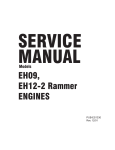
Parts List Symbols
• The star mark (*) means that the part is included in the kit set and is a genuine Yamaha
part. Therefore, you can easily purchase the part at any Yamaha part dealer when
necessary.
• The circle mark (°) means that when needed, the individual part is sold separately to the kit set.
No.
PART No.
˚
1
4C8-11181-70
*
2
5VY-11351-00
GASKET, CYLINDER 1
3
*
3
4C8-11603-00
PISTON RING SET
12
4
5VY-1165A-01
BOLT, CONNECTING ROD
SPECIAL
24
5
93450-18157
CIRCLIP
24
*
PART NAME
GASKET, CYLINDER
HEAD 1
Q’TY
3
REMARKS
t=0.30mm
Symbol Marks
Particularly important information is distinguished in this manual by the following notations.
This is the safety alert symbol. It is used to alert you to potential
personal injury hazards. Obey all safety messages that follow this
symbol to avoid possible injury or death.
WARNING
NOTICE
TIP
A WARNING indicates a hazardous situation which, if not avoided, could
result in death or serious injury.
A NOTICE indicates special precautions that must be taken to avoid
damage to the vehicle or other property.
A TIP provides key information to make procedures easier or clearer.
CONTENTS
1 Engine Specifications................................................................................... 1
2 Kit Parts ......................................................................................................... 2
2-1 Engine Parts.................................................................................................... 2
1.
2.
3.
4.
5.
6.
7.
8.
9.
10.
11.
12.
13.
14.
15.
16.
17.
18.
19.
20.
21.
22.
23.
Maintenance Set (2C0-MAINT-71) ....................................................................... 2
Spark Plug Set (5FL-R045Q-70, 13S-R373A-70)................................................. 3
Head Gasket ......................................................................................................... 4
Piston Set (13S-116A0-70) ................................................................................... 6
Connecting Rod Set (13S-1165B-70) ................................................................... 6
Crankshaft (2C0-11411-70) .................................................................................. 6
Cam Shaft and Cam Sprocket .............................................................................. 7
Valve Spring Set (2C0-A2110-70) ........................................................................ 8
Oil Pump (2C0-13300-70)..................................................................................... 8
Air Funnel Set (MGC-A300908-10)....................................................................... 9
Throttle Body Clamp Assembly (2CO-1351A-70) ............................................... 12
AIS Plug Set (13S-A4890-70) ............................................................................. 13
Clutch Spring Set (2CO-A6330-70) .................................................................... 15
Friction Plate Set (2CO-A6321-70) ..................................................................... 16
Slipper Clutch Setting Set (4B1-A6377-70) ........................................................ 17
Transmission Gear.............................................................................................. 20
Mission Maintenance Set (2C0-A7000-70) ......................................................... 24
Drive Sprocket .................................................................................................... 27
Sprocket Nut Set (2C0-A7463-70) ...................................................................... 28
ACM Set (2C0-F1400-71) ................................................................................... 29
Wire Harness Set (13S-F2590-71) ..................................................................... 30
ECU Set (2C0-8591A-91) ................................................................................... 35
Cable Interface (13S-8533A-70) ......................................................................... 36
2-2 Vehicle Accessories..................................................................................... 39
24.
25.
26.
27.
28.
29.
30.
31.
32.
33.
34.
35.
36.
Engine Protector Set (2C0-A5491-70) ................................................................ 39
Chassis Protector Set (2C0-C117G-70) ............................................................. 40
Oil Catch Tank Set (2C0-C1707-81)................................................................... 42
Rear Suspension ................................................................................................ 43
Rear Shock Spring.............................................................................................. 46
Front Fork ........................................................................................................... 47
Front Fork Spring ................................................................................................ 51
Steering Damper Stay Set (2C0-C3495-80) ....................................................... 57
Seat Cushion (13S-24713-70) ............................................................................ 58
Front Spare Wheel Assembly (2C0-25100-70)................................................... 59
Rear Spare Wheel Assembly (2C0-25300-70) ................................................... 60
Throttle Set (2C0-C6300-70) .............................................................................. 61
Throttle Set (13S-C6300-70)............................................................................... 62
3 Tightening Torque List ............................................................................... 63
4 YZF-R6 Wiring Diagram.............................................................................. 76
1 Engine Specifications
Spec
SSP
STK
STD
Displacement
599 cm³
599 cm³
599 cm³
Bore/Storke
67.0 x 42.5 mm
67.0 x 42.5 mm
67.0 x 42.5 mm
Maximum engine speed
(limiter controlled speed)
15800 rpm
15800 rpm
15800 rpm
14.5:1
(Depend of
head-gasket
thickness and
cylinder head
surface
grinding)
13.7:1
(Depending on
the thickness
of the head
gasket)
13.2:1
INT.
110°
105°
105°
EXT.
115°
110°
110°
0.60 mm
0.60 mm
0.70 mm
INT.
1.05 mm
(ATDC 12°)
1.05 mm
(ATDC 12°)
1.15 mm
(ATDC 12°)
EXT.
1.62 mm
(BTDC 12°)
1.62 mm
(BTDC 12°)
1.80 mm
(BTDC 12°)
INT.
0.15 – 0.19 mm
0.18 – 0.22 mm
0.18 – 0.22 mm
EXT.
0.23 – 0.27 mm
0.23 – 0.27 mm
0.23 – 0.27 mm
Compression ratio
(recommended value)
Valve timing (event angle)
Squish height (minimum)
Clearance between valve and
piston (minimum)
valve (tappet) clearance
–1–
2 Kit Parts
2-1 Engine Parts
1.
Maintenance Set (2C0-MAINT-71)
Parts List
No.
PART No.
PART NAME
Q'TY
°
1
2C0-11181-76
GASKET, CYLINDER HEAD
3
*
2
2C0-11603-00
PISTON RING SET
12
*
3
93450-16159
CIRCLIP
24
4
2C0-1165A-00
BOLT, CONNECTING ROD
24
*
5
90179-07001
NUT
24
*
6
4SV-12119-00
SEAL, VALVE STEM OIL
48
*
7
2C0-12213-00
GASKET, TENSIONER
3
°
8
2C0-13414-70
GASKET, STRAINER
3
ANTI STICK TYPE
°
9
2C0-15451-70
GASKET, CRANKCASE
COVER 1
3
ANTI STICK TYPE
°
10
2C0-15461-70
GASKET, CRANKCASE
COVER 2
3
ANTI STICK TYPE
°
11
2C0-15456-70
GSKT., 1
3
ANTI STICK TYPE
*
12
93102-35017
SEAL, OIL
3
FOR DRIVE AXLE
*
13
90151-06024
SCREW,
CROSSRECESSED
COUNTERSUNK
9
FOR BEARING
HOUSING
–2–
REMARKS
t=0.45mm
2.
Spark Plug Set (5FL-R045Q-70, 13S-R373A-70)
Parts List
Semi surface discharge Type (5FL-R045Q-70)
No.
PART No.
1
5FL-1119C-70
PART NAME
PLUG, SPARK
Q'TY
4
REMARKS
NGK R0045Q-10
Parts List
Angled ground strap Type (13S-R373A-70)
No.
PART No.
1
13S-1119C-70
PART NAME
PLUG, SPARK
Q'TY
4
REMARKS
NGK R0373A-10
TIP
Since these spark plugs have a copper gasket, caution is needed during installation on
the following points.
1. The tightening torque is 12 – 15 N•m (1.2 – 1.5 kgf•m).
2. When not checking the torque, tighten by rotating through 30° after manual
tightening in the case of new plugs. When reusing plugs, tighten by rotating through
15°.
–3–
3.
Head Gasket
Parts List
No.
PART No.
PART NAME
Q'TY
REMARKS
1
2C0-11181-71
GASKET, CYLINDER HEAD
1
t=0.40mm
2
2C0-11181-76
GASKET, CYLINDER HEAD
1
t=0.45mm
3
2C0-11181-81
GASKET, CYLINDER HEAD
1
t=0.50mm
4
2C0-11181-86
GASKET, CYLINDER HEAD
1
t=0.55mm
The thickness of the standard parts is 0.60mm.
These parts are used to adjust the squish height. In normal cases, use the one with -76
(0.45mm). After processing the cylinder (upper case), make sure to check the squish height
and use the gasket so that the squish height becomes 0.60mm or above.
TIP
Squish height means the gap between the flat portion of the piston and the head
cylinder.
Stamping location
–4–
Measuring the volume of the cylinder head combustion chamber
TIP
To obtain the highest performance for race use, the four cylinders should be uniform.
If you modify the head cylinder, always measure the combustion chamber volume and
do the work based on the measured value.
Measure the volume of the combustion chamber of the cylinder head (commonly called the
dome volume) as follows.
Measuring equipment
1. Burette
2. Glass plate
3. Oil (3:1 mixture of torque converter oil and white gasoline)
4. Vaseline (to seal the valve and glass plate)
Measurement method
1. Tighten a regulation spark plug to the regulation torque in the cylinder head to be
measured.
2. Set so that the alignment surface of the combustion chamber is level.
3. Apply a thin coat of Vaseline to the valve face and set the IN and EX valves.
4. Apply a thin coat of Vaseline to the combustion chamber alignment surface and set the
glass plate.
5. Add drops of oil from the burette. The total added amount minus the valve back clearance
is the volume of the combustion chamber.
–5–
4.
Piston Set (13S-116A0-70)
Parts List
No.
PART No.
PART NAME
Q'TY
*
1
13S-11631-00
PISTON
4
*
2
2C0-11603-00
PISTON RING SET
4
*
3
2C0-11633-00
PIN, PISTON
4
*
4
93450-16159
CIRCLIP
8
REMARKS
Select four pistons so that the difference in their weights does not exceed 0.5g.
5.
Connecting Rod Set (13S-1165B-70)
Parts List
*
No.
PART No.
1
13S-11650-00
PART NAME
CONN. ROD ASSY., 1
Q'TY
REMARKS
4
Select four connecting rod assemblies so that the difference in their weights does not exceed
2g and combine them so that the small end weights are uniform. (by Yamaha’s measuring method)
6.
Crankshaft (2C0-11411-70)
Parts List
*
No.
PART No.
1
2C0-11411-00
PART NAME
CRANKSHAFT
Select a crankshaft with good balance.
–6–
Q'TY
1
REMARKS
7.
Cam Shaft and Cam Sprocket
Parts List
No.
PART No.
PART NAME
Q'TY
REMARKS
1
2C0-12171-72
SHAFT, CAM 1
1
INT
2
2C0-12181-71
SHAFT, CAM 2
1
EXT
3
2C0-12176-80
SPROCKET, CAM 1
1
INT
4
2C0-12177-80
SPROCKET, CAM 2
1
EXT
Tightening torque
24 N•m (2.4 m•kg)
STD
Tightening torque
FWD.
Assembly of Cam Sprocket
By making the assembly holes of the cam sprocket of the racing kit long, the valve timing can
be adjusted within the range of -2º to +6 º (CA) compared with standard timing.
TIP
For valve timing adjustment, refer to the KIT TOOLS MANUAL.
NOTICE
• When fitting the camshaft, use the cam sprockets of the kit and always set the valve
timing to match. If otherwise, no intended performance can be expected and more
over, the engine may be damaged.
• When using this camshaft, use the valve spring set 2C0-A2110-70.
Sprocket assembly position at top dead center point of #1 cylinder compression
–7–
8.
Valve Spring Set (2C0-A2110-70)
Parts List
No.
PART No.
PART NAME
Q'TY
REMARKS
1
2C0-12113-70
SPRING,1
8
For 2C0-12171-71 (INT)
Identifying color:
Light blue
2
2C0-12114-70
SPRING,2
8
For 2C0-12181-71 (EXT)
Identifying color: Yellow
3
2C0-12117-70
RET., VALVE SPRING
16
• This set will be effective in improving the engine performance and durability if it is provided
exclusively for the kit cam shaft and used in combination.
NOTICE
When using this valve spring, use the camshafts 2C0-12171-71, 2C0-12171-72, and 2C012181-71.
9.
Oil Pump (2C0-13300-70)
Parts List
No.
PART No.
1
2C0-13300-70
PART NAME
OIL PUMP ASSY
Q'TY
1
• This pump is capable of a larger discharge than the STD counterpart.
–8–
REMARKS
10. Air Funnel Set (MGC-A300908-10)
Parts List
No.
PART No.
PART NAME
Q'TY
1
PRIMARY FUNNEL
2
2
SUPPORT L
1
3
SUPPORT R
1
4
EXTENSION FUNNEL R
2
5
EXTENSION FUNNEL L
2
REMARKS
L=15.9mm
• This set is capable of higher intake efficiency than the STD counterpart.
Fitting Method
1. Installing the Primary Funnel
Screw on the plates on the throttle body. Put only the 2 lower screw like on the schema. Use
standard screw.
2. Assemble Support and Axle
The axles are the standards ones; don’t forget to put the small ring into the hole.
*Use the lever and bushing intended for a STD machine.
Lever*
Bush*
Bush*
Support R
Support L
Lever assembly
–9–
3. Mount the Assembly
Secure the lever assembly to the primary funnel.
Secure using standard screws in the places illustrated.
Then put the screw on the superior part of the supports (shown by a red arrow on the photo
Below). Make sure that the axle can easily turn without friction.
4. Connecting Rod
Use standard connecting rod. Begin by clipping white prismatic side to the motor axle, then clip
other side to the tong of the inferior axle.
SHAFT ASSY.
A/C
LEVER ASSY.
Motor side
Lever side
PRIMARY FUNNEL
– 10 –
5. Fitting the Extention Funnel
Attach the extension funnel to the standard secondary funnel. Note the direction of the groove
on the extension funnel and connect with wire so that it does not turn and come off.
Secondary funnel
Extension funnel
Rubber seal
Wire
6. Fitting the Secondary Funnel
Fit the standard rubber seal to the secondary funnel before attaching the lever assembly.
Ycci System Control
You can use the Ycci system as the kit funnel.
You can control the operation timing by using the YMS software packed together with the kit
ECU.
You can also control the STD funnel by using the YMS software.
This set is made by MG Competition. For details of the specification, please check with MG
Competition.
TEL +33 (0) 4 50 25 59 96
FAX +33 (0) 4 50 25 59 98
Web http://www.mgcompetition.fr/
– 11 –
11. Throttle Body Clamp Assembly (2CO-1351A-70)
Parts List
No.
PART No.
1
2C0-1351A-70
PART NAME
Q'TY
THROTTLE BODY CLAMP
ASSY.
REMARKS
1
This part is used to enhance maintenance performance of the throttle body. Before using it, cut
off the protrusion for positioning bands at the cabjoint.
Cut it off
The part has a collar to prevent over-tightening. In normal cases, the part will not be tightened
till it reaches to the collar. Just manually tighten it.
Make sure to put a new band through a M4 x 0.7 tap before using it.
– 12 –
12. AIS Plug Set (13S-A4890-70)
This plug set is used when the AIS (Air Induction System), an exhaust gas purification system,
is removed.
Parts List
*
No.
PART No.
PART NAME
Q'TY
1
5SL-1482L-70
PLATE, 2
2
2
93608-16M16
PIN, DOWEL
4
3
90336-10020
PLUG, TAPER
1
REMARKS
Installation
1. Remove the hose attached to the cylinder head cover and the air cut-off valve assembly
accompanying the hose.
2. Remove the cap fitted to the hose and remove the reed valve and plate from the inside.
3. Install the plate (5SL-1482L-70) in replacement of the cap. Apply liquid gasket to the plate.
4. Remove the cylinder head cover and the four collars fitted to the cover. Install the PIN
(93608-16M16).
5. After removing the hose connected to the air cleaner case from the air-cut valve assembly,
open the upper case of the air cleaner case and insert the PLUG (90336-10020) into the
hole where the hose was connected.
– 13 –
STD
A/C ASSY.
REMOVE
KIT
Insertion
direction
A/C ASSY.
– 14 –
13. Clutch Spring Set (2CO-A6330-70)
Parts List
No.
PART No.
1
2C0-16334-70
PART NAME
SPRING, CLUTCH 2
Q'TY
6
REMARKS
Identifying color: Green
The clutch spring should have a bigger mounting load than standard.
– 15 –
14. Friction Plate Set (2CO-A6321-70)
Parts List
No.
PART No.
1
5EB-16321-72
PART NAME
PLATE, FRICTION 1
Q'TY
REMARKS
9
Compared to STD, the friction plate enhances durability and operation.
Identification Paint
(Violet)
– 16 –
15. Slipper Clutch Setting Set (4B1-A6377-70)
Parts List
No.
PART No.
1
4B1-16377-70
NUT, LOCK
1
2
4B1-16391-70
SHIM
3
a
PART NAME
2
Q’TY
REMARKS
1
c
b
42.4 – 43.0
– 17 –
(Setting of back torque limiter of clutch).
A clutch with a back torque limiter mechanism is installed in the YZF-R6 engines. The
operation of the back torque limiter can be adjusted through adjusting: 2 the number of SHIMs
(set up for the kit); a the number of springs; b the whole thickness of the clutch plate; and the
strength of c spring (set up for the kit) of the slipper clutch setting set.
(Recommended setting method)
To begin with, the dimensions of the clutch are re-set to the standard values. (For details,
please refer to the service manual published from YAMAHA MOTOR CO. LTD.
If you attach the slipper clutch setting of kit 1 2 , make it the same as the standard setting.
When decreasing the number of SHIMs (standard setting is three) of slipper clutch setting set,
the back torque limiter tends to be effective (Engine braking becomes less effective).
Standard
3
2
1
0
effective
(Engine braking becomes
less effective)
Further, when decreasing the number of a spring (the number of standard setting is three) to
two, the back torque limiter becomes effective (Engine braking becomes less effective).
The clutch spring c can be either the kit item or the standard item.
If you mount the clutch spring from the kit, the back torque limiter tends to be less effective (the
engine brake becomes stronger).
NOTICE
When decreasing the number of a spring to two, the caution should be taken to surely
use three pieces of SHIMs for the slipper clutch setting set. If its number being less than
the above, the less load may be supported so as to exert serious influences on driving.
Decreasing the number of a spring to one is not allowed.
– 18 –
3 a springs,
3 SHIMs
3 a springs,
2 SHIMs
3 a springs,
1 SHIM
Load
3 a springs,
0 SHIM
2 a springs,
3 SHIMs
As installed
In operation
Stroke
– 19 –
16. Transmission Gear
Parts List
No.
PART No.
1
2C0-17411-80-A
AXLE, MAIN
1
A
1
2C0-17411-90-B
AXLE, MAIN
1
B
*
1
2C0-17411-00
AXLE, MAIN
1
C
*
2
2C0-15163-00
HSG., BEARING
1
*
3
93306-20562
BRG.
1
4
2C0-17151-71-A
GEAR, 5TH PINION
1
A
4
2C0-17151-80-B
GEAR, 5TH PINION
1
B
4
2C0-17151-90-C
GEAR, 5TH PINION
1
C
5
2C0-17131-80-A
GEAR, 3RD PINION
1
A
5
2C0-17131-71-B
GEAR, 3RD PINION
1
B
5
2C0-17131-90-C
GEAR, 3RD PINION
1
C
6
2C0-17161-70-A
GEAR, 6TH PINION
1
A
6
2C0-17161-00
GEAR, 6TH PINION
1
B
6
2C0-17161-90-C
GEAR, 6TH PINION
1
C
7
2C0-17121-80-A
GEAR, 2ND PINION
1
A
7
2C0-17121-90-B
GEAR, 2ND PINION
1
B
7
2C0-17121-00
GEAR, 2ND PINION
1
C
8
2C0-17402-70
DRIVE, AXLE ASSY.
1
*
9
2C0-17421-00
AXLE, DRIVE
1
*
10
93305-20509
BRG.
1
*
11
90387-25016
COLLAR
1
12
2C0-17221-81-A
GEAR, 2ND WHEEL
1
A
12
2C0-17221-90-B
GEAR, 2ND WHEEL
1
B
12
2C0-17221-00
GEAR, 2ND WHEEL
1
C
13
2C0-17261-71-A
GEAR, 6TH WHEEL
1
A
13
2C0-17261-80-B
GEAR, 6TH WHEEL
1
B
13
2C0-17261-90-C
GEAR, 6TH WHEEL
1
C
14
2C0-17241-80-A
GEAR, 4TH WHEEL
1
A
14
2C0-17241-70-B
GEAR, 4TH WHEEL
1
B
14
2C0-17241-90-C
GEAR, 4TH WHEEL
1
C
15
2C0-17231-80-A
GEAR, 3RD WHEEL
1
A
15
2C0-17231-70-B
GEAR, 3RD WHEEL
1
B
15
2C0-17231-90-C
GEAR, 3RD WHEEL
1
C
16
2C0-17251-71-A
GEAR, 5TH WHEEL
1
A
16
2C0-17251-80-B
GEAR, 5TH WHEEL
1
B
16
2C0-17251-90-C
GEAR, 5TH WHEEL
1
C
17
2C0-17211-80-A
GEAR, 1ST WHEEL
1
A
17
2C0-17211-90-B
GEAR, 1ST WHEEL
1
B
*
*
*
PART NAME
– 20 –
Q'TY
REMARKS
Parts List
*
No.
PART No.
PART NAME
17
2C0-17211-00
Q'TY
GEAR, 1ST WHEEL
1
REMARKS
C
17
15
16
14
13
12
9
1
2
8
10
3
11
4
5
6
7
• Gear Ratio
std
A
B
C
1st
31/12 (2.583)
37/16 (2.313)
42/17 (2.471)
31/12 (2.583)
2nd
32/16 (2.000)
39/21 (1.857)
39/20 (1.950)
32/16 (2.000)
3rd
30/18 (1.667)
36/23 (1.565)
29/18 (1.611)
30/18 (1.667)
4th
26/18 (1.444)
25/18 (1.389)
26/18 (1.444)
28/19 (1.474)
5th
27/21 (1.286)
33/26 (1.269)
30/23 (1.304)
27/20 (1.350)
6th
23/20 (1.150)
25/22 (1.136)
23/20 (1.150)
26/22 (1.182)
NOTICE
• No gear can be used for the kit transmission except for the specified STD gear.
• There is no compatibility with the ’06 model transmission set (2C0-A7400-70).
– 21 –
YZF-R6 Mission ratio
Pinion gear
GEAR PLAN Ratio
1ST
2ND
3RD
4TH
5TH
6TH
Part number
Wheel gear
The Stamp
number
of teeth
Part number
The Stamp
number
of teeth
A
2.313 2C0-17411-80-A
16
A
2C0-17211-80-A
37
A
B
2.471 2C0-17411-90-B
17
B
2C0-17211-90-B
42
B
C
2.583
12
2C0-17211-00
31
A
1.857 2C0-17121-80-A
21
A
2C0-17221-81-A
39
A
B
1.950 2C0-17121-90-B
20
B
2C0-17221-90-B
39
B
C
2.000
16
2C0-17221-00
32
A
1.565 2C0-17131-80-A
23
A
2C0-17231-80-A
36
A
B
1.611 2C0-17131-71-B
18
B
2C0-17231-70-B
29
B
C
1.667 2C0-17131-90-C
18
C
2C0-17231-90-C
30
C
A
1.389 2C0-17131-80-A
18
A
2C0-17241-80-A
25
A
B
1.444 2C0-17131-71-B
18
B
2C0-17241-70-B
26
B
C
1.474 2C0-17131-90-C
19
C
2C0-17241-90-C
28
C
A
1.269 2C0-17151-71-A
26
A
2C0-17251-71-A
33
A
B
1.304 2C0-17151-80-B
23
B
2C0-17251-80-B
30
B
C
1.350 2C0-17151-90-C
20
C
2C0-17251-90-C
27
C
A
1.136 2C0-17161-70-A
22
A
2C0-17261-71-A
25
A
B
1.150
20
2C0-17261-80-B
23
B
C
1.182 2C0-17161-90-C
2C0-17261-90-C
26
C
2C0-17411-00
2C0-17121-00
2C0-17161-00
22
C
Make sure that the pinion and wheel gear are combined for use according to the chart plan.
– 22 –
YZF-R6 Speed List
Engine speed (rpm)
16000
Tire radius (mm)
315 perimeter (m) 1.979
Primary reduction ratio 41 85
2.073
GEAR
1st
2nd
3rd
– 23 –
4th
5th
6th
PLAN
The number
of teeth
16
16
16
16
15
16
15
16
15
16
15
14
16
15
14
15
14
15
14
15
14
14
14
14
45
46
47
48
45
49
46
50
47
51
48
45
52
49
46
50
47
51
48
52
49
50
51
52
Ratio
P
W
A
16
37
2.313
B
17
42
2.471
131.9 129.0 126.3 123.7 123.7 121.1 121.0 118.7 118.4 116.4 115.9 115.4 114.1 113.6 112.9 111.3 110.5 109.1 108.2 107.0 106.0 103.9 101.8 99.9
C
12
31
2.583
126.1 123.4 120.8 118.3 118.3 115.8 115.7 113.5 113.2 111.3 110.9 110.4 109.2 108.6 108.0 106.4 105.7 104.3 103.5 102.3 101.4 99.3
A
21
39
1.857
175.5 171.6 168.0 164.5 164.5 161.1 160.9 157.9 157.5 154.8 154.2 153.5 151.8 151.1 150.2 148.0 147.0 145.1 143.9 142.4 141.0 138.2 135.5 132.9
B
20
39
1.950
167.1 163.5 160.0 156.7 156.7 153.5 153.3 150.4 150.0 147.4 146.9 146.2 144.6 143.9 143.0 141.0 140.0 138.2 137.1 135.6 134.3 131.6 129.0 126.5
C
16
32
2.000
162.9 159.4 156.0 152.7 152.7 149.6 149.4 146.6 146.2 143.8 143.2 142.6 141.0 140.3 139.5 137.5 136.5 134.8 133.7 132.2 130.9 128.3 125.8 123.4
A
23
36
1.565
208.2 203.7 199.3 195.2 195.2 191.2 190.9 187.4 186.9 183.7 183.0 182.2 180.2 179.2 178.2 175.7 174.4 172.2 170.8 168.9 167.3 163.9 160.7 157.6
B
18
29
1.611
202.3 197.9 193.7 189.6 189.6 185.7 185.5 182.0 181.5 178.5 177.8 177.0 175.0 174.1 173.1 170.7 169.4 167.3 165.9 164.1 162.5 159.3 156.2 153.2
C
18
30
1.667
195.5 191.3 187.2 183.3 183.3 179.6 179.3 176.0 175.5 172.5 171.8 171.1 169.2 168.3 167.4 165.0 163.8 161.7 160.4 158.6 157.1 154.0 151.0 148.0
A
18
25
1.389
234.6 229.5 224.6 220.0 220.0 215.5 215.2 211.2 210.6 207.0 206.2 205.3 203.0 202.0 200.8 198.0 196.6 194.1 192.5 190.3 188.5 184.8 181.1 177.7
B
18
26
1.444
225.6 220.7 216.0 211.5 211.5 207.2 206.9 203.0 202.5 199.1 198.3 197.4 195.2 194.2 193.1 190.3 189.0 186.6 185.1 183.0 181.3 177.7 174.2 170.8
C
19
28
1.474
221.1 216.3 211.7 207.3 207.3 203.1 202.8 199.0 198.5 195.1 194.3 193.5 191.4 190.4 189.3 186.6 185.2 182.9 181.4 179.4 177.7 174.1 170.7 167.4
A
26
33
1.269
256.7 251.2 245.8 240.7 240.7 235.8 235.5 231.1 230.5 226.5 225.7 224.6 222.2 221.0 219.8 216.6 215.1 212.4 210.6 208.3 206.3 202.2 198.2 194.4
Engine Secondary
side
reduction
ratio
Wheel
(Sprocket)
side
140.9 137.9 134.9 132.1 132.1 129.4 129.2 126.8 126.5 124.3 123.8 123.3 121.9 121.3 120.6 118.9 118.1 116.6 115.6 114.3 113.2 111.0 108.8 106.7
97.4
95.5
B
23
30
1.304
249.8 244.4 239.2 234.2 234.2 229.4 229.1 224.8 224.2 220.4 219.6 218.6 216.2 215.1 213.8 210.8 209.3 206.7 204.9 202.7 200.8 196.7 192.9 189.2
C
20
27
1.350
241.4 236.1 231.1 226.3 226.3 221.7 221.4 217.2 216.7 213.0 212.1 211.2 208.9 207.8 206.6 203.7 202.2 199.7 198.0 195.8 194.0 190.1 186.4 182.8
A
22
25
1.136
286.8 280.5 274.6 268.8 268.8 263.3 263.0 258.1 257.4 253.0 252.0 250.9 248.2 246.9 245.5 242.0 240.2 237.2 235.2 232.6 230.4 225.8 221.4 217.1
B
20
23
1.150
283.4 277.2 271.3 265.6 265.6 260.2 259.9 255.0 254.3 250.0 249.0 247.9 245.2 244.0 242.5 239.1 237.4 234.4 232.4 229.9 227.7 223.1 218.8 214.6
C
22
26
1.182
275.7 269.7 264.0 258.5 258.5 253.2 252.9 248.2 247.5 243.3 242.3 241.3 238.6 237.4 236.0 232.6 231.0 228.1 226.2 223.7 221.6 217.1 212.9 208.8
• Values in the speed table may vary slightly according to tire manufacturer and size.
• Select after referring to the value in the speed table.
Speed
(km/h)
17. Mission Maintenance Set (2C0-A7000-70)
Parts List
No.
PART No.
PART NAME
*
21
90387-250R3
COLLAR
3
*
22
90209-21332
WASHER
6
*
23
93440-25186
CIRCLIP
10
*
24
90387-21003
COLLAR
3
*
25
90209-22352
WASHER
3
*
26
90209-21351
WASHER
3
*
27
90387-28011
COLLAR
3
*
28
90209-25011
WASHER
9
*
29
93440-28184
CIRCLIP
15
*
30
90387-25015
COLLAR
6
*
31
90214-25004
WASHER, CLAW
3
*
32
90214-25003
WASHER, CLAW
3
*
33
90387-21004
COLLAR
3
*
34
93102-35017
SEAL, OIL
3
*
35
93440-52014
CIRCLIP
5
*
36
90201-20278
WASHER, PLAIN
3
*
37
93306-20464
BRG.
3
*
38
93306-20464
BRG.
3
– 24 –
Q'TY
REMARKS
38
36
33
30
29
28
32
31
30
28
29
29
28
27
35
34
21
22
23
23
22
24
37
25
26
– 25 –
Transmission Assembly
The seal side should face outward (one side
seal bearing) and press in the bearing cup all
the way into the case until it touches bottom.
Apply molybdenum oil to inside of diameter.
After assembly, it should rotate smoothly.
Apply molybdenum oil to the inside diameter
and end. After assembly, it should rotate
smoothly.
Apply molybdenum oil to teeth of spline.
After assembly, it should slide smoothly.
Points to be careful of the oil seal assembly
The convex part on the oil seal should be
put into the case groove vertically so that
the oil seal does not fall over and is tightly
fit into the bearing cup of the bearing.
(Apply grease to the lip.)
TIP
• Always use a new circlip.
• Do not mistake the washer and circlip directions.
(See drawing below.)
Matching mark
Matching mark
Washer
Circlip
Washer
Gear
Washer
Shaft
Edge
Shaft
Edge
Detail of installation of washer
Position the abutment joint of the circlip
right between the splines.
Portion R
Rotate washer so that its teeth meet axlespline teeth on the axle, and then lock with
washer s claw.
Assemble washer with putting together
their matching mark.
Matching mark
Matching mark
Washer
Portion R
Detail of installation of circlip
Circlip
(Direction
not applicable)
Washer
Gear
Shaft
Washer
Edge
Portion R
Position the abutment joint of the
circlip right between the splines.
Shaft
Detail of installation of washer
Detail of installation of circlip
– 26 –
18. Drive Sprocket
Parts List
No.
PART No.
PART NAME
Q'TY
REMARKS
1
2C0-17460-74
SPROCKET, DRIVE
1
14T
2
2C0-17460-75
SPROCKET, DRIVE
1
15T
3
2C0-17460-76
SPROCKET, DRIVE
1
16T
These parts are for 520 chains (STD=525 chain).
Use the nuts for the kit to mount the drive sprocket.
These sprockets are manufactured to be compatible with new and old models.
GROOVE
MACHINING
STAMP OF THE NUMBER OF
TEETH ON BOTH SIDES
2CO ('06 and after YZF-R6)
5SL ('05 and previous YZF-R6)
Install with the grooved surface
facing outside of the chassis.
Install with the grooved surface
facing inside of the chassis.
NOTICE
Take care not to install the sprocket in the wrong direction. If it is installed in the wrong
direction, it will cause the misalignment of the drive and rear sprockets, leading to the
loss of power.
– 27 –
19. Sprocket Nut Set (2C0-A7463-70)
Parts List
*
No.
PART No.
PART NAME
1
90179-20005
NUT, SPROCKET
1
2
90215-21256
WASHER, TONGUED
1
TIGHTEN NUT BEFORE BENDING
– 28 –
Q'TY
REMARKS
20. ACM Set (2C0-F1400-71)
Parts List
No.
PART No.
1
2C0-81410-70
STATOR ASSY.
1
2
2C0-81450-70
ROTOR ASSY.
1
*
3
2C0-15580-00
STARTER CLUTCH OUT.
ASSY.
1
*
4
2C0-15536-00
CLIP, STARTER
1
5
2C0-15411-71
COVER, CRANKCASE 1
1
6
90149-06080
SCREW
3
With screw lock
7
2C0-15451-70
GSKT., CRANKCASE
COVER 1
1
ANTI STICK TYPE
*
PART NAME
Q'TY
REMARKS
TIP
Regarding Assembly
1. Remove grease from the taper surfaces of both rotor and crank before assembling
them.
2. Apply engine oil on the thread and flange of mounting bolts before using them.
STD
Tightening torque
70 N•m
Tightening torque
12.0 N•m
Tightening torque
– 29 –
21. Wire Harness Set (13S-F2590-71)
Parts List
No.
PART No.
1
13S-82590-71
WIRE HARNESS ASSY
1
2
5GF-83976-00
SW. HANDLE 1
1
PIT ROAD LIMITER
3
14B-83976-70
SW. HANDLE 1
1
MAP SELECT
4
2C0-2128A-70
BRKT.,REGULATOR 1
1
5
2C0-82509-70
WIRE SUB-LEAD
1
6
4C8-82188-70
RESISTOR ASSY.
1
*
7
90480-13003
GROMMET
2
*
8
90560-06201
SPACER
2
*
9
90111-06051
BOLT, HEX. SOCKET
BUTTON
4
*
10
92907-06200
WASHER, PLAIN
1
*
PART NAME
Q'TY
REMARKS
Linked to wire harness
NOTICE
• Do not remove the AC generator but leave it to function. Use on the battery alone will
make the machine unable to run in a short time.
• The wire harness will not function if it is not assembled with the ECU (2C0-8591A-90)
of the kit.
• The combination of this wire harness and ECU cannot be used with ’07 models.
• Map select switches Map 1 and Map 2 of the YMS “Comp. FUEL.”
NOTICE
When switching to Map 1 or Map 2 using “Map Select” while riding, check that proper
riding is possible even when using either map.
• You can use Map Select and Pit Road Limiter with the switches (2 types) included with this
set. (See diagram 1.)
(Diagram 1)
Main switch
Map select
1 → Map 1
2 → Map 2
Engine stop
switch
Pit road
limiter
Starter switch
– 30 –
• Use the 3-prong coupler in front with the red wire attached as the main switch. (See
diagram 2.)
Fitting it turns the power on and removing it turns the power off.
NOTICE
Be careful not to pull the wire too strongly.
(Diagram 2)
Main switch
• The switch installed to the STD machine may be used as is. (See diagram 3.)
(Diagram 3)
Main switch
Pit road limiter
Engine stop
switch
ON OFF
Not used
Map select
Lo → Map 1
Hi → Map 2
Starter switch
Pit road limiter
ON ↔ ON
PUSH=OFF
Ignition cut switch
– 31 –
• The ignition cut switch function can be used by combining the harness and kit ECU.
1 To use the STD switch (left side) to function as the ignition cut switch, connect the wire
sub-lead that was packaged with this set to the terminal that is normally connected to the
left side horn. (See diagram 4.) If you remove the resistor assy. at the tail side, the
ignition cut switch may malfunction in wet weather. (See diagram 5.)
NOTICE
Do not bend the resistor assembly. It will cease to function if it is bent.
2 Install the switch to the 2-pin black coupler underneath the fuel tank. Turning the switch
ON cuts the ignition.
(Diagram 4)
(Diagram 5)
5
6
NOTICE
Do not connect the coupler for resistor (black, 2-prong) and the coupler for power
(white, 2-prong). Connecting them may cause a malfunction. (See diagram 6.)
(Diagram 6)
Coupler for resistor
Coupler for power
– 32 –
• The bracket regulator provided with this set is for use when fitting a regulator in the position
illustrated in Diagram 7, such as when not using a standard radiator.
(Diagram 7)
9
8
4
7
10
D
FW
FRAME
RECTIFIER
REGULATOR
• This harness has a coupler that connects to the 2D made data logger. (See diagram 8.)
For details of the specifications of the data logger, please access the website.
Web http://www.2d-kit-system.com/
(Diagram 8)
Coupler
– 33 –
• This harness comes with a coupler (black 2-pole, plug) for use with a quick shifter.
(Connection diagram 74 E/G STP SW) (Diagram 9)
You can use any quick shifter product.
(Diagram 9)
Connector for steering damper
Connector for quick shifter
– 34 –
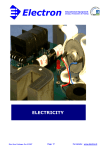
22. ECU Set (2C0-8591A-91)
Parts List
No.
PART No.
PART NAME
Q'TY
1
2C0-8591A-91
ECU
1
2
13S-2818Y-81
CD
1
REMARKS
YMS, MANUAL
• Use of this set and a wire harness included in the kit enables regulation (or setting) of fuel
injection and ignition timing, etc.
• For details as to how to regulate (or set) fuel injection and ignition timings, etc., refer to the
manual in the CD-ROM that comes with the set.
• There are two types of basic control data for the ECU included in this set: SS (Super
Sports) and ST (Stock Sports). They can be switched over and vice versa. To make it in the
ST specification, just remove two couplers located at the lower left of the kit harness fuel
tank. (See the figure below.)
<Setting-up Details>
SS specification: Kit cam shaft and *Recommended muffler
ST specification: *Recommended muffler
* Recommended muffler
Made by Akrapovic (For details of the specification, please access the website.)
Web http://www.akrapovic-exhaust.com/
MODEL
ECU
2006
2C0-8591A-70
2C0-82590-70
2007
2C0-8591A-71
2C0-82590-80
2008
2C0-8591A-80
2C0-8591A-90
2C0-8591A-91
13S-82590-70
13S-82590-71
2009
2010
WIRE HARNESS ASSY. THROTTLE BODY ASSY.
2C0-13750-00
13S-13750-00
*2008, 2009, and 2010 models allow any combination of ECU and wire harness. Other models
only allow the combinations shown in the table.
– 35 –
23. Cable Interface (13S-8533A-70)
Parts List
No.
PART No.
PART NAME
Q'TY
REMARKS
1
13S-8533A-70
CABLE, INTERFACE
1
USB
2
13S-N81CD-70
8cm CD
1
USB driver
• This cable connects the kit wire harness to the personal computer on which YEC FI
Matching System (YMS) is installed.
• Please see the YMS manual for instructions on how to use YMS.
• When connecting the cable to the PC for the first time, it is necessary to install the USB
driver. Refer to the USB Driver Installation Manual provided on the 8 cm CD for details on
how to install the USB driver.
• The product vendor ID and product ID are provided by the Hamamatsu TOA Electronics,
Inc.
Vendor ID: 6837
Product ID: 9001
– 36 –
• Use of the ECU in the kit and the harness allows functioning of the following codes in the
STD diagnosis.
* YMS-Monitor: YEC FI Matching System also allows functioning of the code shown below.
<Diagnosis Functions>
CODE
Contents
*YMS-Monitor
01
Throttle sensor
TPS 1(deg)
02
Atmospheric pressure sensor
Atmospheric (kPa)
03
Intake pressure sensor 1
Intake Air (kPa)
05
Intake temperature sensor
Air Temp. (°C)
06
Water temperature sensor
Water Temp. (°C)
07
Vehicle speed sensor
Speed Signal (--)
08
Overturn sensor
Lean Angle Signal
(V)
09
Monitor voltage
System Voltage (V)
13
Throttle sensor 2
TPS 2 (deg)
14
Accelerator sensor 1
APS 1 (deg)
15
Accelerator sensor 2
APS 2 (deg)
21
Neutral switch
Neutral SW
30
Ignition coil #1
—
31
Ignition coil #2
—
32
Ignition coil #3
—
33
Ignition coil #4
—
36
Injector (primary) #1
—
37
Injector (primary) #2
—
38
Injector (primary) #3
—
39
Injector (primary) #4
—
40
Injector (secondary) #1
—
41
Injector (secondary) #2
—
42
Injector (secondary) #3
—
43
Injector (secondary) #4
—
46
Intake funnel
—
50
Main relay
—
70
Program version
—
– 37 –
Self-Diagnosis Functions
• The ECU and harness in the kit provide the functions for the following codes of standard
self-diagnosis:
CODE
Description
00
All functions normally.
11
Cam angle sensor malfunctions.
12
Crank angle sensor malfunctions.
13
Intake pressure sensor malfunctions (open circuit / short circuit).
14
Intake pressure sensor malfunctions (piping system).
15
Throttle opening sensor malfunctions (open circuit / short circuit / ETV).
20
Intake pressure sensor or atmospheric pressure sensor malfunctions.
21
Water temperature sensor malfunctions (open circuit / short circuit).
22
Intake temperature sensor malfunctions (open circuit / short circuit).
23
Atmospheric pressure sensor malfunctions (open circuit / short circuit).
33
Ignition coil #1 malfunctions (open circuit).
34
Ignition coil #2 malfunctions (open circuit).
35
Ignition coil #3 malfunctions (open circuit).
36
Ignition coil #4 malfunctions (open circuit).
39
Injector (primary) malfunctions (open circuit).
40
Injector (secondary) malfunctions (open circuit).
43
Battery voltage monitor malfunctions (power source for fuel system).
46
Power source for vehicle malfunctions.
59
Accelerator opening sensor malfunctions (open circuit / short circuit).
60
Throttle motor malfunctions (drive system).
– 38 –
2-2 Vehicle Accessories
24. Engine Protector Set (2C0-A5491-70)
Parts List
No.
PART No.
PART NAME
Q'TY
1
2C0-15491-70
PROTECTOR
1
*
2
91314-06025
BOLT, HEX. SOCKET HEAD
2
*
3
91314-06020
BOLT, HEX. SOCKET HEAD
1
REMARKS
These parts protect the chassis as well as alleviating damage caused by overturning.
– 39 –
25. Chassis Protector Set (2C0-C117G-70)
Parts List
*
*
No.
PART No.
PART NAME
Q'TY
1
2C0-2117G-70
PROTECTOR(LH LONG)
1
2
2C0-2117G-90
PROTECTOR(RH SHORT)
1
3
2C0-21472-70
COLLAR, PROTECTOR
2
4
91317-10060
BOLT, HEX. SOCKET HEAD
1
5
91314-10065
BOLT, HEX. SOCKET HEAD
1
6
90201-10136
WASHER, PLAIN
2
REMARKS
Tightening torque
40 N•m (4.0 m•kg)
Tightening torque
40 N•m (4.0 m•kg)
ENGINE
FWD
Tightening torque
– 40 –
Before mounting the protector, cut the cowling so that the protector can fit against the chassis.
As a rough guide, cut by φ60 centered on the engine mount. See the figures below.
– 41 –
26. Oil Catch Tank Set (2C0-C1707-81)
Parts List
No.
PART No.
1
2C0-21707-70
OIL TANK COMP.
1
2
90450-25037
HOSE CLAMP ASSY.
4
3
13S-15373-70
PIPE, BREATHER
1
4
2C0-15393-70
PIPE, BREATHER 2
1
*
5
2C0-2419F-00
BRKT.
1
*
6
91317-06020
BOLT, HEX.SOCKET HEAD
2
*
7
90480-13018
GROMMET
2
*
8
90119-06044
BOLT, HEX. W/WASHER
2
9
2C0-15373-70
PIPE, BREATHER
1
*
PART NAME
Q'TY
REMARKS
For 2006 and 2007
models
This oil tank has the effective capacity of 540 cc.
6
OUT
A/C
5
8
IN
7
9
3
4
2
OUT
IN
1
545cc
For 2008 and 2009 models
For 2006 and 2007 models
– 42 –
27. Rear Suspension
Parts List
No.
PART No.
PART NAME
Q'TY
1
13S-22210-71
SHOCK ABSORBER, Rr.
1
REMARKS
98 N/mm
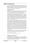
Rear Suspension Performance Adjustment Method
Low-speed compression damping, high-speed compression damping, rebound damping and
preload can be adjusted.
Low-speed
compression
damping adjustor
(bolt width 4mm,
hexagonal hole)
High-speed
compression
damping adjustor
(bolt width 12mm,
hexagonal)
Rebound damping
adjustor
Preload adjustor
Preload Adjustment Method
Turn the adjustor clockwise to increase the preload
and anticlockwise to reduce the preload.
The adjustment range is 8mm (in steps of 1mm)
Shipping position: Tightened 4 steps from the
preload minimum position (fifth
step)
– 43 –
Rebound Damping Adjustment Method
Turn clockwise to increase the damping force and
anticlockwise to reduce the damping force.
The adjustment range is between 3 to 20 steps back
from the lightly tightened adjustor position.
Shipping position: 15 steps back from the tightened
adjustor position
NOTICE
When tightening the adjustor, do it lightly. Over-tightening the adjustor can damage it.
Compression Damping Adjustment Method
At Low Speeds
Turn clockwise to increase the damping force and
anticlockwise to reduce the damping force.
The adjustment range is 1 to 20 steps back from the
lightly tightened adjustor position.
Shipping position: 15 steps back from the tightened
adjustor position
NOTICE
When tightening the adjustor, do it lightly. Over-tightening the adjustor can damage it.
At High Speeds
Turn clockwise to increase the damping force and
anticlockwise to reduce the damping force.
The adjustment range is 4 steps back from the lightly
tightened adjustor position.
Shipping position: 3 turns back from the tightened
adjustor position
NOTICE
When tightening the adjustor, do it lightly. Over-tightening the adjustor can damage it.
– 44 –
Performance and purpose of kit suspension (Differences compared with standard suspension on commercially available machines)
Spring characteristics
Purpose
To increase comfort when riding in urban areas while
preventing bottoming even with two people on the bike.
Performance/characteristics
Combination of springs and bump rubbers.
Problem with circuit
Easy to fully extend when braking. (high preload.)
Road-holding property of rear tire is easily lost during braking;
rear tire behavior (hopping, sliding, etc.) easily occurs.
Kit suspension specs
Commercially available machine
Spring load (N)
Commercially
available machine
specs
1G
Kit
Stroke (mm)
Addition of a rebound spring near full extension alleviates the above problem.
– 45 –
Commercially
available machine
specs
Purpose
To maintain comfort when riding in urban areas and improve
road-holding properties when banking into bends.
Performance/characteristics
Limits reaction force to the minimum required damping load.
Problem with circuit
Reduces machine stability. (excessive movement when
accelerating, passing over a gap, etc.)
Reduces turning performance (stroke volume is excessive
and the rear of the machine is lower than the front)
Kit suspension specs
Damping load (N)
Damping force characteristics
Commercially
available machine
Kit
Stroke speed (m/s)
Limits excessive dipping by increasing the damping force on the compression side.
Others
Kit suspension specs
Change in total length
Being assembled with a rebound spring, the kit suspension raises
the road-holding property of the rear tire when braking. (The total
length is changed according to the rebound spring setting.)
*Spring load: Depends on the stroke. Damping force: Depends on the stroke speed.
R1:293mm (STD:290mm)
R6:287mm (STD:290mm)
28. Rear Shock Spring
Parts List
•
•
•
•
•
No.
PART No.
PART NAME
Q'TY
REMARKS
1
13S-22222-70
SPRG., Rr. SHOCK
1
103 N/mm
Identifying stamp: 165-55103
2
13S-22222-75
SPRG., Rr. SHOCK
1
98 N/mm
Identifying stamp: 165-55-98
3
13S-22222-80
SPRG., Rr. SHOCK
1
93 N/mm
Identifying stamp: 165-55-93
These springs can be used with the standard or kit shock absorbers.
There is a stamp on the side of the springs for rate identification.
The stamp number indicates the length, diameter and rate.
For spring replacement, see the 13S STD. Service Manual.
The spring rate of the standard rear suspension is 103 N/mm.
– 46 –
29. Front Fork
Parts List
No.
PART No.
PART NAME
Q'TY
REMARKS
1
13S-23102-70
Fr. FORK ASSY. LH
1
9.5 N/mm
2
13S-23103-70
Fr. FORK ASSY. RH
1
9.5 N/mm
Front Fork Performance Adjustment Method
Compression low-speed damping, compression high-speed damping, rebound damping and
preload can be adjusted.
Preload Adjustment Method
Turn clockwise to increase the preload and
anticlockwise to reduce the preload.
The adjustment range is 15mm (1mm/turn)
Shipping position: Tightened 6 turns from
preload minimum position
the
Damping Adjustment Method
Turn clockwise to increase the damping force and anticlockwise to reduce the damping force.
The adjustment range is:
Rebound
: 1 to 25 steps back from the adjustor’s clockwise lightly tightened
position.
Compression low speeds : 1 to 20 steps back from the adjustor’s clockwise lightly tightened
position.
Compression high speeds: 4 turns back from the adjustor’s clockwise lightly tightened position.
Shipping position:
Rebound
: 20 steps back from the tightened adjustor position.
Compression low speeds : 10 steps back from the tightened adjustor position.
Compression high speeds: 2 turns back from the tightened adjustor position.
NOTICE
When tightening the adjustor, do it lightly. Over-tightening the adjustor can damage it.
– 47 –
Rebound damping adjustor
Compression low-speed
damping adjustor
– 48 –
Compression high-speed
damping adjustor
Performance and purpose of kit suspension (Differences compared with standard suspension on commercially available machines)
Commercially
available machine
specs
Purpose
Performance/characteristics
To increase comfort when riding in urban areas while
preventing bottoming when suddenly riding over a gap while
banking on a bend.
At the lowest possible spring setting, the air spring effect is
increased depending on the oil level.
An oil lock mechanism is fitted for the purpose of preventing
bottoming (metal contact).
Problem with circuit
Instability caused by excessive front dip movement during the
initial braking period.
– 49 –
Stroke cannot be used up. (Stroke stops sharply in the second
half of braking.)
Kit suspension specs
Linear spring characteristic can use up the entire range of the stroke while exerting the hold
of the initial braking period.
*Spring load: Depends on the stroke.
Spring load (N)
Spring characteristics
Kit
1G
Commercially
available machine
Stroke (mm)
Damping force characteristics
Purpose
To maintain comfort when riding in urban areas and improve
road-holding properties when banking into bends.
Performance/characteristics
Set the lowest possible damping force.
Problem with circuit
Instability caused by excessive front dip movement during the
initial braking period.
Reduces machine stability. (excessive movement when
accelerating, passing over a gap, etc.)
Kit suspension specs
By ensuring a damping force on the compression side, the kit enables the rider to change
the machine attitude gently and improves convergence when riding over a gap.
*Damping force: Depends on the stroke speed.
– 50 –
Others
Kit suspension specs
TiO coating inner tubes
adopted
Improves durability and lowers friction.
Spring support method
changed
Improves spring replacement operation. (Special tool
included.)
Bottoming rubber adopted
Improves gap absorbability during braking.
Damping load (N)
Commercially
available machine
specs
Commercially
available machine
Kit
Stroke speed (m/s)
30. Front Fork Spring
Parts List
No.
PART No.
PART NAME
Q'TY
REMARKS
1
13S-23151-70
SPRG., Fr. FORK
1
10.5 N/mm
Identifying slits 3
2
13S-23151-75
SPRG., Fr. FORK
1
10.0 N/mm
Identifying slits 2
3
13S-23151-80
SPRG., Fr. FORK
1
9.5 N/mm
Identifying slits None
4
13S-23151-85
SPRG., Fr. FORK
1
9.0 N/mm
Identifying slits 1
• There are slits at the ends of the spring for
rate identification.
• The number of slits indicates the rate as
shown above.
• When using an optional spring for the STD
fork, replace the supplied preload tube with
the set.
NOTICE
When using an optional spring for the kit fork, you do not need to replace the preload
tube. Use the original tube fitted to the fork.
TIP
• A spanner (SPECIAL TOOL) and rod (SPECIAL TOOL) are supplied with the front fork (13S23102-70).
• Use Yamaha M1 suspension oil.
– 51 –
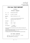
Front Fork Spring Replacement Method
1. Turn the damping adjustor and preload adjustor anticlockwise to set to the weakest
position.
2. After fixing the axle bracket in a vice, turn the fork bolt anticlockwise to lower the outer tube
until the dust seal touches the upper surface of the axle bracket.
Rebound damping adjustor
Preload adjustor
Fork bolt
Axle bracket
3. Insert the spanner (SPECIAL TOOL) into the notch of the spring seat upper and clamp the
14mm special nut.
4. Use a 14mm box spanner on the preload adjustor to remove the cap bolt assembly.
NOTICE
Do not remove the spanner (SPECIAL TOOL) while doing this.
Spanner
(SPECIAL TOOL)
Spring seat upper
Preload tube
– 52 –
5. Remove the push rod and fit the rod (SPECIAL TOOL) to the piston rod.
Push rod
Rod (SPECIAL TOOL)
6. Grip the rod (SPECIAL TOOL) firmly and remove the spanner (SPECIAL TOOL).
NOTICE
Be very careful to apply downward pressure on the rod (SPECIAL TOOL) when you remove
the spanner (SPECIAL TOOL).
– 53 –
7. Remove the spring seat upper and preload tube before removing the rod (SPECIAL TOOL).
8. Remove the washer, special nut and spring guide and replace the spring.
NOTICE
When replacing the spring, fit the new spring with the tapered closed end upwards.
Washer
Special nut
Spring guide
– 54 –
9. Press the rod downwards before adjusting the oil level.
• Oil level in load state: With the spring removed and the outer tube and rod lowered,
140mm from the top of the outer tube.
10. Reassemble the parts after oil level adjustment by following the disassembly procedure in
reverse.
Tightening torque: 20N/m
– 55 –
References
Front and rear load changes and front and rear suspension movement
in different scenarios.
Accelerating
. Load change
The wider the throttle is opened, the more the load
is concentrated on the rear.
. Front fork
Reaches nearly maximum extended stroke.
. Rear cushion
Up to 20 to 30mm stroke displacement, depending
on conditions.
Braking
. Load change
The harder the brake is applied, the more the load
is concentrated on the front.
. Front fork
Displaces until stroke has almost bottomed.
. Rear cushion
Reaches nearly maximum extended stroke.
Cornering
. Load change
Increases the load on the front fork and rear
cushion on both sides.
. Front fork
Up to 30 to 90mm stroke displacement depending
on the size of the corner.
. Rear cushion
Up to 25 to 40mm stroke displacement, depending on conditions.
– 56 –
31. Steering Damper Stay Set (2C0-C3495-80)
Parts List
No.
PART No.
1
2C0-23495-80
STAY, DAMPER
1
2
91317-06025
BOLT, HEX. SOCKET HEAD
1
3
2C0-23488-80
SPACER
1
4
91317-08110
BOLT, HEX. SOCKET HEAD
1
5
95607-08100
NUT, U
1
6
2C0-2349T-80
BRKT., DAMPER
1
*
7
90201-07081
WASHER, PLAIN
2
*
8
90149-06302
SCREW
2
9
5VY-26398-00
WASHER, SPECIAL
1
10
91317-08025
BOLT, HEX. SOCKET HEAD
1
11
2C0-23439-71
STOPPER, STRG. 2
1
12
90387-06084
COLLAR
1
*
13
90201-07081
WASHER, PLAIN
1
*
14
90149-06302
SCREW
1
15
2C0-23429-70
STOPPER
1
16
90151-04002
SCREW, CROSSRECESSED
COUNTERSUNK
2
*
*
*
*
PART NAME
Q'TY
For the steering damper, use [OHLINS SD121 STROKE 68mm].
– 57 –
REMARKS
32. Seat Cushion (13S-24713-70)
Parts List
No.
PART No.
1
13S-24713-70
PART NAME
CUSHION SEAT
Anti slip seat.
Cut to any size for use.
– 58 –
Q’TY
1
REMARKS
33. Front Spare Wheel Assembly (2C0-25100-70)
Parts List
*
No.
PART No.
PART NAME
Q'TY
1
2C0-25160-00
CAST WHEEL ASSY.
1
2
93900-00030
VALVE, RIM
1
REMARKS
*This kit does not include a tire.
This part is an assembly of bearings, spacers and an air valve in a STD wheel.
– 59 –
34. Rear Spare Wheel Assembly (2C0-25300-70)
Parts List
*
No.
PART No.
PART NAME
Q'TY
1
2C0-25370-00
CAST WHEEL ASSY.
1
2
93900-00030
VALVE, RIM
1
REMARKS
*This kit does not include a tire.
This part is an assembly of bearings, spacers and an air valve in a STD wheel.
– 60 –
35. Throttle Set (2C0-C6300-70)
Parts List
No.
PART No.
PART NAME
Q'TY
REMARKS
°
1
2C0-26281-70
CAP, GRIP UPPER
1
*
2
5FL-26282-00
CAP, GRIP UNDER
1
°
3
5SL-26243-71
TUBE, GUIDE
1
°
4
2C0-26391-70
CLIP, WIRE 1
1
°
5
2C0-26311-70
WIRE, THROTTLE 1
2
Grip side: Retracting
sharing
°
6
2C0-26313-70
WIRE, THROTTLE 3
2
Engine side: Retracting
sharing
°
7
2C0-26261-70
CYLINDER
2
°
8
5FL-26244-70
SLIDER
2
9
2C0-2639E-70
PROTECTOR
2
*
10
90201-261L1
WASHER, PLAIN
1
*
11
91314-05020
BOLT, HEX. SOCKET HEAD
2
*
12
91314-05008
BOLT, HEX. SOCKET HEAD
1
In this throttle set the throttle grip can be removed and maintained by itself.
12
4
5
10
7
8
9
6
3
1
2
11
Machining off the boss.
Scrape away CAP, GRIP UPPER
of the kit as shown above.
– 61 –
36. Throttle Set (13S-C6300-70)
Parts List
No.
PART No.
PART NAME
Q'TY
°
1
2C0-26281-70
CAP, GRIP UPPER
1
*
2
5FL-26282-00
CAP, GRIP UNDER
1
°
3
5SL-26243-71
TUBE, GUIDE
1
°
4
2C0-26391-70
CLIP, WIRE 1
1
°
5
13S-26302-70
THROTTLE WIRE ASSY.
2
*
6
90201-261L1
WASHER, PLAIN
1
*
7
91314-05020
BOLT, HEX. SOCKET HEAD
2
*
8
91314-05008
BOLT, HEX. SOCKET HEAD
1
REMARKS
Common use for pulling
back.
In this throttle set the working angle of the throttle grip turning is made smaller for quicker
response to the throttle openning.
&
"
#
$
!
%
Machining off the boss.
Scrape away CAP, GRIP UPPER
of the kit as shown above.
– 62 –
3 Tightening Torque List
Engine
To be tightened
Part No.
Part Name Screw dia.
x
pitch
Tightening
torque N•m
(kgf•m)
Q’ty
Remarks
CAP,
CAMSHAFT x
HEAD
90105-06027
BOLT,
FLANGE
M6 x 1.0
10.0±2 (1.0±0.2)
20
Embedded in
HEAD
95612-08625
BOLT,
STUD
M8 x 1.25
15.0±2 (1.5±0.2)
8
Tighten HEAD.
90179-10006
NUT
M10 x 1.25
TURN-OF-NUT
METHOD
AXIAL FORCE
41kN±2kN
SNUG TORQUE
28(2.8) +ROTATION ANGLE
55°
10
APPLY OIL
BOTH TO
THREAD AND
BEARING SURFACE. SEE
page 74 FOR
DETAILS.
Tighten HEAD.
90176-10075
NUT, CAP
M10 x 1.25
TURN-OF-NUT
METHOD
AXIAL FORCE
41kN±2kN
SNUG TORQUE
36(3.6) +ROTATION ANGLE
55°
2
APPLY OIL
BOTH TO
THREAD AND
BEARING SURFACE. SEE
page 74 FOR
DETAILS.
Tighten HEAD
on side of CAM
CHAIN
compartment.
90110-06094
BOLT,
HEXAGON
SOCKET
HEAD
M6 x 1.0
12.0±2 (1.2±0.2)
2
WITH WASHER
SPARK PLUG
5FL-1119C70
13S-1119C70
PLUG,
SPARK
M10S x 1.0
12 – 15
(1.2 – 1.5)
4
SEE page 3 FOR
DETAILS.
HEAD COVER x
HEAD
90109-066F0
BOLT
M6 x 1.0
12.0±2 (1.2±0.2)
6
Plug for sand
drain hole
90340-18002
PLUG,
STRAIGHT
SCREW
M18 x 1.5
42±4 (4.3±0.4)
3
Check bolt for oil
passage
95022-08012
BOLT,
FLANGE,
SMALL
HEAD
M8 x 1.25
15.0±2 (1.5±0.2)
1
Tighten AI CAP.
90110-06175
BOLT HEXAGON
SOCKET
HEAD
M6 x 1.0
10.0±2 (1.0±0.2)
4
CAMSHAFT x
SPROCKET
90105-07004
BOLT,
FLANGE
M7 x 1.0
24.0±2 (2.4±0.2)
4
JOINT,
CARBURETOR
1 x HEAD
91312-06016
BOLT,
HEXAGON
SOCKET
HEAD
M6 x 1.0
10.0±2 (1.0±0.2)
8
– 63 –
CAM SHAFT
SHALL TURN
LIGHTLY.
APPLY LOCKING AGENT
(LOCKTITE®).
Q’ty
Remarks
M7 x 0.75
8
APPLY MOLYBDENUM
DISULFIDE OIL
TO THREAD
BOLT,
CON ROD
M7 x 0.75
8
APPLY MOLYBDENUM
DISULFIDE OIL
TO THREAD
90179-07001
NUT
M7 x 0.75
14.7±1.47
(1.5±0.15)
+180°±5°
8
APPLY MOLYBDENUM
DISULFIDE OIL
TO BEARING
SURFACE
ACM ROTOR x
CRANKSHAFT
90105126A8
BOLT,
FLANGE
M12 x 1.25
70±5 (7.0±0.5)
1
DEGREASE
TAPERED SURFACE. APPLY
OIL BOTH TO
BOLT BEARING
SURFACE AND
THREAD AND
TO BOTH SIDES
OF WASHER.
USE MORICOATED
WASHER.
TENSIONER
ASSY x
CYLINDER
90110-06106
BOLT,
HEXAGON
SOCKET
HEAD
M6 x 1.0
12.0±2 (1.2±0.2)
2
INSTALL TENSIONER ASSY.
Install COVER,
THERMOSTAT.
91312-06020
BOLT,
HEXAGON
SOCKET
HEAD
M6 x 1.0
12.0±2 (1.2±0.2)
2
Install JOINT.
90105-06082
BOLT,
FLANGE,
SMALL
HEAD
M6 x 1.0
10.0±2 (1.0±0.2)
2
Install WATER
PUMP.
90110-06140
BOLT,
HEXAGON
SOCKET
HEAD
M6 x 1.0
12.0±2 (1.2±0.2)
2
OIL PUMP
ASSY x
CRANKCASE 2
95812-06030
BOLT,
FLANGE
M6 x 1.0
12.0±2 (1.2±0.2)
2
OIL PUMP
ASSY x
CRANKCASE 2
95812-06080
BOLT,
FLANGE
M6 x 1.0
12.0±2 (1.2±0.2)
1
COVER,
STRAINER x
CRANKCASE 2
90109-06015
BOLT
M6 x 1.0
12.0±2 (1.2±0.2)
13
To be tightened
Part No.
Part Name Screw dia.
x
pitch
CON ROD X
CAP, CON ROD
2C0-1165400
BOLT,
CON ROD
2C0-1165A00
– 64 –
Tightening
torque N•m
(kgf•m)
Tightening
torque N•m
(kgf•m)
Q’ty
M14 x 1.5
43.0±4 (4.3±0.4)
1
BOLT,
UNION
M20 x 1.5
70.0±5 (7.0±0.5)
1
5GH-1344020
OIL
CLEANER
ASSY
M20 x 1.5
17.0±2 (1.7±0.2)
1
HOLDER x
CRANKCASE 2
90110-06161
BOLT,
HEXAGON
SOCKET
HEAD
M6 x 1.0
12.0±2 (1.2±0.2)
2
PIPE, OIL x
CRANKCASE 2
90110-06161
BOLT,
HEXAGON
SOCKET
HEAD
M6 x 1.0
12.0±2 (1.2±0.2)
2
OIL COOLER x
CARNKCASE 2
5EB-1282200
BOLT,
UNION
M20 x 1.5
63.0±3 (6.3±0.3)
1
UPPER CASE x
CAP CASE
ASSY
92012-06020
BOLT,
BUTTON
HEAD
M6 x 1.0
5.0±0.5
(0.5±0.05)
4
UPPER CASE x
LOWER CASE
98902-05020
SCREW,
CROSS
RECESS
BINDING
M5 x 0.8
2.0±0.5
(0.2±0.05)
10
ELEMENT x
UPPER CASE
98902-05020
SCREW,
CROSS
RECESS
BINDING
M5 x 0.8
2.0±0.5
(0.2±0.05)
1
JOINT,
CARBURETOR
1 x THROTTLE
90450-56007
HOSE
CLAMP
ASSY
M5 x 0.8
2.0 – 2.5
(0.2 – 0.25)
4
THROTTLE x
FUNNEL
90109-05011
BOLT
M5 x 0.8
3.4 – 5
(0.34 – 0.5)
6
LOWER FILTER
CASE x
FUNNEL
(SUPPORT
UNIT)
90159-05035
SCREW,
WITH
WASHER
M5 x 0.8
2.5±0.5
(0.25±0.05)
2
Install
THROTTLE
WIRE
13S-2630200
THROTTLE WIRE
ASSY.
M6 x 1.0
3.5 – 5.5
(0.35 – 0.55)
2
To be tightened
Part No.
Part Name Screw dia.
x
pitch
DRAIN BOLT for
COVER,
STRAINER
90340-14132
PLUG,
STRAIGHT
SCREW
Tighten UNION
BOLT for
FILTER.
90401-20145
ELEMENT, OIL
FILTER
– 65 –
Remarks
DRAIN BOLT
APPLY GREASE
TO O-RING.
APPLY OIL TO
THREAD AND
BEARING SURFACE.
CONTACT-FIT
COLLAR OR
TORQUE CONTROL
To be tightened
Part No.
Part Name Screw dia.
x
pitch
Tightening
torque N•m
(kgf•m)
Q’ty
Remarks
NUT, RING x
HEAD
90179-08410
NUT
M8 x 1.25
20.0±2 (2.0±0.2)
8
TIGHTEN
EXHAUST PIPE
& HEAD.
STAY,
MUFFLER 1, 2 x
MUFFLER
91314-08035
BOLT,
HEXAGON
SOCKET
HEAD
M8 x 1.25
20.0±2 (2.0±0.2)
2
INSTALL
EXHAUST PIPE.
STAY,
MUFFLER 2 x
BRACKET,
MUFFLER 1
90105-08054
BOLT,
FLANGE
(SMALL
HEAD)
M8 x 1.25
34.0±4 (3.4±0.4)
1
INSTALL
DAMPER.
Tighten BAND,
MUFFLER.
91314-06030
BOLT,
HEXAGON
SOCKET
HEAD
M6 x 1.0
10.0±2 (1.0±0.2)
1
SILENCER x
FOOT REST
90105-08063
BOLT,
FLANGE
M8 x 1.25
20.0±2 (2.0±0.2)
1
Install WIRE
PULLEY.
13S-1133E00
13S-1133F00
WIRE,
PULLEY, 1
WIRE,
PULLEY, 2
M6 x 1.0
5 – 7 (0.5 – 0.7)
1
PULLEY x
GEARED
MOTOR
90110-05028
BOLT,
HEXAGON
SOCKET
HEAD
M5 x 0.8
6.5±1.5
(0.65±0.15)
1
BRACKET 7 x
FRAME
95827-06014
BOLT,
FLANGE
(SMALL
HEAD)
M6 x 1.0
6 – 10 (0.6 – 1.0)
2
BRACKET 7 x
SERVOMOTOR
95027-06025
BOLT,
FLANGE
(SMALL
HEAD)
M6 x 1.0
5 – 8 (0.5 – 0.8)
2
Install
MUFFLER
PROTECTOR.
90111-06071
BOLT,
HEXAGON
SOCKET
BUTTON
M6 x 1.0
8.0±1.5
(0.8±0.15)
1
Install
MUFFLER
PROTECTOR.
90111-06099
BOLT,
HEXAGON
SOCKET
BUTTON
M6 x 1.0
6.5±1.5
(0.65±0.15)
2
EXHAUST
VALVE
SUBASSY
90179-06063
NUT
M6 x 1.0
6.5±1.5
(0.65±0.15)
1
CRANKCASE 1
x CRANKCASE
2
90119-08083
BOLT,
HEXAGON
WITH
WASHER
M8 x 1.25
See page 75 for
details.
8
1
– 66 –
APPLY OIL
BOTH TO
THREAD AND
TO BEARING
SURFACE.
Tightening
torque N•m
(kgf•m)
Q’ty
M8 x 1.25
See page 75 for
details.
2
APPLY OIL
BOTH TO
THREAD AND
TO BEARING
SURFACE.
BOLT
M6 x 1.0
10.0±2 (1.0±0.2)
2
APPLY OIL
BOTH TO
THREAD AND
TO BEARING
SURFACE.
95812-06055
BOLT,
FLANGE
M6 x 1.0
10.0±2 (1.0±0.2)
7
APPLY OIL
BOTH TO
THREAD AND
TO BEARING
SURFACE.
CRANKCASE 1
x CRANKCASE
2
95812-08065
BOLT,
FLANGE
M8 x 1.25
24±2 (2.4±0.2)
2
APPLY OIL
BOTH TO
THREAD AND
TO BEARING
SURFACE.
CRANKCASE 1
x CRANKCASE
2
95812-06065
BOLT,
FLANGE
M6 x 1.0
10.0±2 (1.0±0.2)
3
APPLY OIL
BOTH TO
THREAD AND
TO BEARING
SURFACE.
CRANKCASE 1
x CRANKCASE
2
95812-06045
BOLT,
FLANGE
M6 x 1.0
10.0±2 (1.0±0.2)
3
APPLY OIL
BOTH TO
THREAD AND
TO BEARING
SURFACE.
CRANKCASE 1
x CRANKCASE
2
95812-06030
BOLT,
FLANGE
M6 x 1.0
10.0±2 (1.0±0.2)
1
APPLY OIL
BOTH TO
THREAD AND
TO BEARING
SURFACE.
Install COVER,
CRANKCASE 1.
90109-06015
BOLT
M6 x 1.0
12.0±2 (1.2±0.2)
9
Install COVER,
CRANKCASE 2.
90109-06031
BOLT
M6 x 1.0
12.0±2 (1.2±0.2)
7
Install COVER,
CRANKCASE 2.
90110-06156
BOLT,
HEXAGON
SOCKET
HEAD
M6 x 1.0
12.0±2 (1.2±0.2)
2
Install COVER
1.
90110-06303
BOLT,
HEXAGON
SOCKET
HEAD
M6 x 1.0
12.0±2 (1.2±0.2)
5
COVER 1 x
HOLDER,
CLUTCH
90109-06015
BOLT
M6 x 1.0
12.0±2 (1.2±0.2)
2
COVER 1 x
BOLT
92014-08014
BOLT,
BUTTON
HEAD
M8 x 1.25
15.0±2 (1.5±0.2)
1
To be tightened
Part No.
Part Name Screw dia.
x
pitch
CRANKCASE 1
x CRANKCASE
2
90119-08084
BOLT,
HEXAGON
WITH
WASHER
CRANKCASE 1
x CRANKCASE
2
90109-06100
CRANKCASE 1
x CRANKCASE
2
– 67 –
Remarks
To be tightened
Part No.
Part Name Screw dia.
x
pitch
Tightening
torque N•m
(kgf•m)
Q’ty
Remarks
COVER 1 x
PLUG,
STRAIGHT
90340-32004
PLUG,
STRAIGHT
SCREW
M32 x 1.5
CLOSE CONTACT WITH
BEARING SURFACE
1
PLATE,
BREATHER x C/
C1
90149-06082
SCREW
M6 x 1.0
12.0±2 (1.2±0.2)
3
COVER,
CRANKCASE 1
x STATOR
ASSY
90149-06080
SCREW
M6 x 1.0
10.0±2 (1.0±0.2)
3
PLUG WITH
COMMUNICATION
HOLE x
CRANKCASE 1
90149-06082
SCREW
M6 x 1.0
12.0±2 (1.2±0.2)
1
Install COVER,
CHAIN CASE.
90110-06060
BOLT,
HEXAGON
SOCKET
HEAD
M6 x 1.0
10.0±2 (1.0±0.2)
3
Install M
GALLERY
PLUG.
36Y-1518900
PLUG
M16 x 1.5
8.0±2 (0.8±0.2)
2
TAKE CARE
NOT TO OVERTIGHTEN
COVER,
CRANKCASE 1
x CLAMP
90149-06082
SCREW
M6 x 1.0
10.0±2 (1.0±0.2)
1
STATOR LEAD
Install COVER.
90109-06015
BOLT
M6 x 1.0
12.0±2 (1.2±0.2)
5
Install OIL PIPE
(OUTSIDE)
90110-06161
BOLT,
HEXAGON
SOCKET
HEAD
M6 x 1.0
12.0±2 (1.2±0.2)
2
CRANKCASE 2
x PICKUP
90110-06168
BOLT,
HEXAGON
SOCKET
HEAD
M6 x 1.0
10.0±2 (1.0±0.2)
2
Embedded in
CRANKCASE x
STUD,
EMBEDDED
90116-1002*
BOLT,
STUD
M10 x 1.25
(HEIGHT
68.2±1)
10
Install
PRESSURE
PLATE.
90159-06024
SCREW,
W/W
M6 x 1.0
8.0±2 (0.8±0.2)
6
BOSS, CLUTCH
x MAIN AXLE
4B1-1637770
NUT, LOCK
M20 x 1.0
115.0±5
(11.5±0.5)
1
– 68 –
CRIMP AND
APPLY OIL
BOTH TO
THREAD AND
BEARING SURFACE.
Tightening
torque N•m
(kgf•m)
Q’ty
M8 x 1.25
25.0±2 (2.5±0.2)
6
NUT
M20 x 1.0
85.0±5 (8.5±0.5)
1
WITH LOCK
WASHER
90151-06024
SCREW,
CROSSRECESSED
COUNTERSUNK
M6 x 1.0
12.0±2 (1.2±0.2)
3
CRIMP.
Install
STOPPER,
SHAFT BAR.
90110-06182
BOLT,
HEXAGON
M6 x 1.0
10.0±2 (1.0±0.2)
2
STOPPER
embedded in
CRANKCASE
1D7-1812700
STOPPER,
SCREW
M8 x 1.25
22.0±2 (2.2±0.2)
1
Install ARM,
SHIFT.
95822-06020
BOLT,
FLANGE
M6 x 1.0
10.0±2 (1.0±0.2)
1
Install ROTOR,
PICKUP.
90105-08113
BOLT,
FLANGE
M8 x 1.25
35.0±5 (3.5±0.5)
1
Install
STARTER
MOTOR.
90105-06083
BOLT,
FLANGE
(SMALL
HEAD)
M6 x 1.0
10.0±2 (1.0±0.2)
2
NEUTRAL
SWITCH ASSY
3GB-8254001
NEUTRAL
S/W ASSY
M10 x 1.25
19.6±2 (2.0±0.2)
1
OVERTIGHTENING LEADS TO
DAMAGE.
Install OIL
LEVEL
SENSOR.
95022-06016
BOLT,
FLANGE
(SMALL
HEAD)
M6 x 1.0
10.0±2 (1.0±0.2)
2
APPLY GREASE
TO O-RING.
SPEED
SENSOR x C/C
91312-06016
BOLT,
HEXAGON
SOCKET
HEAD
M6 x 1.0
10.0±2 (1.0±0.2)
1
CAM SENSOR x
COVER H/C
90110-06175
BOLT,
HEXAGON
SOCKET
HEAD
M6 x 1.0
7.5±1.5
(0.75±0.15)
1
WIRE
HARNESS
(NEGATIVE
LEAD WIRE)
91380-06012
BOLT,
HEXAGON
SOCKET
HEAD
M6 x 1.0
10.0±2 (1.0±0.2)
1
To be tightened
Part No.
Part Name Screw dia.
x
pitch
BOSS,
PRESSURE
PLATE x BOLT,
STUD
2C0-1637400
BOLT,
STUD
Install
SPROCKET,
DRIVE.
90179-20005
HOUSING,
BEARING
– 69 –
Remarks
CHECK FOR
SERRATION
TIGHTENING
UP.
To be tightened
Part No.
Part Name Screw dia.
x
pitch
Tightening
torque N•m
(kgf•m)
Q’ty
Install O2
SENSOR.
13S-8592A00
O2 SENSOR
M18 x 1.5
45.0±5 (4.5±0.5)
1
Install
THERMOSENSOR.
8CC-8579001
THERMOSENSOR
ASSY
M12 x 1.5
17.6±2 (1.8±0.2)
1
– 70 –
Remarks
Body
To be tightened
Part No.
Part Name Screw dia.
x
pitch
Tightening
torque N•m
(kgf•m)
Q’ty
HANDLE,
CROWN &
OUTER TUBE
91314-08030
BOLT,
HEXAGON
SOCKET
HEAD
M8 x 1.25
23 – 28
(2.3 – 2.8)
2
HANDLE,
CROWN &
STEERING
SHAFT
90170-28419
NUT, HEXAGON
M28 x 1.0
100 – 125
(10.2 – 12.7)
1
HANDLE &
OUTER TUBE
91314-08030
BOLT,
HEXAGON
SOCKET
HEAD
M8 x 1.25
28 – 35
(2.8 – 3.6)
2
STEERING
SHAFT and
RING NUT
90179-30691
NUT
M30 x 1.0
12 – 15
(1.2 – 1.5)
1
OUTER TUBE &
UNDER
BRACKET
91314-08030
BOLT,
HEXAGON
SOCKET
HEAD
M8 x 1.25
20 – 25
(2.0 – 2.5)
4
E/G BRACKET,
FRONT
95024-10040
BOLT,
FLANGE
(SMALL
HEAD)
M10 x 1.25
35 – 45
(3.6 – 4.6)
2
E/G BRACKET,
REAR UPPER
90105-12228
BOLT,
FLANGE
M12 x 1.25
90179-12248
NUT
M12 x 1.25
90105-12228
BOLT,
FLANGE
M12 x 1.25
90179-12248
NUT
M12 x 1.25
58 – 70
(5.9 – 7.1)
1
MAIN FRAME &
REAR FRAME
90149-10002
SCREW
M10 x 1.25
33 – 40
(3.3 – 4.1)
4
PIVOT SHAFT &
FRAME
2C0-2214110
SHAFT,
PIVOT
M32 x 1.5
12 – 19
(12.2 – 1.9)
1
ARM, RELAY 1
& FRAME
90109-10017
BOLT
M10 x 1.25
95602-10200
NUT, U
FLANGE
M10 x 1.25
90109-12010
BOLT
M12 x 1.25
90185-12119
NUT, SELF
LOCKING
M12 x 1.25
E/G BRACKET,
REAR UNDER
ARM, RELAY 1
& ARM 1
– 71 –
Remarks
1
58 – 70
(5.9 – 7.1)
1
1
1
31 – 49
(3.2 – 5)
1
1
31 – 49
(3.2 – 5)
SCREW IN
FROM THE
LEFT SIDE
1
SCREW IN
FROM THE
LEFT SIDE
Part Name Screw dia.
x
pitch
Tightening
torque N•m
(kgf•m)
Q’ty
Remarks
To be tightened
Part No.
ARM 1 & REAR
ARM
90109-12010
BOLT
M12 x 1.25
90185-12119
NUT, SELF
LOCKING
M12 x 1.25
REAR
CUSHION &
ARM, RELAY 1
90109-12011
BOLT
M12 x 1.25
90185-12119
NUT, SELF
LOCKING
M12 x 1.25
31 – 49
(3.2 – 5)
1
CHAIN PULLER
ADJUST NUT
95604-08200
NUT, U
FLANGE
M8 x 1.25
12 – 19
(12.2 – 1.9)
2
SHAFT, PIVOT
& LOCK NUT
2C0-2225200
NUT 2
M32 x 1.5
75 – 115
(7.6 – 11.7)
1
SHAFT, PIVOT
& U NUT
90185-22002
NUT SELF
LOCKING
M22 x 1.5
55 – 85
(5.6 – 8.7)
1
FUEL PUMP &
FUEL TANK
90110-05028
BOLT,
HEXAGON
SOCKET
HEAD
M5 x 0.8
3–5
(0.3 – 0.5)
6
FRONT STAY
for FUEL TANK
& FRAME
90110-06233
BOLT,
HEXAGON
SOCKET
HEAD
M6 x 1.0
5–8
(0.5 – 0.8)
1
Mid portion of
FUEL TANK &
STAY
91312-06016
BOLT,
HEXAGON
SOCKET
HEAD
M6 x 1.0
7 – 10
(0.7 – 1.0)
2
BRACKET,
TANK (rear) &
FUEL TANK
91312-06090
BOLT,
HEXAGON
SOCKET
HEAD
M6 x 1.0
5–8
(0.5 – 0.8)
1
BRACKET,
TANK (rear) &
REAR FRAME
90111-06071
BOLT,
HEXAGON
SOCKET
BUTTON
M6 x 1.0
5–8
(0.5 – 0.8)
4
FRONT WHEEL
SHAFT & FR
FORK
90105-14002
BOLT,
FLANGE
M14 x 1.5
REAR WHEEL
SHAFT & NUT
90185-24007
NUT, SELF
LOCKING
M24 x 1.5
90 – 130
(9.2 – 13.3)
1
FR CALIPER &
FR FORK
90401-10012
BOLT,
UNION
M10 x 1.25
30 – 40
(3.1 – 4.1)
4
DISC BRAKE &
FR WHEEL
90149-06043
SCREW
M6 x 1.0
14 – 22
(1.4 – 2.2)
10
APPLY LOCKING AGENT
(LOCKTITE®).
DISC BRAKE &
RR WHEEL
90149-08009
SCREW
M8 x 1.25
23 – 37
(2.3 – 3.8)
5
APPLY LOCKING AGENT
(LOCKTITE®).
– 72 –
1
31 – 49
(3.2 – 5)
SCREW IN
FROM THE
LEFT SIDE
1
1
SCREW IN
FROM THE
LEFT SIDE
1
To be tightened
Part No.
Part Name Screw dia.
x
pitch
Tightening
torque N•m
(kgf•m)
Q’ty
REAR WHEEL
SPROCKET &
CLUTCH HUB
90185-10009
NUT, SELF
LOCKING
M10 x 1.25
90 – 109
(9.2 – 11.1)
6
SPLIT BOLT for
FRONT AXLE
91314-08040
BOLT,
HEXAGON
SOCKET
HEAD
M8 x 1.25
18 – 23
(1.8 – 2.3)
4
– 73 –
Remarks
Tightening the Cylinder Head
Tightening the Cylinder Head (Turn-of-Nut Method)
1. Tighten the bolts in the tightening sequence of 1 to 7 to a snug torque of 28N•m (2.8kgf•m).
2. Tighten the bolts in the tightening sequence of 8 and 9 to a snug torque of 36N•m
(3.6kgf•m).
3. Tighten the bolt in the tightening sequence of 10 to a snug torque of 28N•m (2.8kgf•m).
4. Retighten the bolts in the tightening sequence of 1 to 10 to a turn-of-nut angle of 55°.
TIP
The numbers 1 to 10 show the sequence in which the bolts are tightened.
Apply engine oil to the bolt threads, contact surfaces, and washers.
These numbers indicate the tightening sequence.
– 74 –
Installing the Crankcase
Tightening the bolts
1. Tighten the bolts in the tightening sequence of 1 to 10 to 20N•m (2.0kg•m).
2. After loosening the bolts once in the tightening sequence of 1 to 10, retighten them one by
one to 12N•m (1.2kg•m).
3. Retighten the bolts in the tightening sequence of 1 to 7 to a turn-of-nut angle of 50°±5°.
4. Retighten the bolts in the tightening sequence of 8 and 9 to a turn-of-nut angle of 75°±5°.
5. Retighten the bolt in the sequence of 10 to a turn-of-nut angle of 50°±5°.
6. Tighten the bolts in the tightening sequence of 11 and 12 to 24±2N•m (2.4±0.2kgf•m).
7. Tighten the bolts in the tightening sequence of 13 to 29 to 10±2N•m (1.0±0.2kgf•m).
TIP
The numbers 1 to 29 show the sequence in which the bolts are tightened.
Apply engine oil to the bolt threads and both sides of the washers.
These numbers indicate the tightening sequence.
– 75 –
4 YZF-R6 Wiring Diagram
G
WL BrY RL
SbW BrB -
D
C
GB RB RL
LB BL OrB
PW L -
RL RB GB
OrB BL LB
- L PW
RL BrY WL
- BrB SbW
(BLACK)
MAIN HARNESS WIRE SUB LEAD 3
16
R
B
W
W
7.5A
(BLACK)
WIRE SUB LEAD 2
(BLACK)
MAIN HARNESS
WIRE SUB LEAD 1
RW2
R
W
RB C RB
RB
WWW
(BLACK)
MAIN HARNESS
GyR Or RB OrG
WB - L GyG
BL - - -
OrG RB Or GyR
GyG L - WB
- - - BL
(BLACK)
WWW
W W
W W
W W
R
50A
R
15
B RB
R3
77
RB
WL2 PW L3 W - WB RW
SbW2 G WR Gy - L L2 - BrW - G2
GW WR2 P YL BL Y BL2
YR LB2 B2 BY - Or GyR OrG GyG
LgR Lg LW RB GB LB OrB B4
RW2 YG LY WL SbW BrY BrB B3
R2 YB1 WY - - - - RL B
Or C Or
Or RB
Or
(BLACK)
7
11
B
B
3
RL
LY
R2
RW
YL
R2
R3
R3
R
R3
RB B
1
R
VM
MR
VB
MS
LAN
IG1
Or
IG2
GyR
RB
GyR C GyR
GyR RB
GyR
(BLACK)
IT
R R2
RW LW
RB
R
LW
W
WR
BL2
LW
Y
G2
GW B
RW
BL2
L3
AP1
60
29
6189-0933
BL2 L3 L2 G
RL B
(BLACK)
L2
L2
L3
G
YB1
BY
LB2
B
B
6189-0934(Dg)
RL RB
FWE
RST
RXD
TXD
FWE2
RST2
IJ11
RB RB D RB
(GRAY)
IJ12
GB GB D GB
(GRAY)
31
RB
RL
RL GB
G
TP2
15A
Y
G2
GW
RL
Br
(BLACK)
14
L
TP1
Br
GyG RB
GyG
WR
(BLACK)
R Br
18
R
RL
LY
RW
- RW2
RW
RB
GyG C GyG
GyG
IG4
BL W L WR
79
(BLACK)
13
BL
W
59
- RB - RL
- LW3 LY RW - - - - -
AP2
R
-
9
B
5
OrG RB
OrG
RL
RL
78
(BLACK)
OrG C OrG
OrG
IG3
G
G2 R
Y B
R
73
RB
LW3
2
ST
84
AP1
AP2
SGND2
D
B
RW
RL
RL
15A
12
4
32
GB
RL
RL LB
VCC2
TP1
TP2
TC
NL
SS
(GRAY)
LB LB D LB
IJ13
33
LB
RL
RL OrB
IJ14
OrBOrB D OrB
(GRAY)OrB
IJ21
WL WL G WL
(GRAY) WL
34
RL
RW LW GY
Br B RB
START
E/G STOP
25
OFF
RUN
(BLUE) (BLUE)
FREE
PUSH
82
LB2
B
30
(BLACK)
(BLACK)
YB1 Y
WY GW
Y YB
GW WY
(BLACK)
(BLACK)
RL WL
RW
Y
GW
YB1
WY
B
POWER
TPS
76
W/TEMP
TACHO
SPEED
GND
FUEL
BL Gy
B Gy
BY
NEUTRAL
67
BL
86
(GRAY) SbW
IJ22
SbW SbW G SbW
Gy
CRK
BL
SGND1
IJ23
BrY BrY G BrY
36
RL
L
WB
VCC1
CAM
RL BrY
(GRAY) BrY
37
RL
RL BrB
BrW
BrB BrB G BrB
IJ24
BY
B
Br
Y
RL
OH
65
OIL
RW
35
RL SbW
Gy
B
187
187
Br
Y
B
- LW RW
RB B -
LB2
24
B RW
BL
LW
RW
RB
O2
RW B
(GRAY) BrB
38
RL
TACHO
SHIFT
BrW
Brw BL
AT
VTHM
RW2
THMTHM+
LgR
YR
B
(BLACK)
BL
GW
GW BL
TURN L
B
B
B
WR2
TURN R
C
L
L
WB C WB
BL C BL
YG
L
BL
COLOR CORD
R B
WR B
WR2 B
(BLACK)
(BLACK)
L WY
BL
GND
CONNECTOR MARK (BETWEEN MAIN & SUB HARNESS)
CONNECTOR SYMBOL
– 76 –
SbW2 WL2
74
72
CONNECTING WITH GND.WIRE
A, B, C,
WR2
83
OrR
P
BW
- - L YG BL
EXP
HLR
RFR
PA
FD
SP
WL2
SBw2
85
(BLACK)
64
WL2
SbW2
PGND CGND
P/GND CGND
W LY
BL
(BLACK)
RW
R,Br,BrW,
EXPLANATION
L
WB
BL
71
L WB
BL
81
P
YG
WY
6189-0970
ILLUMINATION
R RW BW - - YL BR YB1
RW - - GW - - - -
MARK
70
BL P L
(DARK BLUE)
RY BrW WY Y Dg
Br - B - Ch
B B - LB2 BY
B - WR2 - L
L
BL
P
EXM+
EXM-
WR2
OFF
ON
Lg
C
BW
P OrR
BW
L
HI
LO
R
N
L
PB
470
HORN
PW
6189-0970
B
OFF
ON
DIMMER
AI
B4
B3
B2
B
ON
OFF
PASS.
HI BEAM
L
WY
BL
HAZARD
54
TURN
(BLACK)
(DARK GREEN)
AMP 1-174374-4
(DARK BLUE)
BR
YR LgR
WT
Lg
69
BL PW L
TEMP
W
80
L L D L
BL BL D BL
PW PW D PW
LgR
YR
75
B B
WR2 L
(BLACK)
(BLACK)
B B
B
BR
LB2
L
BY
EG
61
GW
YB1
YL
WR2
R
BR
GW
68
Lg B
No.
1
2
3
4
5
6
7
8
9
10
11
12
13
14
15
16
17
18
19
20
21
22
23
24
25
26
27
28
29
30
31
32
33
34
35
36
37
38
39
40
41
42
43
44
45
46
47
48
49
50
51
52
53
54
55
56
57
58
59
60
61
62
63
64
65
66
67
68
69
70
71
72
73
74
75
76
77
78
79
80
81
82
83
84
85
86
COMPONENTS
BTRY.
WIRE MINUS LEAD
ACM
STARTER RELAY
STARTER MOTOR
REC/REGU
RELAY ASSY
IG.COIL 1
IG.COIL 2
IG.COIL 3
IG.COIL 4
MAIN FUSE
FUSE(ETV)
FUSE(IGNITION)
SW.HANDLE R
FR.STOP SW.
FUEL PUMP
METER
INJECTOR 11
INJECTOR 12
INJECTOR 13
INJECTOR 14
INJECTOR 21
INJECTOR 22
INJECTOR 23
INJECTOR 24
OIL LEVEL GAUGE
APS
TPS
THROTTLE MOTOR
SENSOR,LEAN ANGLE
CRANK SHAFT SENSOR
AIR TEMP SENSOR
WATER TEMP SENSOR
PRESSURE SENSOR(Pb)
PRESSURE SENSOR(Pa)
CAM SHAFT SENSOR
SPEED SENSOR
E/G EARTH
E/G STOP SW.
SELECT SW.
MEASUREMENT TOOL
POWER SUPPLY
P/C I/F
MAIN SW.
SW.HANDLE
SUB-LD
PIT ROAD LIMIT SW.
VI MOTOR
ECU
RESISTOR ASSY.
MAP SELECT SW.
Published by YAMAHA MOTOR ENGINEERING co., LTD