1
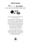
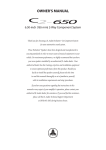
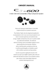
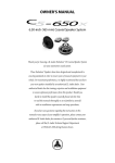
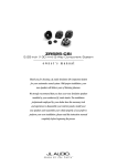
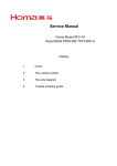
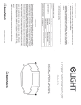
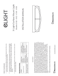
GRP, TP Motor Voltage Change
This procedure will provide you with step by step instructions to
convert 208/230 V operating voltage to 460V in dual voltage motors.
You Need:
5mm Allen Wrench
Wire Cutters
Wire Strippers
Terminal Crimp Tool
Qty 6-Crimpable Wire Nut
Hoist or Qty 2-2x4s
1. Remove pump from service. Disconnect
power supply. Clean and decontaminate
pump prior to working on it. See the
pump Installation, Operation, and
Maintenance Manual for detailed
instructions.
2. With pump in stable, upright position,
remove the 5mm cap screws as
indicated.
Publication
88FN2045A
3. Carefully lift stator housing 3 inches with
hoist, if available, and check under stator
housing for internal seal probe.
CAREFUL: lifting housing more than 3
inches may damage seal probe. If no
hoist is available, lift by hand and slide
the 2x4s under the housing to hold it up.
Disconnect probe if installed. Carefully lift
stator housing off the pump.
Please Contact Technical Support At 203-736-8890 With Any Additional Questions
Please Be Prepared To Provide Pump Serial Number During Call
Page
1 of 5
4. Sometimes the housing will be difficult to
remove. Twist the housing ¼ turn (90
degrees), exposing the bottom of the
cable entry horn. Using a soft faced
hammer, gently tap the cable entry horn
to free the stator housing.
6. With motor disassembled, turn stator
housing upside down, and support it so it
is free standing. Stator windings and
cable leads must be visible and easy to
reach. Your unit should now look like
this. Gently remove all wires from around
the stator windings. Take care not to
damage the winding insulation. Do not
use sharp tools!!
5. With stator housing removed, determine if
a wavy washer is present by checking the
top of the bearing, the top of the stator
housing, and the stator windings. Place it
aside until reassembly.
Publication
88FN2045A
Please Contact Technical Support At 203-736-8890 With Any Additional Questions
Please Be Prepared To Provide Pump Serial Number During Call
Page
2 of 5
Note: Refer to markers on the end of the
cable to identify L1, L2, and L3. If markers
are missing, consult HOMA document
number 88WA3005A-“Missing Wire Numbers
ID” available online.
Note: Wiring may be color coded or
numbered. See below for wire Identification.
7. Separate the wire bundles as indicated,
and record the wire numbers in each
bundle.
The pump will have 4 wire bundles.
Bundle 1 ___
___
___
Bundle 2 ___
___
___
Bundle 3 ___
___
___
Bundle 4 ___
___
___
Wire
Number
1
2
3
4
5
6
7
8
9
Wire
Color
Black
Yellow
Blue
Red
Green
Brown
White
Violet
Grey
Note: The wire numbers for 6 and 9 appear
as 6 and 9.
8. To convert from 230V to 460V operation,
you will need to separate the wire
bundles, one at a time, and reconnect as
indicated below.
9. To perform the reconnection, locate the
wire bundle with wires 1, 7, and the
power lead. Cut wire connector from the
bundle, freeing individual wires. Strip
wire sheathing back ¼” in preparation for
reconnection.
Publication
88FN2045A
Please Contact Technical Support At 203-736-8890 With Any Additional Questions
Please Be Prepared To Provide Pump Serial Number During Call
Page
3 of 5
10. Select wire number 1 and the power lead.
Reconnect these 2 wires with the
crimpable wire nut (close end connector).
Leave wire number 7 loose for now.
11. Repeat procedure for wire bundle 2, 8,
and power. After separating wires,
reconnect wire number 2 and power lead
with crimpable wire nut. Leave wire
number 8 loose for now.
13. Now, you will need to separate the wire
bundle with numbers 4, 5, 6, and pair
each wire with the loose wires numbers 7,
8, and 9 as indicated. Using the last
three wire connectors:
Join wire #4 to wire #7
Join wire #5 to wire #8
Join wire #6 to wire #9
12. Repeat procedure for wire bundle 3, 9,
and power. After separating wires
reconnect wire number 3 and power lead
with crimpable wire nut. Leave wire
number 9 loose for now.
14. At this point, you should have 6 separate
wire bundles, each with 2 wires. Wires
should be paired as follows: 4 to 7, 5 to 8,
6 to 9, #1 to power, #2 to power and #3 to
power.
Now you should have three new bundles
2 and power
3 and power
1 and power
along with 3 separate wires (#7,#8,#9), and
one bundle of 3 wires (#4,#5,#6).
Publication
88FN2045A
Before proceeding, you should check the
resistance between all three cable leads
is the same. Resistance value is different
for the various size motors, so please
consult wiring handbook for specific
resistance values, if required.
Please Contact Technical Support At 203-736-8890 With Any Additional Questions
Please Be Prepared To Provide Pump Serial Number During Call
Page
4 of 5
16. Place the wavy washer on top of upper
bearing if present. Use a little bit of
grease to hold in position if necessary.
Verify that the large o ring is still in its
proper position on the pump housing.
17. Reinstall the internal seal probe if
necessary while gently placing motor
housing back onto pump. Take care not
to disturb washer when reinstalling.
15. Starting with bundles 4-7, 5-8, 6-9, gently
tuck these 3 wire bundles behind the
windings on one side of stator. Then tuck
the remaining 3 bundles behind the
windings on the other side. Take care that
all wires are tucked between stator
winding and housing. Also check that
white phase paper is in proper position,
and not extending below the stator
housing.
18. With motor housing back in position,
rotate motor housing until cable entry
horn is in line with pump discharge as
indicated in photo. Then align bolt holes
and replace capscrews. Tighten
capscrews to 12 ft/lbs.
The pump is now ready for reassembly
Publication
88FN2045A
19. Pump should now be ready for installation
and operation at 460V. Be sure to record
that voltage has been changed in pump
service manual.
Please Contact Technical Support At 203-736-8890 With Any Additional Questions
Please Be Prepared To Provide Pump Serial Number During Call
Page
5 of 5