1
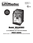
TASK FORCE TIPS
MANUAL: Ice-Control
Anti-icing & Deicing Nozzles
INSTRUCTIONS FOR SAFE OPERATION AND MAINTENANCE
WARNING
Read instruction manual before use. Operation of this nozzle without understanding the manual
and receiving proper training can be dangerous and is a misuse of this equipment. Call 1-800-3482686 or 1-219-462-6161 with any questions.
This instruction manual is intended to familiarize ground support crew and maintenance personnel
with the operation, servicing and safety procedures associated with TFT ice-control nozzles.
This manual should be kept available to all operating and maintenance personnel.
BH-HT-PD Series
BGH-HT-PD Series
S TR E AM
F OG
F L US H
BER SERIES
BGH-HT Series
BGH-HT-IF Series
TASK FORCE TIPS, Inc.
Made in USA - www.tft.com
©Copyright Task Force Tips, Inc. 2002-2007
BH-HT Series
BH-HT-IF Series
2800 E Evans Ave • Valparaiso , IN 46383-6940 USA
800.348.2686 • 219.462.6161 • Fax 219.464.7155
LIB-205 March 1, 2007 Rev08
TABLE OF CONTENTS
4.2.1.2 ELECTRIC PATTERN CONTROL .............9
4.2.2 FLUSH CONTROL.................................................9
4.2.2.1 MANUAL CONTROL..................................9
4.2.2.2 ELECTRIC CONTROL...............................9
5.0 USE OF ICE-CONTROL NOZZLES .........................................10
6.0 FIELD INSPECTION .................................................................11
7.0 WARRANTY11
8.0 PARTS LIST 12
8.1 ICE-CONTROL NOZZLE VALVED MODELS.............12-13
8.2 ICE-CONTROL NOZZLE ELECTRIC MODEL...........14-15
8.3 12-24V ACTUATOR ASSEMBLY W/PLUG ......................16
8.4 24-36V ACTUATOR ASSEMBLY .....................................17
9.0 ANSWERS TO YOUR QUESTIONS.........................................18
10.0 INSPECTION CHECKLIST.....................................................18
1.0 MEANING OF SAFETY SIGNAL WORDS.................................2
2.0 GENERAL INFORMATION.........................................................3
2.1 VARIOUS MODELS AND TERMS ..................................3-4
3.0 FLOW CHARACTERISTICS ......................................................5
3.1 TRAJECTORY CHARTS ...................................................6
3.1.1 ANTI-ICING NOZZLES ..........................................6
3.1.2 DEICING NOZZLES...............................................7
3.1.3 ELECTRIC REMOTE NOZZLES ...........................8
4.0 NOZZLE CONTROLS.................................................................9
4.1 FLOW CONTROLS ............................................................9
4.1.1 LEVER TYPE FLOW CONTROL ...........................9
4.1.2 ELECTRIC REMOTE NOZZLE..............................9
4.2 PATTERN AND FLUSH CONTROL ...................................9
4.2.1 PATTERN CONTROL ...........................................9
4.2.1.1 MANUAL PATTERN CONTROL ................9
Note: These nozzles, while regularly used for ice control, have been modified to meet the needs of the individual aviation customers by their specifications and
requirements. As modified firefighting nozzles, Task Force Tips relies on these specifications presented by the users, and does not independently test, confirm,
or warrant, the suitability of any particular nozzle for an application. It is the responsibility of the end user to specify the flows, pressures, and configurations to
meet their requirement and application.
1.0 MEANING OF SAFETY SIGNAL WORDS
This is a safety alert symbol. Throughout the text it alerts you to potential personal injury hazards. Obey all safety messages that follow to avoid possible
injury or death.
A safety related message is identified by a safety alert symbol and a signal word to indicate the level of risk involved with a particular hazard. Per ANSI
standard Z535.4-1998 the definition of the three signal words is as follows:
DANGER
DANGER indicates an imminently hazardous situation which, if not avoided, will result in
death or serious injury.
WARNING
WARNING indicates a potentially hazardous situation which, if not avoided, could result
in death or serious injury.
CAUTION
CAUTION indicates a potentially hazardous situation which, if not avoided, may result
in minor or moderate injury.
2.0 GENERAL INFORMATION
Task Force Tips ice-control nozzles have been specifically designed to apply water, glycol or water/glycol based ice-control fluids to aircraft exterior surfaces at fluid
temperatures up to 210° F (99° C). The proper use of deicing agents aids ground support professionals in the removal of ice from aircraft fuselage, landing gear and
wing surfaces. The proper use of anti-icing agents aids ground support professionals in their efforts to prevent ice and snow from adhering to the wings of aircraft. This
may extend holdover times. These nozzles are only part of a complete ice-control system. Suitability of a particular nozzle for applying deicing or anti-icing fluids must
be determined by the end user of the nozzle.
Valved ice-control nozzles have:
• Automatic Pressure Control for optimum reach.
• Slide-Type valve with heat resistant EPDM seat - The valve design controls the flow through the nozzle while minimizing turbulence that causes
shear and degradation of Anti-icing fluids.
• Pattern Control - This nozzle features a "toothless" bumper to reduce turbulence and can be easily adjusted for any desired spray pattern between
a straight stream or wide spray position.
• Pistol Grip - (BGH models only) The pistol grip and flow control handle are insulated to protect the operator from the high temperatures
generated by fluids passing through the nozzle. Color coded pistol grips and valve handle covers are available from Task Force Tips, Inc. in black
(standard), green, red, blue, orange, yellow, and white. All valved nozzles are shipped with black handle covers. All pistol grip style nozzles are
shipped with black pistol grip and a return card which may be returned to request a free color coded pistol grip and valve handle of your choice.
The Society of Automotive Engineers (SAE) G-12E subcommittee, Aircraft Ground Deicing Equipment, has accepted the following color-coding for deicing
and anti-icing fluids.
Deicing Fluid — Red with Yellow Stripe
Anti-icing Fluid — Green with Yellow Stripe
Two pistol grips with the above coding are included with each BGH model nozzle if you wish to follow this practice.
• One-Twist Flushing - Easily flushable while flowing to clear trapped debris.
• Warranty - TFT's five-year warranty and unsurpassed service with 24-hour factory turnaround time.
©Copyright Task Force Tips, Inc. 2002-2007
2
LIB-205 March 1, 2007 Rev08
Electric remote control ice-control nozzles have:
• Automatic Pressure Control for optimum reach.
• Pattern Control- Electrically operated pattern adjustment, features a "toothless" bumper to reduce turbulence, and can
be easily adjusted for any desired spray pattern between a straight stream or wide spray position.
• Sealed electric motor with easy to use manual override.
• Flush - Easily flushable while flowing to clear trapped debris.
• Swivel connecting coupling for ease of installation.
• Warranty - TFT's five-year warranty and unsurpassed service with 24-hour factory turnaround time.
2.1 VARIOUS MODELS AND TERMS
ANTI-ICING NOZZLES - FOR USE WITH ANTI-ICING FLUIDS
MODEL
FLOW
RANGE (4)
BER-HT75
10-60 gpm***
38-227 lpm***
BER-HT75-HV
NOMINAL (5)
PRESSURE
STANDARD
COUPLING
VALVED
PATTERN
CONTROL
FIGURE
75 psi
5 bar
1.5"-9 NH
NO
ELECTRIC
(12-24VDC)
1
10-60 gpm***
38-227 lpm***
75 psi
5 bar
1.5"-9 NH
NO
ELECTRIC
(24-36VDC)
1
BGH-HT75-PD
10-60 gpm***
38-227 lpm***
75 psi
5 bar
1.0"-11.5 NPT
YES
MANUAL TWIST
2
BH-HT75
10-60 gpm***
38-227 lpm***
75 psi
5 bar
1.5"-9 NH
YES
MANUAL TWIST
5
BGH-HT50
10-60 gpm***
38-227 lpm***
50 psi
3 bar
1.5"-9 NH
YES
MANUAL TWIST
4
BH-HT50
10-60 gpm***
38-227 lpm***
50psi
3 bar
1.5"-9 NH
YES
MANUAL TWIST
5
BGH-HT50-DS
10-60 gpm***
38-227 lpm***
50 psi
3 bar
1.312"-12 SAE
YES
MANUAL TWIST
4
BGH-HT50-PD
10-60 gpm***
38-227 lpm***
50 psi
3 bar
1.0"-11.5 NPT
YES
MANUAL TWIST
2
BH-HT50-IF
10-60 gpm***
38-227 lpm***
50 psi
3 bar
1.5"-11.5 NPSH
YES
MANUAL TWIST
5
DE-ICING NOZZLES - FOR USE WITH DE-ICING FLUIDS
MODEL
FLOW
RANGE (4)
NOMINAL (5)
PRESSURE
STANDARD
COUPLING
VALVED
PATTERN
CONTROL
FIGURE
BER-HT150
10-60 gpm
38-227 lpm
150 psi
10 bar
1.5"-9 NH
NO
ELECTRIC
(12-24VDC)
1
BERP-HT150*
10-60 gpm
38-227 lpm
150 psi
10 bar
1.5"-9 NH
NO
ELECTRIC
(12-24VDC)
1
BER-HT150-HV
10-60 gpm
38-227 lpm
150 psi
10 bar
1.5"-9 NH
NO
ELECTRIC
(24-36VDC)
1
BGH-HT100-PD
10-60 gpm
38-227 lpm
100 psi
7 bar
1.0"-11.5 NPT
YES
MANUAL TWIST
2
BH-HT100-PD
10-60 gpm
38-227 lpm
100 psi
7 bar
1.0"-11.5 NPT
YES
MANUAL TWIST
3
BGH-HT150-PD
10-60 gpm
38-227 lpm
150 psi
10 bar
1.0"-11.5 NPT
YES
MANUAL TWIST
2
BH-HT150-PD
10-60 gpm
38-227 lpm
150 psi
10 bar
1.0"-11.5 NPT
YES
MANUAL TWIST
3
BH-HT100-IF
10-60 gpm
38-227 lpm
100 psi
7 bar
1.5"-11.5 NPSH
YES
MANUAL TWIST
5
BGH-HT1503PD
20-25 gpm
76-95 lpm
150 psi
10 bar
1.0"-11.5 NPT
YES
MANUAL TWIST
2
©Copyright Task Force Tips, Inc. 2002-2007
3
LIB-205 March 1, 2007 Rev08
COMBINATION NOZZLES - WITH LOW FLOW FIXED GALLONAGE SETTING FOR
ANTI-ICING WITH ANTI-ICING FLUIDS AND HIGH FLOW AUTOMATIC PRESSURE
CONTROL SETTING FOR DEICING WITH DEICING FLUIDS
MODEL
ANTI-ICING
SETTING (4,5)
DEICING
SETTING (4,5)
STANDARD
COUPLING
VALVED
PATTERN
CONTROL
FIGURE
BER-HT120
20 gpm @ 50psi
76 lpm @ 3 bar
80 gpm @120 psi
303 lpm @ 8 bar
1.5"-9 NH
NO
ELECTRIC
(12-24VDC)
1
BER-HT120-HV
20 gpm @ 50psi
76 lpm @ 3 bar
80 gpm @120 psi
303 lpm @ 8 bar
1.5"-9 NH
NO
ELECTRIC
(24-36VDC)
1
BER-HT1501
20 gpm @ 50psi
76 lpm @ 3 bar
80 gpm @150 psi
303 lpm @ 10 bar
1.5"-9 NH
NO
ELECTRIC
(12-24VDC)
1
BER-HT1502
20 gpm @ 50psi
76 lpm @ 3 bar
40 gpm @ 150 psi
151 lpm @ 10 bar
1.5”-9 NH
NO
ELECTRIC
(12-24 VDC)
1
BER-HT1501HV
20 gpm @ 50psi
76 lpm @ 3 bar
80 gpm @150 psi
303 lpm @ 10 bar
1.5"-9 NH
NO
ELECTRIC
(24-36VDC)
1
BGH-HT120-PD
20 gpm @ 50psi
76 lpm @ 3 bar
80 gpm @120 psi
303 lpm @ 8 bar
1.0"-11.5 NPT
YES
MANUAL TWIST
2
BGH-HT1502PD
20 gpm @ 50psi
76 lpm @ 3 bar
40 gpm @ 150 psi
151 lpm @ 10 bar
1.0"-11.5 NPT
YES
MANUAL TWIST
2
BH-HT-120
20 gpm @ 50psi
76 lpm @ 3 bar
80 gpm @120 psi
303 lpm @ 8 bar
1.0"-11.5 NPT
YES
MANUAL TWIST
3
BH-HT120-IF
20 gpm @ 50psi
76 lpm @ 3 bar
80 gpm @120 psi
303 lpm @ 8 bar
1.5"-11.5 NPSH
YES
MANUAL TWIST
5
*** CAN BE USED FOR ANTI-ICING FLUIDS WHEN OPERATED BETWEEN 20-30 GPM
(4) CONVERSION - 1 GPM = 3.785 LITERS, (5) CONVERSION - 1 PSI = 0.067 BAR
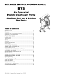
CAUTION
Mismatched or damaged threads may cause nozzle to leak heated fluid or uncouple from
hose/piping under pressure and could cause injury. Nozzle must be mated to hose/piping with
matched threads.
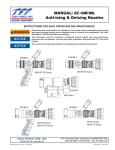
OW
FL
COUPLING
ON
CONTR
OL
STREAM
SHAPER
OFF
RUBBER
GASKET
COUPLING
S TR E AM
MANUAL
OVERRIDE KNOB
F OG
VALVED NOZZLE
and INTEGRAL PISTOL GRIP
F L US H
PISTOL
GRIP
STREAM
SHAPER
OVERRIDE
LEVER
NOZZLE WITH ELECTRIC
REMOTE PATTERN CONTROL
FIGURE 1 - COMMON MODELS AND TERMS
©Copyright Task Force Tips, Inc. 2002-2007
4
LIB-205 March 1, 2007 Rev08
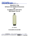
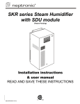
3.0 FLOW CHARACTERISTICS
Valved Ice-Control Nozzles
Flow (lpm)
0
100
200
300
400
240
BGH-HT1503
220
16
BGH-HT1502
14
200
180
BGH-HT150
BH-HT150
160
12
10
140
120
8
100
6
80
60
40
BGH-HT100
BH-HT100
20
0
4
BGH-HT120
BH-HT120
2
0
0
10
20
30
40
50
60
Flow (GPM)
70
80
90
100
110
\excel\tft\booster\ICE-CONTROL_Flow.xls[Valved Nozzles]
Valved Anti-icing Nozzles
0
50
Flow (lpm)
150
200
100
250
300
100
6
80
5
BGH-HT75
BH-HT75
60
4
3
40
2
20
BGH-HT50
BH-HT50
1
0
0
0
10
20
30
40
50
60
70
80
90
Flow (GPM)
\excel\tft\booster\ICE-CONTROL_Flow.xls[TYPE2 Nozzles]
Electric Remote Nozzles
280
260
240
220
200
180
160
140
120
100
80
60
40
20
0
50
100
150
Flow (lpm)
200
250
300
350
400
20
BER-HT1502
15
BER-HT1501
BER-HT1501HV
BER-HT150
BER-HT150-HV
10
BER-HT120
BER-HT120-HV
Pressure (bar)
Pressure (psi)
0
5
BER-HT75
BER-HT75-HV
0
0
10
20
30
40
\excel\tft\booster\ICE-CONTROL_Flow.xls[Electric Remote Nozzles]
50
60
70
80
90
100
110
Flow (GPM)
FIGURE 2 - FLOW CURVES
Friction pressure losses may vary due to differences in hoses/piping construction resulting in flows different than those shown.
Flows can be calculated using conventional hydraulics.
These flow curves are for reference only. User must determine suitability of the stream for the particular purpose for which it is
being used. Such factors as fluid/water ratio, manufacturer of fluid, fluid temperature and equipment used to supply fluid to the
nozzle may produce variation from the flows and pressures shown above.
©Copyright Task Force Tips, Inc. 2002-2007
5
LIB-205 March 1, 2007 Rev08
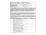
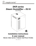
3.1 TRAJECTORY CHARTS FOR ICE-CONTROL NOZZLES
3.1.1 ANTI-ICING NOZZLES
VERTICAL DISTANCE (FEET)
50 PSI VALVED ANTI-ICING NOZZLE
50
40
30
20
10
C
CURVE
GPM
FLOW
PSI
INLET
PRESSURE
LBS
REACTION
A
B
C
D
10
20
30
40
19
45
60
64
1
4
9
13
CURVE
LPM
FLOW
KGF/CM2
INLET
PRESSURE
KGF
REACTION
A
B
C
D
38
76
110
150
1.3
3.1
4.1
4.4
.5
2.1
4.5
6.3
CURVE
GPM
FLOW
PSI
INLET
PRESSURE
LBS
REACTION
A
B
C
D
10
20
30
40
5
21
49
55
1
5
11
15
CURVE
LPM
FLOW
KGF/CM2
INLET
PRESSURE
KGF
REACTION
A
B
C
D
38
76
110
150
.3
1.4
3.4
3.8
.5
2.2
5.0
7.1
D
B
A
0
20
0
40
60
80
100
120
140
HORIZONTAL DISTANCE (FEET)
VERTICAL DISTANCE (FEET)
75 PSI VALVED ANTI-ICING NOZZLE
50
40
30
20
10
C
D
B
A
0
0
20
40
60
80
100
120
HORIZONTAL DISTANCE (FEET)
140
These trajectories, reach and reaction numbers are provided for reference. All data based on 30 degree nozzle discharge angle, in
straight stream setting. Actual trajectories, reach and reactions may vary with wind conditions, fluid type, fluid/water ratio, fluid
temperature, pressure and flow at the nozzle. It is the operator's responsibility to determine that the system provides adequate reach
for the intended purpose.
CAUTION
Deicing nozzles operate at high pressures. Direct impingement of the stream at right angles to
some aircraft surfaces may cause deformation or damage. User should direct stream at shallow
angles to sensitive surfaces.
©Copyright Task Force Tips, Inc. 2002-2007
6
LIB-205 March 1, 2007 Rev08
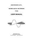
3.1.2 DEICING NOZZLES
VERTICAL DISTANCE (FEET)
100 PSI VALVED DEICING NOZZLE
PSI
INLET
PRESSURE
LBS
REACTION
50
CURVE
GPM
FLOW
40
30
A
B
C
D
20
40
50
60
64
85
95
100
8
19
25
31
CURVE
LPM
FLOW
KGF/CM2
INLET
PRESSURE
KGF
REACTION
A
B
C
D
76
150
190
230
4.4
5.9
6.6
6.9
3.8
8.8
12
15
CURVE
GPM
FLOW
PSI
INLET
PRESSURE
LBS
REACTION
A
B
C
D
20
40
60
80
50
81
105
120
7
18
31
44
CURVE
LPM
FLOW
KGF/CM2
INLET
PRESSURE
KGF
REACTION
A
B
C
D
76
150
230
300
3.4
5.6
7.2
8.3
3.4
8.6
15
21
CURVE
GPM
FLOW
PSI
INLET
PRESSURE
LBS
REACTION
A
B
C
D
10
20
30
50
40
83
114
150
3
9
16
31
CURVE
LPM
FLOW
KGF/CM2
INLET
PRESSURE
KGF
REACTION
A
B
C
D
38
76
110
190
2.8
5.7
7.9
10
1.5
4.3
7.6
15
C
20
10
D
A
B
0
0
20
40
60
80
100
120
140
HORIZONTAL DISTANCE (FEET)
VERTICAL DISTANCE (FEET)
120 PSI VALVED DEICING NOZZLE
50
40
30
20
10
C
D
B
A
0
0
20
40
60
80
100
120
140
HORIZONTAL DISTANCE (FEET)
VERTICAL DISTANCE (FEET)
150 PSI VALVED DEICING NOZZLE
50
40
30
20
10
C
D
A
0
0
20
B
40
60
80
100
120
HORIZONTAL DISTANCE (FEET)
140
These trajectories, reach and reaction numbers are provided for reference. All data based on 30 degree nozzle discharge angle, in
straight stream setting. Actual trajectories, reach and reactions may vary with wind conditions, fluid type, fluid/water ratio, fluid
temperature, pressure and flow at the nozzle. It is the operator's responsibility to determine that the system provides adequate reach
for the intended purpose.
CAUTION
Deicing nozzles operate at high pressures. Direct impingement of the stream at right angles to
some aircraft surfaces may cause deformation or damage. User should direct stream at shallow
angles to sensitive surfaces.
©Copyright Task Force Tips, Inc. 2002-2007
7
LIB-205 March 1, 2007 Rev08
VERTICAL DISTANCE (FEET)
3.1.3 ELECTRIC REMOTE NOZZLES
75 PSI ELECTRIC REMOTE CONTROL
ANTI-ICING NOZZLE
50
40
30
20
10
0
VERTICAL DISTANCE (FEET)
GPM
FLOW
PSI
INLET
PRESSURE
LBS
REACTION
A
B
C
D
10
20
30
50
19
45
60
64
2
7
12
20
CURVE
LPM
FLOW
KGF/CM2
INLET
PRESSURE
KGF
REACTION
A
B
C
D
38
76
110
190
1.3
3.1
4.1
4.4
1.0
3.2
5.5
9.5
CURVE
GPM
FLOW
PSI
INLET
PRESSURE
LBS
REACTION
A
B
C
D
20
40
60
80
50
93
106
120
7
19
31
44
CURVE
LPM
FLOW
KGF/CM2
INLET
PRESSURE
KGF
REACTION
A
B
C
D
76
150
230
300
3.4
6.4
7.3
8.3
3.4
9.2
15
21
CURVE
GPM
FLOW
PSI
INLET
PRESSURE
LBS
REACTION
A
B
C
D
20
40
60
80
74
123
136
150
9
22
35
49
CURVE
LPM
FLOW
KGF/CM2
INLET
PRESSURE
KGF
REACTION
A
B
C
D
76
150
230
300
5.1
8.5
9.4
10
4.1
11
17
23
C
D
0
A
B
20
40
60
80
100 120 140
HORIZONTAL DISTANCE (FEET)
120 PSI ELECTRIC REMOTE CONTROL
DEICING NOZZLE
50
40
30
20
10
0
C
D
B
A
0
20
40
60
80
100 120 140
HORIZONTAL DISTANCE (FEET)
VERTICAL DISTANCE (FEET)
CURVE
150 PSI ELECTRIC REMOTE CONTROL
DEICING NOZZLE
50
40
30
20
10
0
C
D
B
A
0
20
40
60
80
100 120 140
HORIZONTAL DISTANCE (FEET)
These trajectories, reach and reaction numbers are provided for reference. All data based on 30 degree nozzle discharge angle, in
straight stream setting. Actual trajectories, reach and reactions may vary with wind conditions, fluid type, fluid/water ratio, fluid
temperature, pressure and flow at the nozzle. It is the operator's responsibility to determine that the system provides adequate reach
for the intended purpose.
CAUTION
Deicing nozzles operate at high pressures. Direct impingement of the stream at right angles to
some aircraft surfaces may cause deformation or damage. User should direct stream at shallow
angles to sensitive surfaces.
©Copyright Task Force Tips, Inc. 2002-2007
8
LIB-205 March 1, 2007 Rev08
4.0 NOZZLE CONTROLS
4.1 FLOW CONTROL
4.1.1 LEVER TYPE FLOW CONTROL
On models that use a bail-type valve handle, the nozzle is shut off when the handle is fully forward. The valve handle has six detent flow
positions. These detent positions allow the nozzle operator to regulate the fluid flow of the nozzle depending on the need or what can
be safely and effectively handled.
4.1.2 ELECTRIC REMOTE NOZZLES
On models with electric remote control of the shaper there is no built-in flow control. Flow control must be provided for elsewhere in the
system.
4.2 PATTERN AND FLUSH CONTROL
4.2.1 PATTERN CONTROL
4.2.1.1 MANUAL PATTERN CONTROL
On models that use a twist-type pattern control, a continuously variable pattern from narrow to wide is available. Turning the SHAPER
clockwise, as seen from the operating position behind the nozzle, moves the SHAPER to the straight stream position. Turning the
SHAPER counterclockwise will result in an increasingly wider pattern. An indicator band on the nozzle barrel shows which position the
SHAPER is in by progressively uncovering symbols for FLUSHING, WIDE SPRAY and STRAIGHT STREAM.
4.2.1.2 ELECTRIC PATTERN CONTROL
On models that use an electric pattern control, a continuously variable pattern from narrow to wide is available by operating the electric
actuator according to the directions supplied with the actuator control panel. Extending the SHAPER outwards, as seen from behind
the nozzle, moves the SHAPER to the straight stream position. Retracting the SHAPER inwards will result in an increasingly wider
pattern. The actuator "free wheels" at each end of its stroke making limit switches unnecessary. A manual override lever on the electric
actuator, when depressed, allows the manual override knob to be turned. Turning the knob counterclockwise, as seen from the
operating position behind the nozzle, extends the SHAPER towards the straight stream position. Turning the knob clockwise retracts
the SHAPER towards the wide spray position.
CAUTION
Electric remote nozzle has finger pinch points. Keep fingers away from nozzle when using electric
control.
4.2.2 FLUSH CONTROL
Debris may get caught inside the nozzle. This trapped material will cause poor stream quality, shortened reach and reduced flow. To
remove this trapped debris, the nozzle can be flushed as follows:
4.2.2.1 VALVED NOZZLE FLUSHING
While still flowing fluid, turn the SHAPER counterclockwise past the wide spray position (increased resistance to turning will be felt on
the SHAPER as the nozzle goes into flush.) This will open the nozzle allowing debris to pass through. Rotate the SHAPER clockwise
and out of flush to continue normal operation. During flush, the nozzle will lose much of its reaction force and reach as the pressure
drops. The nozzle operator must be prepared for an increase in reaction, reach and pressure when returning the nozzle from the flush
position to normal operation to retain control of the nozzle and stream. Operating the nozzle in the flush position will flow increased
volumes of fluid. Operate in the flush position only when necessary and only for a short amount of time to prevent fluid waste.
CAUTION
Heated ice-control fluids are capable of causing burns. Direct stream away from personnel when
flushing as hot fluid may splash to the ground directly under the nozzle.
4.2.2.2 ELECTRIC REMOTE FLUSHING
While still flowing fluid, retract the SHAPER backwards past the wide spray position (as viewed from behind the nozzle) until it reaches
its stop. This will open the nozzle allowing debris to pass through. When the debris has been flushed out, extend the SHAPER outwards
until it is out of flush as determined by the markings on the barrel and the force of the stream to continue normal operation. Flushing
may also be accomplished in the manual override mode of operation by moving past the wide spray position. See 4.2.1.2 for
instruction on how to use manual override. During flush, the nozzle will lose much of its reaction force and reach as the pressure drops.
Operating the nozzle in the flush position will flow increased volumes of fluid. Operate in the flush position only when necessary to
prevent fluid waste.
WARNING
Debris in nozzle can result in ineffective stream. Flush or uncouple nozzle to remove debris.
Remove all pressure and flow from the nozzle before uncoupling.
CAUTION
Heated ice-control fluids are capable of causing burns. Direct stream away from personnel when
flushing as hot fluid may splash to the ground directly under the nozzle.
©Copyright Task Force Tips, Inc. 2002-2007
9
LIB-205 March 1, 2007 Rev08
5.0 OPERATION OF ICE-CONTROL NOZZLES
IT IS THE RESPONSIBILITY OF THE GROUND CREW MANAGEMENT TO DETERMINE PHYSICAL CAPABILITIES AND SUITABILITY
FOR AN INDIVIDUAL'S USE OF THIS EQUIPMENT.
The methods used in applying ice-control fluids to aircraft are the responsibility of the agency performing the ice-control fluid
application. Many factors contribute to the proper control of ice on an aircraft. The nozzle is only one part of a complete ice control
system. Flow, pressure at the nozzle, fluid temperature, type of fluid, method of application, outside air temperature, precipitation,
aircraft surface temperature and other factors must be taken into account when dealing with ice conditions. The proper methods must
be determined by each agency for their particular conditions.
Where a nozzle is listed as Anti-icing capable, flow and pressure must be controlled within the rating of the nozzle to minimize shearing
degradation of the fluid.
WARNING
Discharge of anti-icing fluids from nozzles at flows higher than 50 GPM or 85 psi may result in
degradation of the fluid and render it ineffective in preventing a buildup of ice on aircraft surfaces
prior to takeoff. Consult fluid manufacturer's recommended guidelines.
Rated fluid temperatures at the nozzle must not be exceeded. Use of saltwater in these nozzles is not permissible and will lead to a
shortened service life. Some features of this nozzle that the operator should be aware of are:
!
Automatic Pressure Control for deicing - When used for deicing, these nozzles from Task Force Tips incorporate a
pressure regulating mechanism, which means the fluid discharge velocity is nearly constant. With a constant nozzle
discharge pressure, the deicing agent will have optimum reach at all flow settings, thereby reducing waste due to insufficient
range of the stream.
!
Slide-Type valve with heat resistant EPDM seat - On nozzles with a valve, the valve design controls the flow through the
nozzle while minimizing turbulence that causes shear and degradation of anti-icing fluids. Because of this feature, the nozzle
can be operated at any valve handle position, thereby allowing the operator to regulate the amount of agent being applied.
This gives the operator the ability to conserve fluid and minimize waste without sacrificing reach or range of the stream. Unlike
a ball valve, the stainless steel slide valve is not directly in the flow path and will not tighten under pressure, or bind with age.
Therefore, it remains easy to operate.
!
Pattern Control - This nozzle features a "toothless" bumper to reduce turbulence and can be easily adjusted for any desired
spray pattern by moving the shaper between a straight stream or wide spray position. This will be beneficial when applying
fluids to sensitive areas of the aircraft.
!
Sealed electric motor with easy-to-use manual override - On electric remote models, the nozzle is equipped with a sealed
motor/gear housing which prevents contamination of the actuator with dirt and fluids. The actuator features an easy-to-use
override mechanism to allow manual setting of the pattern or to place the nozzle into flush mode.
!
Flushable while flowing - The nozzle shaper, when retracted fully, puts the nozzle into flush, providing an oversized fluid
passageway which allows trapped debris to exit the nozzle. On manual models, an increase in turning force on the shaper
signals the operator that the nozzle is moving into flush.
DANGER
An inadequate supply of nozzle pressure and/or flow will cause an ineffective stream and can result
in incomplete removal or incomplete protection from the build-up of ice on flight surfaces which
may lead to injury, death or loss of property. Call 800-348-2686 for assistance.
WARNING
Ice-control fluid streams are capable of injury and damage. Heated streams can cling to and burn
unprotected flesh and eyes. Do not direct fluid stream or allow splash to cause injury to persons or
property.
WARNING
Failure to restrain nozzle reaction can cause injury from loss of footing and/or whipping. With
handheld nozzles, the nozzle operator must always be positioned to restrain the nozzle reaction in
the event of those changes. In case of whipping, retreat from the nozzle immediately. Do not
attempt to regain control of nozzle while flowing fluid.
WARNING
Breathing ice-control fluid fumes can be hazardous to your health. Avoid working downwind. Avoid
splash back. Consult fluid manufacturer's safety guidelines.
©Copyright Task Force Tips, Inc. 2002-2007
10
LIB-205 March 1, 2007 Rev08
6.0 FIELD INSPECTION
Task Force Tip's Ice-Control Nozzles are designed and manufactured to be damage resistant and require minimal maintenance.
However, as the primary fluid application tool upon which aircraft ice-control depends, they should be treated accordingly.
WARNING
Nozzle must be periodically inspected for proper operation and function according to Inspection
Checklist in section 10.0. Any nozzle that fails inspection is dangerous to use and must be repaired
before using.
Performance tests shall be conducted on Ice-Control nozzles after repair, or anytime a problem is reported to verify operation in
accordance with TFT test procedures. Consult factory for the procedure that corresponds to the model and serial number of the
nozzle. Any equipment which fails the related test criteria should be removed from service immediately. Equipment can be returned to
the factory for service and testing.
Factory service is available with repair time seldom exceeding one day in our facility. Factory serviced nozzles are repaired by
experienced technicians to original specifications, fully tested and promptly returned. Any returns should include a note as to the
nature of the problem, who to reach in case of questions and if a repair estimate is required. A service request form is available on our
website, www.tft.com.
Repair parts are available for those wishing to perform their own repairs. Task Force Tips assumes no liability for damage to equipment
or injury to personnel that is a result of user service.
CAUTION
Any alterations to the nozzle and its markings could diminish safety and constitutes a misuse of
this product. Do not alter the nozzle or its markings.
All Task Force Tip nozzles are factory lubricated with high quality silicone grease. This lubricant has excellent washout resistance and
long term performance. If your operation has unusually hard or sandy water, the moving parts may be affected. Foam agents and water
additives contain soaps and chemicals that may break down the factory lubrication.
The moving parts of the nozzle should be checked on a regular basis for smooth and free operation, and signs of damage. IF THE
NOZZLE IS OPERATING CORRECTLY, THEN NO ADDITIONAL LUBRICATION IS NEEDED. Any nozzle that is not operating correctly
should be immediately removed from service and the problem corrected.
For recommended lubrication, view service manual (LIB-020) for your specific model.
7.0 WARRANTY
Task Force Tips, Inc., 2800 East Evans Avenue, Valparaiso, Indiana 46383-6940 USA ("TFT") warrants to the original purchaser of its
Ice-Control series nozzles ("equipment"), and to anyone to whom it is transferred, that the equipment shall be free from defects in
material and workmanship during the five (5) year period from the date of purchase.
TFT's obligation under this warranty is specifically limited to replacing or repairing the equipment (or its parts) which are shown by
TFT's examination to be in a defective condition attributable to TFT. To qualify for this limited warranty, the claimant must return the
equipment to TFT, at 2800 East Evans Avenue, Valparaiso, Indiana 46383-6940 USA, within a reasonable time after discovery of the
defect. TFT will examine the equipment. If TFT determines that there is a defect attributable to it, TFT will correct the problem within a
reasonable time. If the equipment is covered by this limited warranty, TFT will assume the expenses of the repair.
If any defect attributable to TFT under this limited warranty cannot be reasonably cured by repair or replacement, TFT may elect to
refund the purchase price of the equipment, less reasonable depreciation, in complete discharge of its obligations under this limited
warranty. If TFT makes this election, claimant shall return the equipment to TFT free and clear of any liens and encumbrances.
This is a limited warranty. The original purchaser of the equipment, any person to whom it is transferred and any person who is an
intended or unintended beneficiary of the equipment, shall not be entitled to recover from TFT any consequential or incidental
damages for injury to person and/or property resulting from any defective equipment manufactured or assembled by TFT. It is agreed
and understood that the price stated for the equipment is in part consideration for limiting TFT's liability. Some states do not allow the
exclusion or limitation of incidental or consequential damages, so the above may not apply to you.
TFT shall have no obligation under this limited warranty if the equipment is, or has been, misused or neglected (including failure to
provide reasonable maintenance) or if there have been accidents to the equipment or if it has been repaired or altered by someone
else.
THIS IS A LIMITED EXPRESS WARRANTY ONLY. TFT EXPRESSLY DISCLAIMS WITH RESPECT TO THE EQUIPMENT ALL IMPLIED
WARRANTIES OF MERCHANTABILITY AND ALL IMPLIED WARRANTIES OF FITNESS FOR A PARTICULAR PURPOSE. THERE IS NO
WARRANTY OF ANY NATURE MADE BY TFT BEYOND THAT STATED IN THIS DOCUMENT.
This limited warranty gives you specific legal rights, and you may also have other rights which vary from state to state.
©Copyright Task Force Tips, Inc. 2002-2007
11
LIB-205 March 1, 2007 Rev08
8.0 PARTS LIST
8.1 ICE-CONTROL NOZZLE VALVED MODELS
MODEL NUMBER
REF #
QTY
(a)
(b)
(c)
(d)
(e)
(k)
(n)
BGH-HT50
BH-HT50
BGH-HT50-DS
BGH-HT50-PD
BGH-HT75-PD
BH-HT50-IF
BH-HT75
(f)
(g)
(h)
(i)
(j)
(l)
(m)
BGH-HT100-PD
BH-HT100-PD
BGH-HT120-PD
BGH-HT150-PD
BH-HT150-PD
BH-HT120-PD
BH-HT120-IF
(o) BGH-HT1502PD
(p) BGH-HT1503PD
DESCRIPTION
1
1
B504
B504
BUMPER NO TEETH
2
1
B510
B510
SHAPER GUIDE
3
1
B524
B524
BARREL CONE
4
1
B560
B560
BAFFLE
5
1
B568 (a,b,c,d,k)
—
50 PSI SPRING WASHER
1
B567 (e,n)
—
75 PSI SPRING WASHER
1
—
B565 (f,g)
100 PSI SPRING WASHER
1
—
B563 (h,l,m)
120 PSI SPRING WASHER
1
—
B566 (i,j)
150 PSI SPRING WASHER
1
—
B561 (o)
150 PSI SPRING WASHER
1
—
B559(p)
150 PSI SPRING WASHER
6
1
B594
B594
HIGH-TEMP NOSE CONE
7
1
B622
B622
WIDE HANDLE
4
VT08E32BH375
VT08E32BH375
#8-32X3/8 BUTTON HEAD SCREW
2
HM625-BLK
HM625-BLK
HANDLE COVER
8
1
B630
B630
CAM SCREW
9
1
B635
B635
SAFETY SCREW
10
4
B650
B650
DRAG NUBS
11
1
B662
B662
SPECIAL AGENT SLIDER
©Copyright Task Force Tips, Inc. 2002-2007
— Continued on next page —
12
LIB-205 March 1, 2007 Rev08
8.1 ICE-CONTROL NOZZLE VALVED MODELS - cont.
MODEL NUMBER
(a)
(b)
(c)
(d)
(e)
(k)
(n)
REF #
BGH-HT50
BH-HT50
BGH-HT50-DS
BGH-HT50-PD
BGH-HT75-PD
BH-HT50-IF
BH-HT75
(f)
(g)
(h)
(i)
(j)
(l)
(m)
BGH-HT100-PD
BH-HT100-PD
BGH-HT120-PD
BGH-HT150-PD
BH-HT150-PD
BH-HT120-PD
BH-HT120-IF
QTY
(o) BGH-HT1502PD
(p) BGH-HT1503PD
DESCRIPTION
12(d,e,f,g,h,i,l,o)
1
B668
B668
1.0" TAPER PIPE COUPLING
12(a,b,n)
1
B694N
—
1.5" NH ROCKER LUG
12(k,m)
1
B694I
—
1.5" NPSH ROCKER LUG
12(c)
1
B680DS
—
CODE DS COUPLING 1 5/16-12
14
1
B727
B727
NAME LABEL - ICE CONTROL
16
1
B740
B740
BARREL LABEL
17
1
B750
B750
VALVE LABEL
18
1
B770
B770
PORT PLUG
19
1
B785
B785
FLUSH WAVE SPRING
20
1
B540
B540
BARRELL
1
B570 (e,n)
B570 (f,g,h,i,l,o,p)
SHAFT
1
B574 (a,b,c,d,k)
—
ANTI-ICING SHAFT
1
B584
B584
HIGH TEMP SPRING CAN
1
B760 (a,b,c,d,k)
B760 (f,g,h,i.l)
CONTROL SPRING 100 PSI
1
B765 (e,n)
—
FORESTRY SPRING 75 PSI
1
—
B766 (i,j)
CONTROL SPRING 150 PSI
1
—
B767 (o,p)
CONTROL SPRING 1502
1
—
B572 (h,i,j,l,m,o,p)
150 PSI SPRING SPACER
21
1
B910
B910
VALVE ASSEMBLY
22
28
V2120
V2120
3/16" DIA. STAINLESS BALL
23
2
V2120-TORLON
V2120-TORLON
3/16" DIA. TORLON BALL
24
4
V2130-TORLON
V2130-TORLON
7/32" DIA. TORLON BALL
25
46
V2135
V2135
1/8" DIA. NYLON BALL
26
1
V3040
V3040
1.0" COUPLING GASKET
27
1
V3130
V3130
1.5" COUPLING GASKET
28
1
V4270
V4270
WS-128-F-S02 SMALLEY RING
29
2
V4280
V4280
WSM-50-S02 SMALLEY RING
30
2
VM4195
VM4195
SPRING #C0180-032-0310-S
31
1
VO-030
VO-030
O-RING-030
32
1
VO-127
VO-127
O-RING-127
33
1
VO-128
VO-128
O-RING-128
34
1
VOQ-4124
VOQ-4124
QUADX-4124
35
1
VOQ-4216
VOQ-4216
QUADX-4216
36
1
VOQ-4225
VOQ-4225
QUADX-4225
37
2
VT10Y32SS187
VT10Y32SS187
#10-32 x 3/16" SOCKET SET SCREW
38
2
VT31E18BH500
VT31E18BH500
5/16-18 x 1/2" BUTTON HEAD
40
1
VT37-24SS750
VT37-24SS750
3/8-24 x 3/4" SOCKET SET SCREW
42
1
VT37-16SS312
VT37-16SS312
3/8-16 X 5/16 SOCKET SET
43
1
HM693-U
HM693-U
GRIP SPACER - ULTIMATIC
44
1
HM692-BLK
HM692-BLK
PISTOL GRIP - BLACK
1
HM994-KIT
HM994-KIT
GRIP COLOR CODED SUBASSEMBLY - 1 EACH
1
VT37-16SH1.0
VT37-16SH1.0
RED W/YELLOW & GREEN W/YELLOW STRIPE
45
©Copyright Task Force Tips, Inc. 2002-2007
13
3/8-16 X 1.00 SHCS
LIB-205 March 1, 2007 Rev08
8.2 ICE-CONTROL NOZZLE ELECTRIC REMOTE MODEL
16
10
3
4
5
17
20
1
14
27
15
25
26
24
18
23
6
2
8
11
19
28
13
9
29
21
12
22
MODEL NUMBER
Part # For 12-24 VDC
(a) BER-HT75
(b) BER-HT120
(c) BER-HT150
(d) BER-HT1501
(i) BER-HT1502
(j) BERP-HT150
Part # For 24-36 VDC
(e) BER-HT75-HV
(f) BER-HT120-HV
(g) BER-HT150-HV
(h) BER-HT1501HV
REF #
QTY
1
1
B504
B504
BUMPER / NO TEETH
2
1
B514
B514
ER SHAPER GUIDE
3
1
B524
B524
BARREL CONE
4
1
B560
B560
BAFFLE
5
1
B567 (a)
B567 (e)
75 PSI SPRING WASHER
1
B563 (b)
B563 (f)
120 PSI SPRING WASHER
1
B566 (c, j)
B566 (g)
150 PSI SPRING WASHER
1
B562 (d)
B562 (h)
SPRING WASHER SPECIAL
1
—
B561 (i)
DESCRIPTION
SPRING WASHER 20 GPM @ 50 PSI
SPRING WASHER 40 GPM @ 150 PSI
6
1
B597
B597
HIGH TEMP NOSE CONE
8
1
B727
B727
ICE-CONTROL NAME LABEL
9
1
B740
B740
BARREL LABEL
— Continued on next page —
©Copyright Task Force Tips, Inc. 2002-2007
14
LIB-205 March 1, 2007 Rev08
8.2 ICE-CONTROL NOZZLE ELECTRIC REMOTE MODEL - cont.
MODEL NUMBER
REF #
QTY
10
11
1
1
1
1
1
1
1
1
1
1
1
1
1
4
46
1
1
1
1
1
1
2
1
1
2
2
1
1
34
1
12
13
14
15
16
17
18
19
20
21
22
23
24
25
26
27
28
29
Part # For 12-24 VDC
(a) BER-HT75
(b) BER-HT120
(c) BER-HT150
(d) BER-HT1501
(i) BER-HT1502
(j) BERP-HT150
B785
B544
B570
B584
B572 (b,c,d, j)
B763 (b)
B765 (a)
B766 (c,d)
—
VO-115
B935 (a,b,c,d,i)
—
B945-ICE (j)
V2130-TORLON
V2135
V3130
V4270
V4280
VO-030
VO-128
VOQ-4225
VT25-20SH3.0
VT31-18BH1.4
VT37-24SS750
VT10Y32SS250
VT25-20SS375
B663
F10097N
V2120
B770
©Copyright Task Force Tips, Inc. 2002-2007
Part # For 24-36 VDC
(e) BER-HT75-HV
(f) BER-HT120-HV
(g) BER-HT150-HV
(h) BER-HT1501HV
DESCRIPTION
B785
B544
B570
B584
B572 (f,g,h,i)
B763 (f)
B765 (e)
B766 (g,h)
B767 (i)
VO-115
—
B936
—
V2130-TORLON
V2135
V3130
V4270
V4280
VO-030
VO-128
VOQ-4225
VT25-20SH3.0
VT31-18BH1.4
VT37-24SS750
VT10Y32SS250
VT25-20SS375
B663
F10097N
V2120
B770
15
FLUSH WAVE SPRING
LINEAR BARREL
SHAFT
HI-TEMP SPRING CAN
SPRING SPACER - 150 PSI
SPRING 80 PGM @ 120 PSI
FORESTRY SPRING 75 PSI
CONTROL SPRING 150 PSI
CONTROL SPRING 1502
O-RING-115
12 VDC CAST ACTUATOR ASSEMBLY
24 VDC CAST ACTUATOR ASSEMBLY
12 VDC CAST ACTUATOR ASSEMBLY W/PLUG
7/32 BALL TORLON
1/8 BALL - #101 NYLON
COUPLING GASKET 1.5"
WS-128-F-S02 SMALLEY RING
WSM-50-S02 SMALLEY RING
O-RING-030
O-RING-128
QUAD RING-225
1/4-20 x 3 SOCKET HEAD CAP
5/16-18 x 1-7/16 BHCS
3/8-24 x 3/4 SOCKET SET
10-32 x ¼ SET SCREW ND PATCH
1/4-20 x 3/8 SOCKET SET
BASE ER SWIVEL
1.5" NH ROCKER LUG
3/16" DIA. STAINLESS BALL
PORT PLUG
LIB-205 March 1, 2007 Rev08
8.3 12-24V ACTUATOR ASSEMBLY WITH PLUG
ACTUATOR MODELS: B945, B945-ICE, HM945, M945, MD945, MS945
REF#
1
2
3
5
6
7
8
9
10
13
14
15
16
17
18
19
20
21
22
24
25
26
31
32
33
34
35
36
37
38
39
©Copyright Task Force Tips, Inc. 2002-2007
DESCRIPTION
10-32 x ½ Button Head Electropolish
Actuator Cover 12-24 VDC
O-Ring-146
#6-32 x 3/8 Socket Head
24 VDC Motor 30:1/36 VDC Motor 30:1
ER Motor Mount
Cam Machined
3/8-24 x 3/8 Dog Point
Strain Relief PG9 .31Hole
Knob - Hardcoat
O-Ring-109
ER Actuator Spring
10-32 x ¼ SS ND Patch
Washer
1/8 x ¾ HDP Spirol Pin
Cam Lever - Hardcoat
Lever Spring
5/32 x 7/8 HDP Spirol Pin
O-Ring-122
Screw Assembly
Actuator Tube
Actuator Housing - Laser
10-32 X 1/2 Socket Set Screw Cone Point
O-Ring-011
4-40 X 1/4 Socket Head Cap Screw
8-32 X 5/8 Button Head Cap Screw
Board - Nozzle Actuator Id
Magnet - 1" OD 30 Pole
Sensor - Hall Effect 3 Wire 4.5-24 Volts
Cable - 6 Pole Male In-Line Plug
Spacer - Round Aluminum Thru-Hole
16
QTY
4
1
1
2
1
1
1
3
1
1
2
1
3
1
1
1
1
1
1
1
1
1
1
1
1
2
1
1
1
1
2
PART #
VT10E32BH500
M051-L
VO-146
VT06-32SH375
M044
M058
M049
H515
Y5245
M052
VO-109
VM4196
VT10Y32SS250
M053
VP125X750H
M054
M055
V1900
VO-122
B041, H041, M041, MS041
B104, H104, M104, MS105
M050
VT10-32CP500
VO-011
VT04-40SH250
VT08-32BH625
Y5460
Y5465
Y5470
Y5480
Y5537
LIB-205 March 1, 2007 Rev08
8.4 24-36V ACTUATOR ASSEMBLY
ACTUATOR MODELS: B936, M936, MS936
REF#
1
2
3
4
5
6
7
8
9
10
11
12
13
14
15
16
17
18
19
20
21
22
24
25
26
29
30
31
©Copyright Task Force Tips, Inc. 2002-2007
DESCRIPTION
QTY
10-32 x ½ Button Head Electropolish
4
Actuator Cover 24-36 VDC
1
O-Ring-146
1
8-32 x .375 Button Head Electropolish
2
#6-32 x 3/8 Socket Head
2
36VDC Motor 30:1 Worm
1
ER Motor Mount
1
Cam Machined
1
3/8-24 x 3/8 Dog Point
3
Strain Relief PG9 .31Hole
1
#6 Sealed Spade Term. 18-22 GA.
4
18/2 SJOOW 600 Volt Black
6
Knob - Hardcoat
1
O-Ring-109
2
ER Actuator Spring
1
10-32 x ¼ SS ND Patch
3
Washer
1
1/8 x ¾ HDP Spirol Pin
1
Cam Lever - Hardcoat
1
Lever Spring
1
5/32 x 7/8 HDP Spirol Pin
1
O-Ring-122
1
Screw Assembly
1
Actuator Tube
1
Actuator Housing - Laser
1
Terminal Block - 2 Pos. 20 A 150 V #6 SCR
1
Cord Protector
1
10-32 X 1/2 Socket Set Screw Cone Point
1
17
PART #
VT10E32BH500
M051-H
VO-146
VT08E32BH375
VT06-32SH375
H046
M058
M049
H515
Y5245
V4103
V4075
M052
VO-109
VM4196
VT10Y32SS250
M053
VP125X750H
M054
M055
V1900
VO-122
B041, M041, MS041
B104, M104, MS105
M050
V4145
VM4093
VT10-32CP500
LIB-205 March 1, 2007 Rev08
9.0 ANSWERS TO YOUR QUESTIONS
We appreciate the opportunity of serving you and making your job easier. If you have any problems or questions, our tollfree "Hydraulics Hotline", 800-348-2686, is normally available to you 24 hours a day, 7 days a week.
10.0 INSPECTION CHECKLIST
Nozzle must be inspected periodically for proper operation and function according to this checklist periodically.
On models with a hand operated valve, check that:
1) There is no obvious damage such as missing, broken or loose parts, damaged labels, etc.
2) Coupling is tight and leak free.
3) Valve operates freely through full range of settings.
4) "OFF" position does fully shut off and flow stops.
5) Nozzle flow is adequate as indicated by pump pressure and nozzle reaction.
6) Shaper turns freely and adjusts pattern through full range.
7) Shaper turns into full flush and out of full flush with normal flow and pressure restored.
On models with an electric remote control, check that:
1) There is no obvious damage such as missing, broken or loose parts, damaged labels, frayed or cracked wiring, etc.
2) Coupling is tight and leak free.
3) Nozzle flow is adequate as indicated by pump pressure and nozzle reach.
4) Shaper moves freely and adjusts pattern through full range by electric and manual control.
5) Shaper moves into full flush and out of full flush with normal flow and pressure restored by electric and manual control.
6) Electric remote actuator mountings are tight.
7) Manual override controls operate freely and through full range of motion.
WARNING
Any ice-control nozzle failing any part of the inspection checklist is unsafe. Correct this problem
before use. Operating a nozzle that fails any of the above inspections is a misuse of this equipment.
TASK FORCE TIPS, Inc.
Made in USA - www.tft.com
©Copyright Task Force Tips, Inc. 2002-2007
2800 E Evans Ave • Valparaiso , IN 46383-6940 USA
800.348.2686 • 219.462.6161 • Fax 219.464.7155
LIB-205 March 1, 2007 Rev08