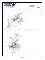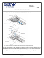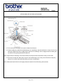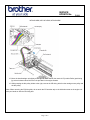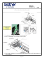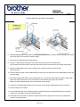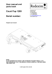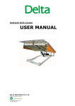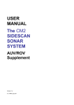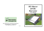
1
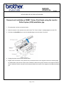
SERVICE
UPDATE No.
F1323
MFCJ6510DW, MFCJ6710DW, MFCJ6910DW
Removal and Installation of BHM11 Series Print Heads using the Leveller
Roller System (LRS) installation jigs.
1. Plug the power cord into an electrical outlet.
2. Open the scanner cover (scanner unit) until it locks. The "Cover is Open." message appears on the LCD.
3. Hold down the Stop/Exit key to move the head/carriage unit to the center of its travel.
4. Unplug the power cord from the electrical outlet.
5. Slightly close the scanner cover (scanner unit) so that the scanner cover support comes to be almost upright.
As shown below, press the rib of the section outwards in which the top of the scanner cover support is fitted in
order to widen the section, and pull out the boss provided on the top left of the support to the right and towards
you.
Page 1 of 9
SERVICE
UPDATE No.
F1323
MFCJ6510DW, MFCJ6710DW, MFCJ6910DW
6. Remove the CIS flat cable cover and the harness cover by inserting the tip of a flat screwdriver into
the slots (indicated by arrows in the figure below) and lifting up those covers. For easier removal,
start from the rear and finally pull out the tabs.
7. Move the head/carriage unit to the left end of its travel (to the place where the whole of the head/carriage unit
can be seen) by hand.
Page 2 of 9
SERVICE
UPDATE No.
F1323
MFCJ6510DW, MFCJ6710DW, MFCJ6910DW
8. Insert the tip of a flat screwdriver into the square hole provided in the head cover to release the latch in the
direction of the arrow, then release other three latches and lift up the head cover.
9. Unlock the connector on the carriage PCB and disconnect the carriage-head flat cable.
Note: After disconnecting the flat cable, check that it is not damaged at its end or short-circuited. When connecting the
flat cable, do not insert it at an angle. After insertion, check again that it is not at an angle and then lock the connector.
10. Slightly pull up the front end of the carriage PCB to release the PCB from the lock spring, take the head flat
cables out of the cable guide on the head/carriage unit, then release the hole provided in the film from the
boss.
Page 3 of 9
SERVICE
UPDATE No.
F1323
MFCJ6510DW, MFCJ6710DW, MFCJ6910DW
11. Take the carriage PCB ASSY out of the head/carriage unit and put it on the upper cover in front of the
head/carriage unit.
12. Pull out the joint leaf spring to the right to release the head joint.
13. Pull the head joint up and off the head/carriage unit. Immediately, wrap the head joint in a clean, lint-free cloth
and keep it higher than the ink supply tubes to prevent ink remaining in the ink supply tubes from leaking and
the machine from getting stained with leaked ink.
Note: Wipe off the ink remaining on the section where the head joint was mounted with a clean, lint-free cloth.
14. Remove the head joint rubber (that is a part of the head/carriage unit but may come off with the head joint)
and put it on a clean vinyl sheet while taking care not to contaminate it.
Note: Make sure that all of the four ink supply tubes are routed in front of the tube guide as shown
Page 4 of 9
SERVICE
UPDATE No.
F1323
MFCJ6510DW, MFCJ6710DW, MFCJ6910DW
15. Move the head/carriage unit slightly to the right as shown below, then set the LR (Leveller Roller) positioning
jig so that its bottom boss fits in the hole provided in the engine chassis.
16. While pressing the idle pulley holder to the right, remove the CR timing belt from the carriage motor pulley and
the idle pulley.
Note: When removing the CR timing belt, do not touch the CR encoder strip or the lubrication area on the engine unit
with your hands or with the CR timing belt.
Page 5 of 9
SERVICE
UPDATE No.
F1323
MFCJ6510DW, MFCJ6710DW, MFCJ6910DW
17. Loosely tie the CR timing belt in a bundle on the head/carriage unit.
18. Move the head/carriage unit to the left end of its travel by hand.
19. Press the right and left tabs of the leveller roller (LR) ASSY inwards to release the ASSY downwards from the
head/carriage unit.
Page 6 of 9
SERVICE
UPDATE No.
F1323
MFCJ6510DW, MFCJ6710DW, MFCJ6910DW
20. Slightly lift up the rear end of the head/carriage unit to release it from the CR guide rail (through the two cutouts), then release the front end from the CR support chassis and take the head/carriage unit up and out of
the machine.
Note: Do not touch the head nozzles (the printing ends) or ink supply ports (to which ink supply tubes are connected)
of the head/carriage unit; doing so will not only stain your hands with ink but also damage the nozzles and supply
ports. If you do touch them though, clean them with a special-purpose cleaning stick and liquid.
21. Remove the CR timing belt from the head/carriage unit.
22. Press the rear ends of the leveller roller ASSY inwards and take them out through the two cut-outs provided in
the CR guide rail.
- Assemble procedure
1. Set the leveller roller ASSY.
2. When mounting a new head/carriage unit, apply the specified lubricant to the specified points on the unit.
3. When mounting the CR timing belt, insert it into the slit provided in the head/carriage unit so that the toothed
side faces inwards as shown below. Make sure that the belt is fully inserted inside the latches
4. First fit the front end of the head/carriage unit over the CR support chassis and then set the rear end onto the
CR guide rail. Make sure that the hook provided on the bottom of the head/carriage unit catches the front edge
of the CR support chassis and the two rear bosses are fitted in the two cut-outs in the CR guide rail.
5. Set the leveller roller (LR) fitting jig on the head/carriage unit vertically and then tilt it towards you, as shown
below. This pushes the LR fitting jig rearwards and upwards, fitting the leveller roller (LR) ASSY over the
head/carriage unit.
Page 7 of 9
SERVICE
UPDATE No.
F1323
MFCJ6510DW, MFCJ6710DW, MFCJ6910DW
6. Slide the head/carriage unit by hand to check that it moves smoothly. If it does not move smoothly, the leveller
roller (LR) ASSY is not in place. Go back to step 5.
7. Remove the LR fitting jig and LR positioning jig.
8. Untie the CR timing belt loosely tied. First, at the left end, set the belt on the idle pulley.
Next, press the idle pulley holder to the right and at the right end, set the belt on the carriage motor pulley.
9. Slide the head/carriage unit by hand to check that it smoothly moves to the right and left
ends of its travel.
10. Set the head joint rubber on the head/carriage unit and secure the head joint to the head/carriage unit with the
joint leaf spring.
11. Mount the carriage PCB ASSY on the head/carriage unit, route the head flat cables through the cable guide,
and fit the hole provided in the film over the boss on the head/carriage unit as shown below.
Make sure that the head/carriage unit is secured with the lock spring.
12. Connect the carriage-head flat cable to the connector on the carriage PCB and then lock the connector.
13. Set the head cover into place.
14. If a new head/carriage unit is mounted, apply the specified lubricant to the specified points on the sliding
surface of the CR guide rail and CR support chassis.
15. Check that the CR encoder strip and PF encoder disk are free of grease and ink. If they are stained with
grease or ink, replace them.
Page 8 of 9
SERVICE
UPDATE No.
F1323
MFCJ6510DW, MFCJ6710DW, MFCJ6910DW
16. Slide the head/carriage unit by hand to check that it smoothly moves to the right and left ends of its travel. At
the same time, check that the ink supply tubes and head flat cables are not twisted.
17. If a new head/carriage unit is mounted, make adjustments specified in section 4.1 of the Service Manual.
Page 9 of 9