1
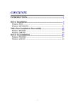
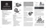
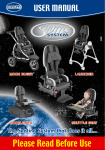
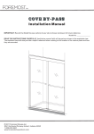
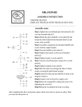
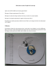
CROSSRUNNER 50
ATV - All Terrain Vehicle
Age Category: Youth Model Y-6
Only riders age 6 years or older and less than 100 lbs may ride this bike
REASSEMBLY MANUAL
Note: This ATV was fully assembled and tested at the CROSSRUNNER factory.
It was partially disassembled before shipping. This manual gives specific
instructions on how to fully re-assemble and check the unit.
Follow all steps closely to assure a safe and long lasting vehicle!
1
ReAssembly Guide
CROSSRUNNER 50 ATV
This page intentionally left blank
2
ReAssembly Guide
CROSSRUNNER 50 ATV
ATTENTION:
Always read everything before doing anything.
This will help you to know that you have access
to all the tools, information, and help you may
need to perform all the steps outlined in this
manual. Your attention to detail is critical in
providing a safe and reliable product to your
customer. There cannot be enough emphasis
placed on safety when assembling or servicing
this ATV. You will be referencing the Owner’s
Manual, the battery service instructions, and the
tire pressure information sticker on the front
fender as well as the Re-assembly Manual during
this procedure. If you have any questions or
concerns pertaining to the assembly or the
information found in this booklet, please call
888-520-7222
NOTE: This ATV should be assembled by the
selling dealer only. The end user should never
do the final assembly or inspection of this ATV.
© Copyright North American Imports, LLC
This work may not be copied and distributed without express written consent .
3
ReAssembly Guide
CROSSRUNNER 50 ATV
1.
Unpack. Remove shrink wrap, packing straps, and card board
box cover. Remove all bolts attaching metal frame work to steel base.
Untie wires holding tire and wheel assembly to metal frame. See that
bolts are removed that attach handle bar mounting plate and bumpers
to metal frame, if applicable, before attempting to lift metal frame
work off of base. Carefully lift metal frame work straight up to remove,
taking care not to scuff fenders or bumpers while removing. This should
not be attempted by one person alone. Two people, lifting together,
can remove the frame work without causing damage to the ATV or harm
to themselves. Remove small box from shipping frame base containing
all hardware, nuts, bolts, tool kit, battery and acid.
Step1-Fig1-Unpack
Step1-Fig2-Included parts
4
ReAssembly Guide
CROSSRUNNER 50 ATV
2.
Each ATV is shipped with a desiccant bag that is designed to
absorb moisture during shipping. It is of no further value once the
shipping container is opened and should be discarded immediately to
avoid being played with by children or pets.
Step2-Fig1-Desiccant bag
3.
Set parking brake for rear wheels to prevent ATV from rolling off
packing frame base. Lift and support the front end of the ATV with a
suitable jack and jack stand that allows the vehicle to remain stable
while attaching the front wheels. Install the two front wheels using the
lug nuts supplied. Never use any other type lug nut to attach wheels
than what was designed for the specific type wheel and ATV.
Step3-Fig1-Set parking brake
5
ReAssembly Guide
CROSSRUNNER 50 ATV
Step3-Fig2-Jack support
4.
Evenly snug each lug nut by hand in a star pattern. Install the
wheel center caps onto the front hub washer snapping firmly into
place. Final wheel torque must be done when ATV is sitting on flat
ground. DO NOT attempt to perform final wheel torque while ATV is
supported on a jack stand.
Step4-Fig1-Hand tighened lug nuts
6
ReAssembly Guide
CROSSRUNNER 50 ATV
Step4-Fig2-Install center cap
5.
WARNING! You must use an air gauge that has increments
smaller than 1 PSI to complete this step. Improperly inflated tires can
cause loss of control. Use the valve core tool supplied with the ATV tool
kit to tighten the valve core in each valve stem before attempting to
add air. Inflate the tires to seat the bead, taking care not to exceed the
tire manufactures recommendation (printed on the tire sidewall) for
maximum pressure to seat the bead. Release air until the correct
pressure is noted on the air gauge, according to the tire pressure
information label on the front fender of the ATV. Check each valve core
for leaks and install valve stem cap.
Step5-Fig1-Valve core tool
7
ReAssembly Guide
CROSSRUNNER 50 ATV
Step5-Fig2-Air gage with .5 pound increments
6.
Remove jack or support under front end of ATV and let it rest
on all 4 wheels, release parking brake and roll off metal shipping frame
onto flat, level surface.
7.
Reset the parking brake and perform the final wheel torque
procedure. Torque all lug nuts to 26 Ft/Lbs. using a torque wrench
with the appropriate increments. Proceed in a star or criss-cross
pattern to assure uniform torque results. Install center caps on rear
wheels of ATV. Attach front bumper with bolts provided, if applicable
to your model, taking care to properly snug all bolts adequately and not
over tighten.
Step7-Fig1-Wheel torque
Step7-Fig2-Front bumper mounting
8
ReAssembly Guide
CROSSRUNNER 50 ATV
8.
Install handle bars with the bolts and hardware provided. See
that knurled areas on handle bars are evenly spaced between the two
halves of the pinch mount supports. Lightly snug attaching bolts and
then position handle bars at the desired angle best suited for the
comfort and safety of the rider so that all hand controls are easily
accessed and operated. The angle of the hand controls is adjustable, as
well, by loosening the screws on the underside of the control and
pivoting to the desired position, then tightening screws. Turn wheels to
full left and full right positions to assure adequate clearance for the
rider’s legs and to check for binding cables or wiring. Finish tightening
handle bar mounting bolts evenly in a criss-cross pattern and torque to
28 Ft/Lbs.
Step8-Fig1-Torque handle bar bolts
Step8-Fig2-Adjust hand controls
9
ReAssembly Guide
CROSSRUNNER 50 ATV
9.
Install foam protection pads and cover on center bracket
attached to handle bars.
Step9-Fig1-Install handle bar pad
10.
All ATV’s are shipped with the fuel lines unhooked. Connect the
fuel supply line, coming from the fuel tank, to the fuel inlet port on the
carburetor securing it with the spring clamp provided on the fuel line.
Make sure the fuel line is routed in a manner to avoid kinks and to
allow for the proper gravity feed from the fuel tank. Do not run the fuel
line near any part of the exhaust or hot section of the engine and take
care to tuck it in away from the rider’s feet and legs so that it cannot
be snagged.
Step10-Fig1-Fuel line routing
10
ReAssembly Guide
CROSSRUNNER 50 ATV
11.
Inspect the fuel drain hose connected to the bottom of the
carburetor at the fuel bowl to assure that it is free of kinks and is
clamped or tie wrapped into place. This hose should always be heading
in a downward direction. See that the drain screw in the bottom of the
fuel bowl is seated in the closed position before adding fuel.
Step11-Fig1-Fuel drain hose routing
Step11-Fig2-Tighten fuel drain screw
11
ReAssembly Guide
CROSSRUNNER 50 ATV
12.
Install left engine side panel with the 3 screws and threaded
clips provided.
Step12-Fig1-Side panel attachment
13.
Caution! Battery acid is very caustic. Gloves and protective
clothing should be worn at all times when working with battery acid.
Any contact with skin or clothing should be flushed with water
immediately. Place battery on rubber or wood surface and carefully fill
battery according to instructions provided with the battery. When the
battery is full, install the cap and flush with water any acid that may be
on or around battery and then test for proper voltage. If the battery
meets the voltage specs called for in the battery instructions when
tested, install in ATV. The RED cables are positive (+) and the GREEN
cables are negative (-). Connect and tighten all battery cable
connections and see that the cables or any wiring cannot be pinched
when the battery cover is bolted into place. The battery has a dry
charge and should meet the 12.5-volt spec when filled with electrolyte.
If it does not meet the spec, charge according to the information
packaged with the battery and retest.
12
ReAssembly Guide
CROSSRUNNER 50 ATV
Step13-Fig1-Battery fill
Step13-Fig2-Battery installation
13
ReAssembly Guide
CROSSRUNNER 50 ATV
Step13-Fig3-Battery cover retainer
14.
Remove all plastic protective covering from shocks, seat, lights,
handle bars, etc.
15.
Inspect hose and cable routing for emission, brake, and fuel
systems. Make sure that all are secured and not able to bind, kink, or
be pinched. Keep them at least 1” or more away from any contact with
engine or exhaust.
Step15-Fig1-Example of secured cable
14
ReAssembly Guide
CROSSRUNNER 50 ATV
16.
Inspect throttle and brake cable free play adjustments. Confirm
that all locking nuts for cables are tight to avoid loss of adjustment.
See Service Manual for adjustment procedure if necessary.
Step16-Fig1-Throttle cable free-play adjustment
Step16-Fig2-Frt brake adjustment
15
ReAssembly Guide
CROSSRUNNER 50 ATV
Step16-Fig3-Rear brake cable free-play adjustment
Step16-Fig4-Rear Brake adjustment
17.
Inspect all other critical nuts and bolts to see that they are
secure even if you did not install them. Next, inspect headlight and
brake light operation, where applicable.
16
ReAssembly Guide
CROSSRUNNER 50 ATV
18.
Add fuel, turn fuel valve to ON position and inspect for leaks.
Install gas cap on fuel tank and run vent hose in front of tank, down and
away from rider to direct vented fumes below. Inspect oil level in
engine crankcase and brake fluid level in master cylinder reservoir.
Step18-Fig1-Fuel vent hose
Step18-Fig2-Oil fill location
17
ReAssembly Guide
CROSSRUNNER 50 ATV
Step18-Fig3-Brake fluid reservoir
19.
IMPORTANT! To start ATV, make sure parking brake is set, move
choke lever to closed position, hold front brake lever in, turn ignition
key to on position, flip start switch to run, push yellow start button to
engage starter. If engine does not spin over it may be necessary to push
the “energize button” on the remote kill switch, watch for the RED
light on the remote, then engage starter button.
Step19-Fig1-Remote kill switch
20.
After ATV is started, closely inspect for any fuel or oil leaks.
Confirm that parking brake holds adequately with moderate power
applied.
18
ReAssembly Guide
CROSSRUNNER 50 ATV
© Copyright North American Imports, LLC
This work may not be copied and distributed without express written consent .
19
ReAssembly Guide
CROSSRUNNER 50 ATV
Printed in USA
20