1
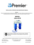
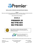
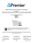
Residential Ultra Violet Disinfection System
For Residential Reverse Osmosis (RO)
Model: UV Residential Kit
Installation & Service Manual
This manual covers installation for
Standard Style & Manifold Style RO Units
UV Module
Watts Premier, Inc
8716 W. Ludlow Drive Suite #1 Peoria, AZ 85381
Phone: 480-675-7995 Fax: 623-866-5666
Manual #: 199382
Manual Rev: 10/28/04
Standard Style Unit
¼” Elbow Fittings (installed on unit)
BLACK TUBE
BLUE
TUBE
DRAIN SADDLE
FLOW RESTRICTOR
RED TUBE
SHUT OFF VALVE
BLUE
TUBE
Serial # NSF
Premier ........
GREEN
TUBE
UV KIT
Rev 10/1/04
Manifold Style Unit
⅜” Elbow Fittings (provided in parts bag)
BLACK TUBE
BLUE
TUBE
DRAIN SADDLE
RED TUBE
BLUE TUBE
(Marked "Faucet")
UV KIT
BLUE TUBE
(Marked "Tank")
GREEN
TUBE
Rev 10/1/04
Check unit for shipping damage. If unit is
damaged when received you will need to
make a claim with the freight carrier.
Item damage in shipping is not covered
under warranty. Check plug-in ballast to
make sure that it is the right voltage and
hertz for your country.
WARNING: TO PROTECT FROM
ELECTRICAL SHOCK THE UV MODULE
SHOULD BE UNPLUGGED WHEN
WORKING ON THE UNIT.
Section 1
Standard Style Unit
See Drawing #1 on page 2
NOTE: The two elbow fittings on the top of
the UV module DO NOT need to be
replaced if attaching UV module to a
Standard Style Unit with a ¼” tank tube.
1. Shut off water supply to RO unit &
drain tank by opening the RO faucet
until water flow stops.
2. Cut the ¼” blue tubing between the
storage tank & the final filter. Reconnect the two ends of the tubing
to each end of the UV module until
nuts are snug − do not over-tighten
(It does not matter which way the
water flows through the UV
module).
3. Turn RO faucet off. Turn on
incoming feed water supply to the
RO unit and let run until the tank
fills.
4. Check for leaks.
5. Plug
the
Plastic
Electrical
Connectors from the UV module
together with Plastic Electrical
Connector on the Ballast.
6. Plug ballast into electrical outlet.
You will see light blue light from
the UV module view port.
Section 2
Manifold Style Unit
See Drawing #2 on page 2
NOTE: The two elbow fittings on the top of
the UV module WILL need to be replaced
(with supplied ⅜”elbow fittings) if attaching
to a Manifold Style Unit with a ⅜” tank
tube.
1. Shut off water supply to RO unit &
drain tank by opening the RO faucet
until water flow stops.
2. Replace the two ¼” elbow fittings
on the top of the UV Module with
the two ⅜” elbow fittings supplied
in the parts bag.
NOTE: Use 2-3 wraps of Teflon
tape (supplied) before attaching the
new elbow fittings to the UV
Module. Do not over-tighten elbow
fittings or damage to module may
occur.
3. Cut the ⅜” blue tubing feeding the
storage tank from the RO unit and
re-connect the two ends to each end
of the UV module until nuts are
snug − do not over-tighten (It does
not matter which way the water
flows through the UV module).
4. Turn off RO faucet. Turn on
incoming feed water supply to the
RO unit and let run until the tank
fills.
5. Check for leaks.
6. Plug
the
Plastic
Electrical
Connectors from the UV module
together with Plastic Electrical
Connector on the Ballast.
7. Plug ballast into electrical outlet.
You will see light blue light from
the UV module view port.
Section 3
Maintenance
For maximum disinfection, the UV lamp
should be replaced once every 12 months,
and the UV Cap and quartz tube should be
cleaned at the same time.
Warning: Do not touch UV Lamp or Quartz
Tube with bare fingers or hands as this will
shorten the lifespan of the bulb or create hot
spots on the bulb. Handle with clean cloth
or cotton gloves. If you contact the bulb,
wipe the bulb with common household
isopropyl alcohol and dry prior to use.
Replacement of UV Bulb
1. Unplug ballast from electrical outlet.
2. Unplug the plastic electrical connector
from ballast to UV Lamp.
3. Shut off water supply to RO unit &
drain tank by opening the RO faucet
until water flow stops, then shut off
faucet.
4. Using a flat blade screwdriver, pry open
the end of the bulb away from the UV
Cap. Remove UV Lamp from cap and
discard.
5. Carefully slide new UV Lamp into the
UV cap until it is flush.
6. Turn on incoming feed water supply to
the RO unit and let run until the tank
fills.
7. Check for leaks.
8. Plug the Plastic Electrical Connectors
from the UV module together with
Plastic Electrical Connector on the
Ballast.
9. Plug ballast into electrical outlet. You
will see light blue light from the UV
module view port.
Cleaning of UV Cap & Quartz Tube.
1. Unplug ballast from electrical outlet.
2. Unplug the plastic electrical connector
from ballast to UV Lamp.
3. Shut off water supply to RO unit &
drain tank by opening the RO faucet
until water flow stops.
4. Remove the UV Cap & Quartz tube by
turning the cap counter-clockwise.
5. Clean outside of the Quartz tube, the
UV Cap and inside of UV housing with
warm water and a mild detergent. Rinse
thoroughly with warm clean water and
let dry.
6. Lubricate UV housing o-ring with
water-soluble lubricant (i.e. K-Y Jelly ®
or Silicone lubricant) NOTE: Do not
use
Petroleum
based
lubricant
(i.e.Vaseline ®).
7. Carefully screw clean UV Cap & Quartz
tube back onto UV housing body by
turning clockwise.
8. Turn on incoming feed water supply to
the RO unit and let run until the tank
fills.
9. Check for leaks.
10. Plug the Plastic Electrical Connectors
from the UV module together with
Plastic Electrical Connector on the
Ballast.
11. Plug ballast into electrical outlet. You
will see light blue light from the UV
module view port.
End Plug
UV Lamp
O-Ring
UV Cap &
Quartz Tube
UV-Housing Body
California Proposition 65 Warning
WARNING: this product contains chemicals known to
the State of California to cause cancer and birth
defects or other reproductive harm.
(Installer:
California law requires that this warning be given to the
consumer).
For questions regarding installation or service
contact:
Watts Premier, Inc.
Customer Service department toll free within the
Continental United States
(800-752-5582).
Outside the United States (480-675-7995).
E-mail: [email protected]